OZDMLTRNXSENSXMITMotion Detector Transmitter
Miltronics Manufacturing Services, Inc.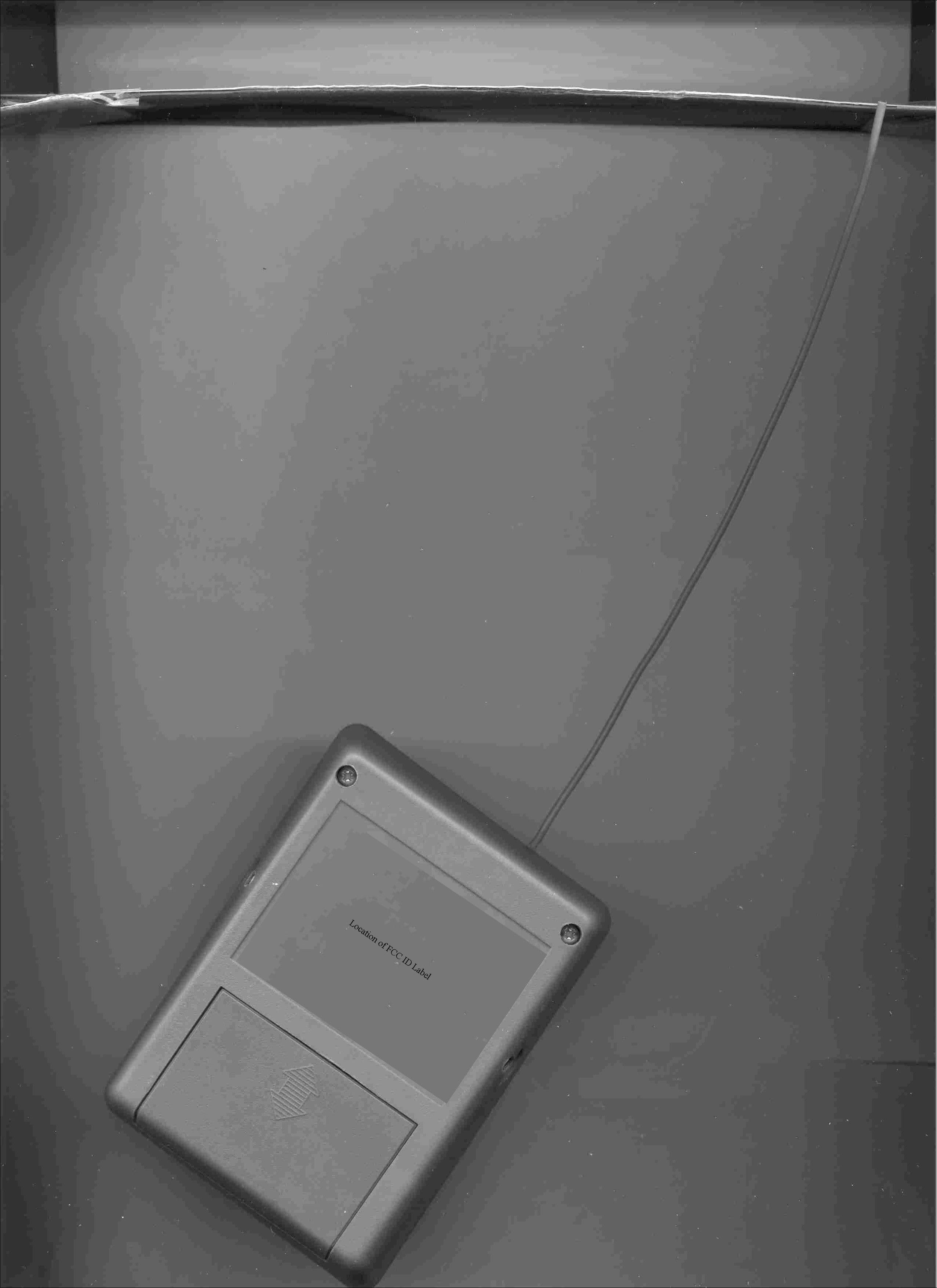
Click to zoom
Application Details
- Equipment Class
- DSC - Part 15 Security/Remote Control Transmitter
- Date of Grant
- Jun 25, 2000
- Application Purpose
- Original Equipment
- Date of Application
- Apr 24, 2000
- Equipment Note
- Motion Detector Transmitter
- Frequency Range
- 303.80000000 - 303.80000000
- Country
- United States
Documents & Files
Document Text
Text extracted from the exhibit documents filed with the FCC. Open a document above to read the original.
Users Manual
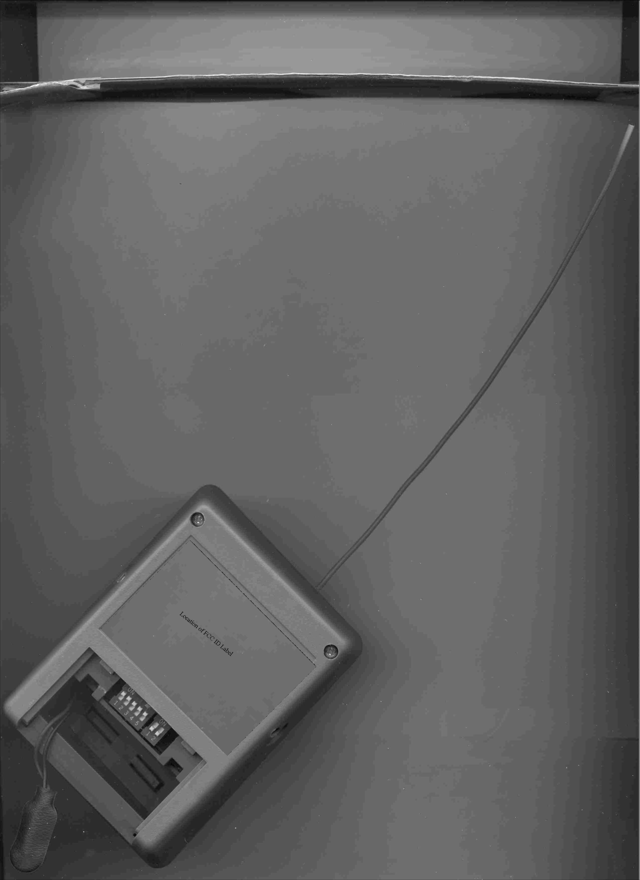
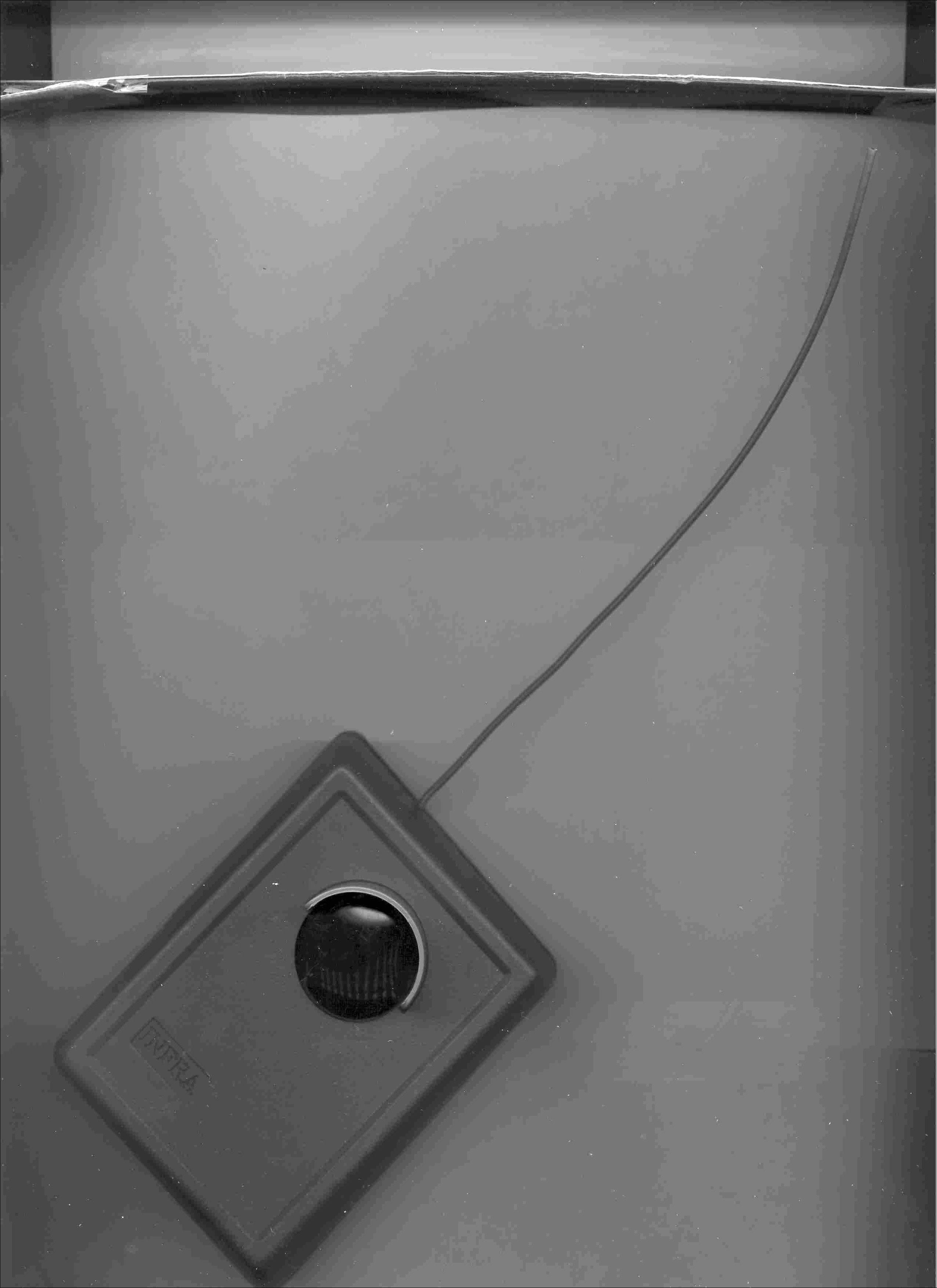
Alert System Model 1000 Receiver and Sensor/Transmitter INSTRUCTION MANUAL MILTRONICS Manufacturing, Inc. 95 Krif Road Keene, NH 03431 1-603-352-3333 Read entire manual prior to installation and operation. CAUTION: Changes or modifications not expressly approved by Miltronics could void the user’s authority to operate this device. This device complies with part 15 of the FCC Rules. Operation is subject to the following two conditions: (1) This device may not cause harmful interference, and (2) This device must accept any interference received, including interference that may cause undesired operation. This equipment has been tested and found to comply with the limits for an intentional radiator pursuant to Part 15 of the FCC Rules. These limits are designed to provide reasonable protection against harmful interference in a residential installation. This equipment generates, uses, and can radiate radio frequency energy and if not installed and used in accordance with the instructions may cause harmful interference to radio communications. However, there is no guarantee that interference will not occur in a particular installation. If this equipment does cause interference to radio or television reception, which can be determined by turning the equipment off and on, the user is encouraged to try to correct the interference by one or more of the follow ing meas ures: • Reorient or relocate the receiving antenna • Increase the separation between the equipment and receiver • Connect the equipment into an outlet on a circuit different from that to which the receiver is connected • Consult the dealer or an experienced radio/TV technician for help As an option, additional receivers and sensors may be used in conjunction with your driveway system. This will allow you to place them in various locations for your convenience. INFRA RED SENSOR/TRANSMITTER OPERATION: The infrared detector is positioned behind the round lens. It has a horizontal detection angle of 40 degrees. The effective detection range of the sensor is from 0 feet to 40 feet. The infrared sensor detects vehicles, intruders, guests etc., by sensing their heat and motion. When someone or something moves through the detection zone, the sensor detects the intrusion and transmits a signal to the receiver. INFRA RED SENSOR/TRANSMITTER INSTALLATION: First, install a high quality, 9-volt, alkaline battery in the compartment located in back of the sensor. Securely close the batter y cover. Mount the sensor approximately 2-3 feet above the ground to a tree, wooden post or side of a building. A metal bracket is provided. The lens must have an unobstructed view of the coverage area. Extend the flexible wire antenna upward. Some objects may not be detected if the sensor is placed too high or too low. Adjusting may be required prior to calling for technical support. Keep the sensor as close to the edge of the driveway as possible. The sensor should be strategically located so that it detects objects moving across detection zone. Do not mount the sensor facing the sun, bodies of water or any reflections. This causes variations in the temperature pattern “seen” by the sensor and may cause false alarms or damage the lens. PLEASE NOTE: A shorter transmission range may occur when the outside temperature falls below 20 degrees F. due to a natural drop in battery voltage. Lower sensitivity may occur during periods of fog, rain or snow. This is due to the moisture diffusing the infrared energy. The sensor/transmitters are rated to -40 degrees F. RECEIVER OPERATION: Plug the transformer into a 110-volt, indoor outlet. Stand receiver up or mount to wall and extend the flexible antenna upward (or attach rubberized antenna). The receiver will sound the alert when the sensor is activated. The alert sound re-sets itself on the 5th second and will continue to alert you with every intrusion. The light emitting diode will light when the receiver is activated and will remain lit until the button is manually reset. In unobstructed space, the reception range can reach up to 1000 feet. Range may be reduced by certain obstructions. For instance; metal buildings, dense woods, etc. For maximum range, locate the receiver in an area in your home with some direct visibility to the sensor. WALK TEST: After setting up your system perform a “walk” test to ensure the operation. Walk and drive through the detection area and have someone listen for the receiver to sound. The sensor then can be re-positioned if not properly performing. CODING ADJUSTMENT: The system coding is factory pre-set and should be adjusted only in the event of interference from another source. A DIPswitch is located in each the sensor and receiver. Only the first five positions on the switches can be changed and the switch settings in the transmitter must match the settings in the receiver. TROUBLESHOOTING: As with all passive infrared devices certain weather conditions and other acts of nature may cause false alarms or reduce sensitivity. Below is a list of the most common problems and the solutions to solve them. PROBLEMS can be caused by: Use of a low quality or non-alkaline battery. Use of an old, weak battery. The sun shining into the sensor lens. The sun reflecting off shiny objects. An improperly mounted or poorly secured sensor. SOLUTIONS: Replace battery with a new, high grade alkaline. Position the sensor so it has a clear view. Re-position sensor away from direct sun rays. Mount and secure sensor properly. Re ad a nd follo w t he “Inf ra Re d Se nsor/ T ra ns mitte r Instal latio n” a nd “ Re ce ive r O pe ration” se ctions, co rre ct pro ble m and perform “Walk Test” to verify operation. LIMITED WARRANTY Miltronics Manufacturing, Inc. will guarantee this product to be free from manufacturing defects for ten years from date of purchase. This warranty shall not apply to defects resulting from improper installation or use, unauthorized repair and consequent damage, abuse, modification, using in a …
Text truncated - open the document above for the full version.
ID Label/Location Info
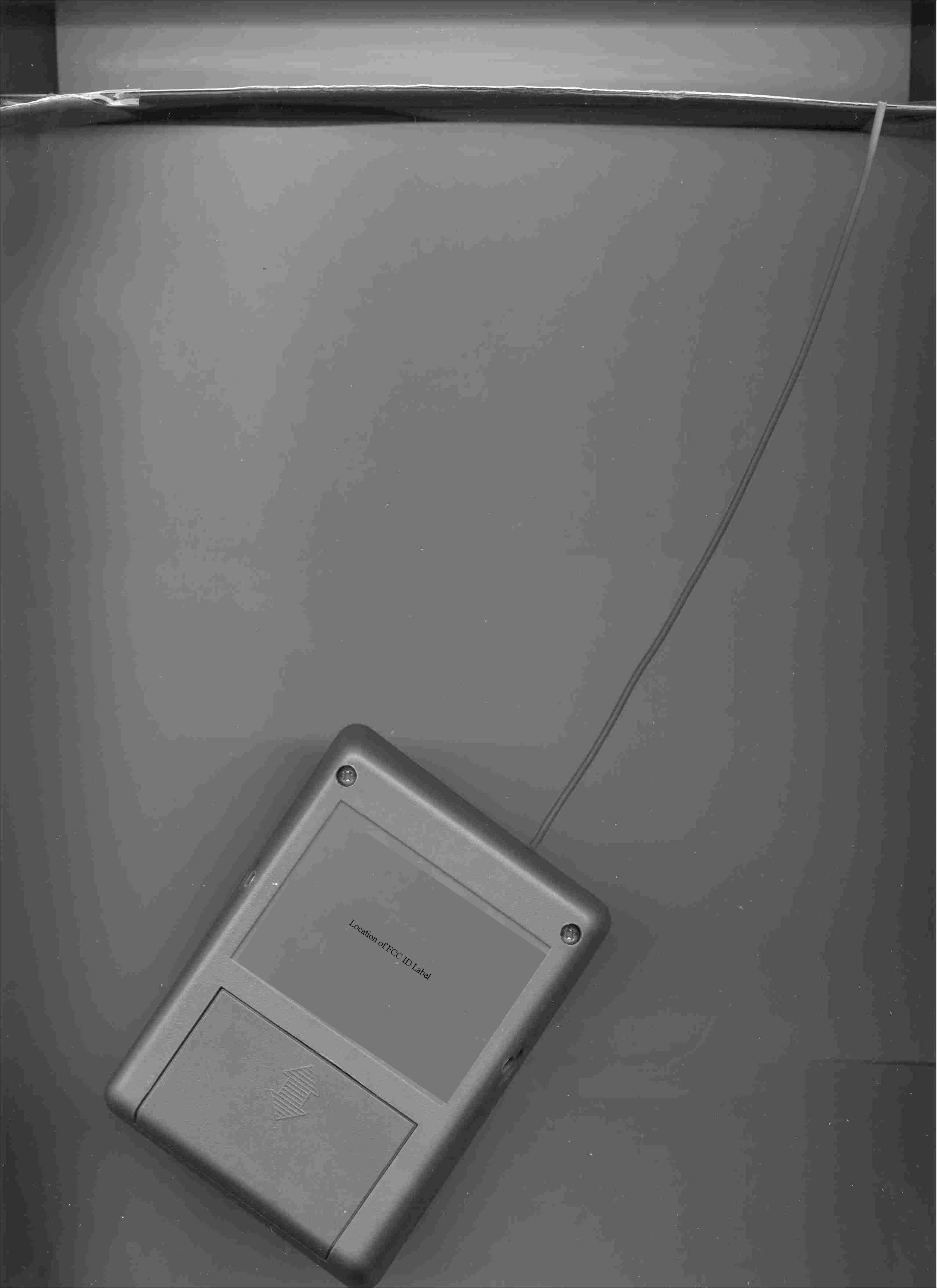
Label Location: Rear of Transmitter, above battery compartment FCC ID: OZDMLTRNXSENSXMIT Miltronics Sensor/Trans mi tter This device complies with part 15 of the FCC Rules. Operatio n is s ubje ct to the fo llo wing two co nd itio ns : (1) this device may not cause harmful interference and (2) this device must accept any interference received, including interference that may cause undesired operation.
Operational Description
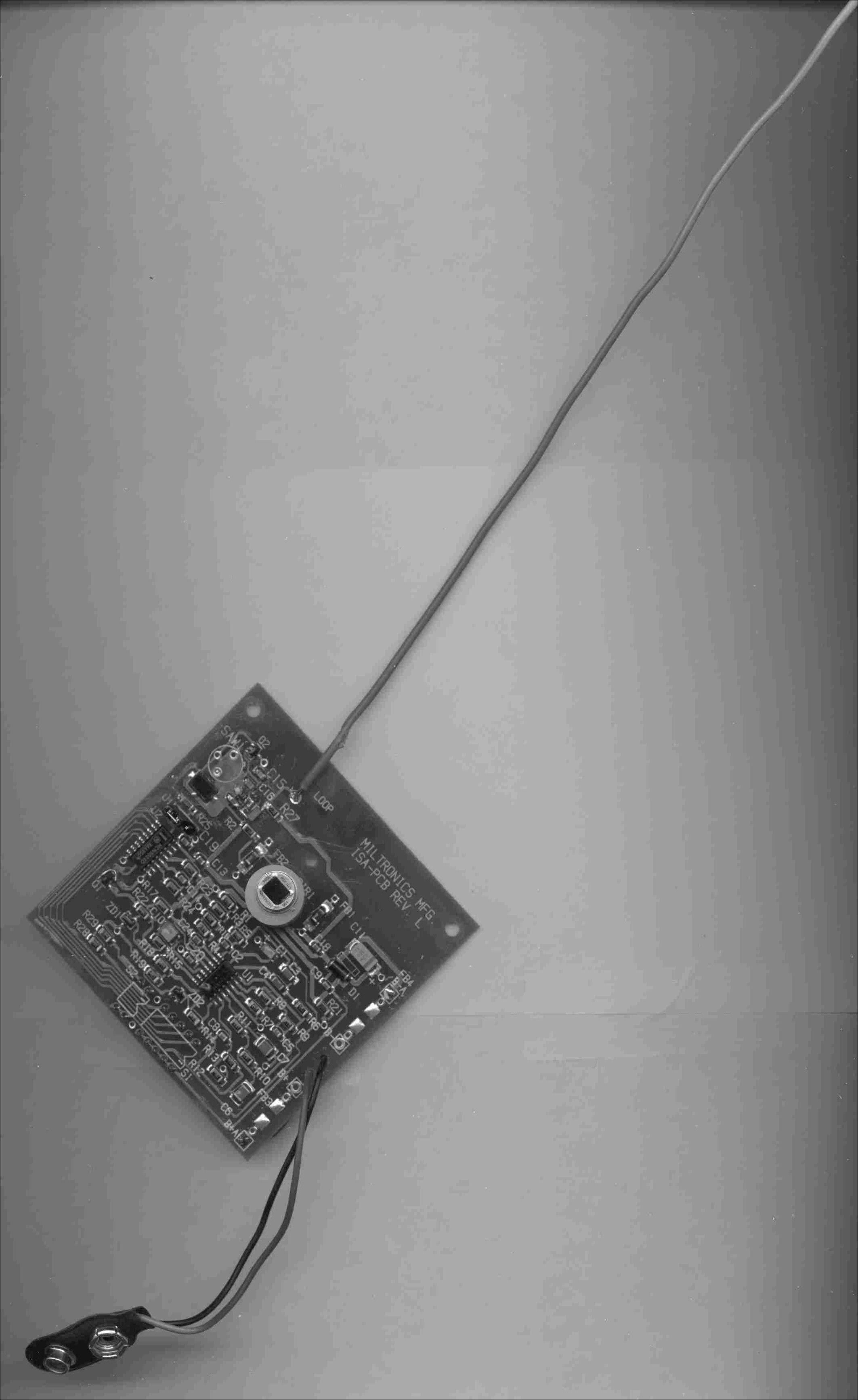
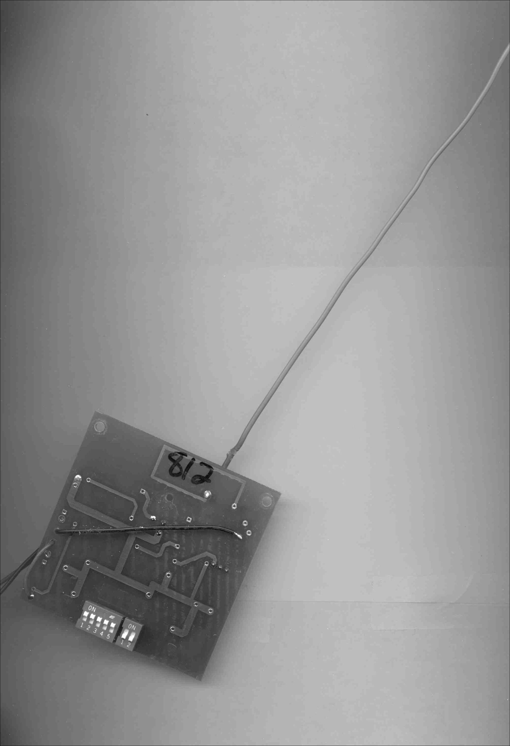
Description of circuitry in Miltronics Detection System Transmitter. January 28, 2000 / eef As a reference to the following description refer to the Block Diagram – Transmitter sheet and the Sensor Transmitter schematic. The Pyroelectric Infra Red (PIR) sensor along with the input lens form the sensing device used in the Miltronics motion sensing and notification systems. The PIR produces an output which varies with changes in radiation (temperature) levels, the change may can be caused by a person, animal, automobile or other object which has a radiation (temperature) level different from the background level. When the object passes in front of the PIR (denoted as PIR1 on the schematic) sensor a change in the output will be produced. The PIR output is amplified, filtered and compared with the 4 sections of operational amplified U1. The output from U1 pin 7 will change states in response to a change in radiation at the PIR input indicating the presence of an object. The output of U1 will remain active for a few seconds and then return to an inactive state until another object passed in front of the PIR sensor. The signal is then inverted by Q1 and applied to the enable pin of the encoding integrated circuit, a MC145026 (U2). When enabled (pin 14 low) the encoder IC will produce a coded pulse sequence at the output pin 15. The code sequence is determined by the settings of the 5 position DIP switch, S1. The output from the encoder is applied to a Surface Acoustic Wave (SAW) resonator. When the encoder output is high the resonator will produce an oscillation at 303.825 Mhz, when the output is low the oscillation will stop. Thus when enabled the encoder will produce a sequence of oscillations, non-oscillations at the SAW. The transistor, Q2, will amplify the oscillations from the SAW and apply an encoded power amplified signal to the antenna. The antenna will radiate RF energy in a modulated (determined by the encoding IC) burst mode each time an object is passed in the field of the PIR. The antenna consist of a loop etched into the PCB and an 8 inch length of insulated wire. A receiver tuned to the same 303 Mhz frequency in conjunction with a decoder integrated circuit will be used to detect and notify (by turning on a light or audio alarm) from a remote location, that an object has passed in front of the PIR sensor.
Test Report
Miltronics Manufacturing, Inc. 95 Krif Road Keene, NH 03431 March 28, 2000 Federal Communicatio ns Co mmission Equipment Authorization Division Applications Processing Branch 7435 Oakland Mills Road Columbia, MD 21046 Ref: Request for Confidentiality Dear Sir/Madam, We at Miltronics Manufacturing, Inc. request that the schematic diagrams, parts lists and system block diagrams submitted with this certification application be withheld from public disclosure as per Section 0.459 of the FCC Rules. This request is made under the provisions of Section 0.457(d) of the commissions rules and Section 0.552(b)(4) of the Freedom of Information Act. Disclosure of this design would place Miltronics Manufacturing, Inc. at a competitive disadvantage. Respectfully Submitted, Stephen T. Neary
Test Report
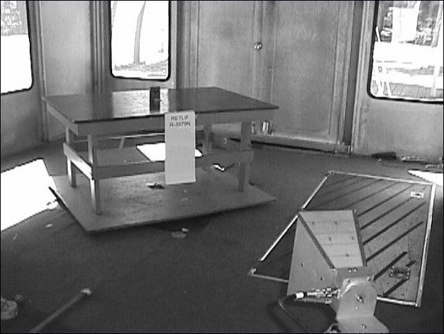
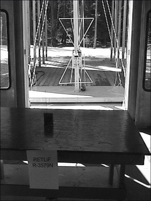
RETLIF TESTING LABORATORIES TABULAR DATA SHEET TEST METHOD : Radiated Emissions 30 MHz to 3.1 GHz CUSTOMER : Miltronics Manufacturing Services, Inc JOB NO : R-3579N TEST SAMPLE : Sensor/Transmitter for the Alert System Model 1000 MODEL NO : 1000 SERIAL NO : n/a TEST SPECIFICATION : FCC Part 15, Subpart C, Paragraph 15.201 General, 15.231 Specific OPERATING MODE : Continuously Transmitting TECHNICIAN : T. Firkowski DATE : 3/27/00 NOTES : Detector Function: Peak with Duty Cycle Test Distance: 3 Meters TEST FREQUENCY ANTENNA POSITION METER READING CORRECTION FACTOR DUTY CYCLE FACTOR CORRECTED READING CONVERTED READING LIM IT @ 3 M ETERS M Hz(H/V)dBuVdBdBdBuV/muV/muV/m 303.8V57.418.6-6.569.529855575 607.6V40.37.7-6.541.5119558 911.4V44.014.5-6.552.0398558 1215.1V68.8-13.7-6.548.6269500 1519.1V53.9-11.1-6.536.365500 1822.8V49.3-9.0-6.533.849558 2126.6V56.0-9.0-6.540.5106558 2430.4H53.3-7.7-6.539.190558 2734.2V47.4-4.9-6.53663500 3038.0V45.6-4.9-6.534.251558 EUT emissions observed throughout the given frequency spectrum w ere recorded and evaluated. Emission levels closest to the limit are listed on this data sheet. DATA SHEET 1 of 1 R- 3579N
Test Report
April 25, 2000 Federal Communications Commission Equipment Approval Services PO Box 358315 Pittsburgh, PA 15251-5315 Dear Sir/Madam: Enclosed you will find an application for Certification of a Sensor/Transmitter for the Alert System Model 1000, FCC ID: OZDMLTRNXSENSXMIT. Certification is requested to the requirements of Part 15, Subpart C of the Commission’s rules. This application is being filed by Retlif Testing Laboratories on behalf of Miltronics Manufacturing Services, Inc. The applicable Certification Filing Fee and 731 Form have been submitted. I trust that you will find the enclosed application to be complete; however, should you have any questions or require any additional information, please feel free to contact us. Very truly yours, RETLIF TESTING LABORATORIES Scott Wentworth Manager Enc. (as stated) Test Report No. R-3579N FCC ID: OZDMLTRNXSENSXMIT APPLICANT Miltronics Manufacturing Services, Inc. 95 Krif Road Keene NH 03431 MANUFACTURER SAME Test Report No. R-3579N FCC ID: OZDMLTRNXSENSXMIT Test Report No. R-3579N FCC ID: OZDMLTRNXSENSXMIT TEST SPECIFICATION: FCC Rules and Regulations Part 15, Subpart C, Para. 15.231 Test Report No. R-3579N FCC ID: OZDMLTRNXSENSXMIT TEST PROCEDURE: ANSI C63.4:1992 Test Report No. R-3579N FCC ID: OZDMLTRNXSENSXMIT Test Report No. R-3579N FCC ID: OZDMLTRNXSENSXMIT Test Report No. R-3579N FCC ID: OZDMLTRNXSENSXMIT TEST SAMP LE DESCRIP TION Test Report No. R-3579N FCC ID: OZDMLTRNXSENSXMIT BRANDNAME: Miltronics Manufacturing Services, Inc. MODEL: Alert System Model 1000 Test Report No. R-3579N FCC ID: OZDMLTRNXSENSXMIT TYPE: Sensor/Transmitter for the Alert System Model 1000 Test Report No. R-3579N FCC ID: OZDMLTRNXSENSXMIT Test Report No. R-3579N FCC ID: OZDMLTRNXSENSXMIT POWER REQUIREMENTS: 9Volt DC Battery Test Report No. R-3579N FCC ID: OZDMLTRNXSENSXMIT FREQUENCY OF OPERATION: 303.8MHz Test Report No. R-3579N FCC ID: OZDMLTRNXSENSXMIT FCC ID: OZDMLTRNXSENSXMIT Test Report No. R-3579N FCC ID: OZDMLTRNXSENSXMIT Test Report No. R-3579N FCC ID: OZDMLTRNXSENSXMIT APPLICABLE RULE SECTION: Part 15, Subpart C, Section 15.201 General Requirements and Test Report No. R-3579N FCC ID: OZDMLTRNXSENSXMIT 15.231 Alternative Requirements Test Report No. R-3579N FCC ID: OZDMLTRNXSENSXMIT Test Report No. R-3579N FCC ID: OZDMLTRNXSENSXMIT TESTS P ERFORMED Test Report No. R-3579N FCC ID: OZDMLTRNXSENSXMIT Radiated Emissions, Scan to 10 th Harmonic Test Report No. R-3579N FCC ID: OZDMLTRNXSENSXMIT Occupied Bandwidth, 0.25% of Fundamental Frequency Test Report No. R-3579N FCC ID: OZDMLTRNXSENSXMIT Duty Cycle Determination Test Report No. R-3579N FCC ID: OZDMLTRNXSENSXMIT Test Report No. R-3579N FCC ID: OZDMLTRNXSENSXMIT TEST SAMPLE OPERATION Test Report No. R-3579N FCC ID: OZDMLTRNXSENSXMIT The EUT is battery operated and was tested with newly installed batteries. For testing purposes only, Test Report No. R-3579N FCC ID: OZDMLTRNXSENSXMIT the EUT was configured to operate continuously, which required peak detector readings combined Test Report No. R-3579N FCC ID: OZDMLTRNXSENSXMIT with the duty cycle factor to produce the required average reading. Normal operation of the EUT Test Report No. R-3579N FCC ID: OZDMLTRNXSENSXMIT complies with the parameters required in Part 15, Subpart C, Section 15.231. Test Report No. R-3579N FCC ID: OZDMLTRNXSENSXMIT Test Report No. R-3579N FCC ID: OZDMLTRNXSENSXMIT TEST SAMP LE / TEST P ROGRAM Test Report No. R-3579N FCC ID: OZDMLTRNXSENSXMIT Test Report No. R-3579N FCC ID: OZDMLTRNXSENSXMIT • The transmitter is automatically activated and ceases transmission less than 5 seconds after Test Report No. R-3579N FCC ID: OZDMLTRNXSENSXMIT deactivation. Test Report No. R-3579N FCC ID: OZDMLTRNXSENSXMIT Test Report No. R-3579N FCC ID: OZDMLTRNXSENSXMIT • The transmitter does not perform periodic transmissions at regularly predetermined intervals. Test Report No. R-3579N FCC ID: OZDMLTRNXSENSXMIT Test Report No. R-3579N FCC ID: OZDMLTRNXSENSXMIT • The device can be employed for RC purposes involving security. Test Report No. R-3579N FCC ID: OZDMLTRNXSENSXMIT Test Report No. R-3579N FCC ID: OZDMLTRNXSENSXMIT • The fundamental field strength at 303.8MHz did not exceed 5575.0μV/M (Average) at a test Test Report No. R-3579N FCC ID: OZDMLTRNXSENSXMIT distance of 3 meters. In addition, the requirements of section 15.35 for averaging pulsed Test Report No. R-3579N FCC ID: OZDMLTRNXSENSXMIT emissions and for limiting peak emissions were met. Test Report No. R-3579N FCC ID: OZDMLTRNXSENSXMIT Test Report No. R-3579N FCC ID: OZDMLTRNXSENSXMIT • The field strength of harmonic and spurious emissions did not exceed 558μV/M or 500μV/M Test Report No. R-3579N FCC ID: OZDMLTRNXSENSXMIT as applicable. Test Report No. R-3579N FCC ID: OZDMLTRNXSENSXMIT Test Report No. R-3579N FCC ID: OZDMLTRNXSENSXMIT • The device operates at a frequency range of 303.8MHz. The bandwidth of emissions did not Test Report No. R-3579N FCC ID: OZDMLTRNXSENSXMIT exceed 0.25% of the operating frequency and was determined as follows: Test Report No. R-3579N FCC ID: OZDMLTRNXSENSXMIT Test Report No. R-3579N FCC ID: OZDMLTRNXSENSXMIT Fundamental Frequency=303.8MHz Test Report No. R-3579N FCC ID: OZDMLTRNXSENSXMIT 0.25% of Center Frequency =0.7595MHz
Test Report
Miltronics Manufacturing, Inc. 95 Krif Road Keene, NH 03431 March 28, 2000 Federal Communicatio ns Co mmission Equipment Authorization Division Applications Processing Branch 7435 Oakland Mills Road Columbia, MD 21046 Ref: Request for Confidentiality Dear Sir/Madam, We at Miltronics Manufacturing, Inc. request that the schematic diagrams, parts lists and system block diagrams submitted with this certification application be withheld from public disclosure as per Section 0.459 of the FCC Rules. This request is made under the provisions of Section 0.457(d) of the commissions rules and Section 0.552(b)(4) of the Freedom of Information Act. Disclosure of this design would place Miltronics Manufacturing, Inc. at a competitive disadvantage. Respectfully Submitted, Stephen T. Neary
Test Report
May 31, 2000 Federal Communications Commission Equipment Approval Services PO Box 358315 Pittsburgh, PA 15251-5315 Dear Sir/Madam: Enclosed you will find an application for Certification of a Sensor/Transmitter for the Alert System Model 1000, FCC ID: OZDMLTRNXSENSXMIT. Certification is requested to the requirements of Part 15, Subpart C of the Commission’s rules. This application is being filed by Retlif Testing Laboratories on behalf of Miltronics Manufacturing Services, Inc. The applicable Certification Filing Fee and 731 Form have been submitted. I trust that you will find the enclosed application to be complete; however, should you have any questions or require any additional information, please feel free to contact us. Very truly yours, RETLIF TESTING LABORATORIES Scott Wentworth Manager Enc. (as stated) Test Report No. R-3579N FCC ID: OZDMLTRNXSENSXMIT APPLICANT Miltronics Manufacturing Services, Inc. 95 Krif Road Keene, NH 03431 MANUFACTURER SAME TEST SPECIFICATION: FCC Rules and Regulations Part 15, Subpart C, Para. 15.231 TEST PROCEDURE: ANSI C63.4:1992 TEST SAMP LE DESCRIP TION BRANDNAME: Miltronics Manufacturing Services, Inc. MODEL: Alert System Model 1000 TYPE: Sensor/Transmitter for the Alert System Model 1000 POWER REQUIREMENTS: 9Volt DC Battery FREQUENCY OF OPERATION: 303.8MHz FCC ID: OZDMLTRNXSENSXMIT APPLICABLE RULE SECTION: Part 15, Subpart C, Section 15.201 General Requirements and 15.231 Alternative Requirements TESTS P ERFORMED Radiated Emissions, Scan to 10 th Harmonic Occupied Bandwidth, 0.25% of Fundamental Frequency Duty Cycle Determination TEST SAMPLE OPERATION The EUT is battery operated and was tested with newly installed batteries. For testing purposes only, the EUT was configured to operate continuously, which required peak detector readings combined with the duty cycle factor to produce the required average reading. Normal operation of the EUT complies with the parameters required in Part 15, Subpart C, Section 15.231. Test Report No. R-3579N FCC ID: OZDMLTRNXSENSXMIT TEST SAMP LE / TEST P ROGRAM • The transmitter is automatically activated and ceases transmission less than 5 seconds after deactivation. • The transmitter does not perform periodic transmissions at regularly predetermined intervals. • The device can be employed for RC purposes involving security. • The fundamental field strength at 303.8MHz did not exceed 5575.0μV/M (Average) at a test distance of 3 meters. In addition, the requirements of section 15.35 for averaging pulsed emissions and for limiting peak emissions were met. • The field strength of harmonic and spurious emissions did not exceed 558μV/M or 500μV/M as applicable. • The device operates at a frequency range of 303.8MHz. The bandwidth of emissions did not exceed 0.25% of the operating frequency and was determined as follows: Fundamental Frequency=303.8MHz 0.25% of Center Frequency =0.7595MHz 0.7595 divided by 2=0.379MHz Bandwidth Range=Fundamental Frequency + and - 0.379MHz 303.8MHz - 0.379MHz=303.421MHz 303.8MHz + 0.379MHz=304.179MHz Bandwidth Range=303.421MHz - 304.179MHz • The device uses a permanently attached 7_" straight wire antenna. • Radiated Emissions from the EUT were measured in all three axis. Worst case emissions were found with the EUT in the vertical upright position, with the antenna pointed straight up. This orientation is also the position in which the device will normally be installed. The attached Radiated Emissions test data is representative of this worst case orientation. Test Report No. R-3579N FCC ID: OZDMLTRNXSENSXMIT TEST SAMPLE / TEST PROGRAM (continued) DETERMINATION OF FIELD STRENGTH LIMITS The field strength limits shown below were calculated as instructed in Section 15.231. Fundamental Frequency: 303.8MHz Where F is the frequency in MHz, the formula for calculating the maximum permitted fundamental field strength for the band 260-470MHz, μV/m at 3 meters is as follows: 41.6667(F) - 7083.3333 =Field Strength Limit (μV/m) 41.6667 x 303.8=12658.343 12658.343 - 7083.3333=5575 Field Strength Limit=5575 μV/m The maximum permitted unwanted emission level is 20dB below the maximum permitted fundamental level. DETERMINATION OF DUTY CYCLE The transmitter controls were adjusted to maximize the transmitted duty cycle. The analyzer was set for a frequency span of 0Hz. The sweep time was then adjusted in order to display one full pulse train. The transmitter on time was then summed and compared to the time for one full cycle in order to obtain the duty cycle. Transmitter On Time=22.5 milliseconds (maximum) Transmitter Cycle Time=47.75 milliseconds Transmitter Duty Cycle=47.1 % On Time divided by Cycle Time=Duty Cycle Factor 22.5 divided by 47.75=0.471 0.471 converted to dB (LOG 10 .471)20=-6.5dB Duty Cycle Factor=-6.5dB Duty Cycle Factor Determination Plots are included with this application as a separate attachment. Test Report No. R-3579N FCC ID: OZDMLTRNXSENSXMIT TEST SAMPLE / TEST PROGRAM (continued) SPECTRUM ANALYZER DESENSITIZATION CONSIDERATIONS Due to the nature of the emissions being measured, care was taken to ensure that the resolution bandwidth of the spectrum analyzer was adequate to provide accurate measurements. The following formula was utilized: Setting pulse desensitization equal to zero and utilizing the minimum observed pulse width of 1.4 milliseconds yields a minimum required bandwidth of 476 Hz. FCC specified bandwidths of 100kHz and 1MHz were utilized below and above 1GHz, respectively. GENERAL NOTES 1. All readings were taken utilizing a peak detector function at a test distance of 3 meters. 2. The duty cycle was applied to the peak readings in order to determine the average value of the emissions. 3. The frequency range was scanned from 30 MHz to 3.1 GHz. Emission levels closest to the specified limit are listed on the attached data sheet. Test Report No. R-3579N FCC ID: OZDMLTRNXSENSXMIT EQUIPMENT LISTS Spurious Radiated Emissions ENTypeManufacturer Frequency RangeModel No.Cal DateDue…
Text truncated - open the document above for the full version.
Contact Information
Applicant
Stephen T Neary(Vice President)
Technical Contact
Retlif Testing LaboratoriesJohn Monahan
[email protected]603-497-4600
101 New Boston Road · Goffstown, New Hampshire · United States
Non-Technical Contact
Retlif Testing LaboratoriesScott Wentworth
[email protected]603-497-4600
Technical Specifications
| # | Rule Parts | Frequency Range | Power Output | Tolerance |
|---|---|---|---|---|
| 1 | 15C | 303.8 MHz - 303.8 MHz | - | % |