OZR837-3510RF receiver
Computer Process Controls Inc.
Click to zoom
Application Details
- Equipment Class
- CYY - Communications Receiver used w/Pt 15 Transmitter
- Date of Grant
- Dec 10, 2000
- Application Purpose
- Original Equipment
- Date of Application
- Nov 19, 2000
- Equipment Note
- RF receiver
- Frequency Range
- 418.00000000 - 418.00000000
- Country
- United States
Documents & Files
Document Text
Text extracted from the exhibit documents filed with the FCC. Open a document above to read the original.
Users Manual
026-1702 Rev 0 10-30-00 Radio Frequency (RF) Temperature Sensor System Installation and Operation Manual 1640 Airport Road, Suite 104 Kennesaw, GA 31044 Phone: (770) 425-2724 Fax: (770) 425-9319 ALL RIGHTS RESERVED. The information contained in this manual has been carefully checked and is believed to be accurate. However, Com- puter Process Controls, Inc. assumes no responsibility for any inaccuracies that may be contained herein. In no event will Computer Process Controls, Inc. be liable for any direct, indirect, special, incidental, or consequential damages resulting from any defect or omission in this manual, even if advised of the possibility of such damages. In the interest of continued product development, Computer Process Controls, Inc. reserves the right to make improvements to this manual, and the products described herein, at any time without notice or obligation. FCC COMPLIANCE NOTICE NOTE: This equipment has been tested and found to comply with the limits for a Class B digital device, pursuant to Part 15 of the FCC Rules. These limits are designed to provide reasonable protection against harmful interference in a res- idential installation. This equipment generates, uses, and can radiate radio frequency energy and, if not installed and used in accordance with the instructions, may cause harmful interference to radio communications. However, there is no guar- antee that interference will not occur in a particular installation. If this equipment does cause harmful interference to radio or television reception, which can be determined by turning the equipment off and on, the user is encouraged to try and correct the interference by one or more of the following measures: -- Reorient or relocate the receiving antenna -- Increase the separation between the equipment and the receiver -- Connect the equipment into an outlet on a circuit different from that to which the receiver is connected -- Consult the dealer or an experienced radio/TV technician for help READ ALL INSTRUCTIONS CAREFULLY before attempting to install or operate the RF Sensor Sys- tem. SAVE THIS INSTRUCTION MANUAL — This instruction manual contains important operating instruc- tions for the RF Sensor System. Warning! FCC Regulations state that any unauthorized changes or modifications to this equipment not expressly ap- proved by the manufacturer could void the user's authoriza- tion to operate this equipment. Table of Contents • 1 Table of Contents 1 OVERVIEW ................................................................................................................................................................... 1 1.1. S YSTEM D ESCRIPTION .................................................................................................................................................. 1 1.2. H ARDWARE C OMPONENTS ........................................................................................................................................... 3 1.2.1. Sensors .................................................................................................................................................................. 3 1.2.1.1. RF Ambient Temperature Sensors...................................................................................................................................... 3 1.2.1.2. RF Long-Range Ambient Sensors ...................................................................................................................................... 4 1.2.1.3. RF Product Simulator ......................................................................................................................................................... 4 1.2.2. RF Receiver ........................................................................................................................................................... 5 1.2.3. RF Gateway........................................................................................................................................................... 5 1.2.4. Hand-Held Terminal ............................................................................................................................................. 6 2 INSTALLING THE RF GATEWAY........................................................................................................................... 7 2.1. M OUNTING THE RF G ATEWAY ..................................................................................................................................... 7 2.2. P OWERING THE RF G ATEWAY ..................................................................................................................................... 7 2.3. W IRING THE RF G ATEWAY TO A CPC S ITE C ONTROLLER (I/O N ETWORK )................................................................ 8 2.3.1. Wire Connection ................................................................................................................................................... 8 2.3.2. Setting the Board Numbering Dip Switch ............................................................................................................. 8 2.3.3. Setting the Baud Rate Dip Switch ......................................................................................................................... 9 2.3.4. Setting the RS485 I/O Termination Jumpers......................................................................................................... 9 2.4. N ETWORKING G ATEWAYS AND R ECEIVERS (T OKEN R ING N ETWORK ) ..................................................................... 10 2.4.1. Wiring the Token Ring Network to the Gateway................................................................................................. 10 2.4.2. Setting the Token Ring Network Termination Jumpers ...................................................................................... 10 3 INSTALLING THE RF RECEIVER..............................…
Text truncated - open the document above for the full version.
Operational Description
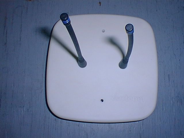
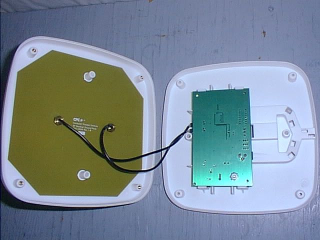
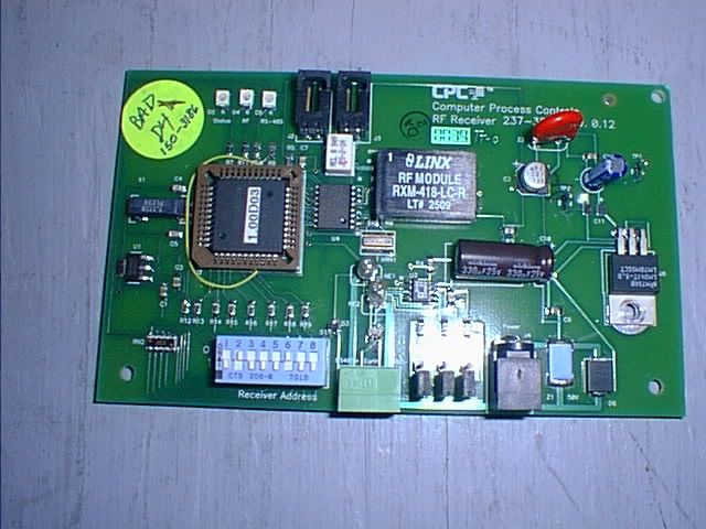
The CPC 837-3510 Receiver is composed of three basic functional blocks: the power supply, the RF section, and the output communication section. The power supply is formed using a 120VAC-to-9VDC Class II transformer. The PCB has a connector on-board to allow connection of the power supply, some protection components, and a National Instruments LM340 5V voltage regulator. The RF section is composed of two antennae, a 0-degree phase power splitter, and a Linx Technologies RXM-418-LC receiver. The communication section is formed with a Motorola MC68HC705KJ1CDW, which decodes the base-band information, a Motorola MC68HSC705C8ACFN microprocessor which controls the output, an RS-485 output driver, and three LED’s to supply visual status information. Incoming transmissions are routed from the two antennae to the Linx Technologies RXM-418-LC via the power splitter, where they are converted to a base-band serial data stream. This serial data stream is decoded by the Motorola MC68HC705KJ1CDW which supplies the data via a parallel connection to the Motorola MC68HSC705C8ACFN microprocessor. The microprocessor outputs the data to the RS-485 driver (U3 on the schematic). The data flow is only in this one direction.
Test Report
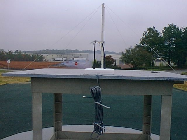
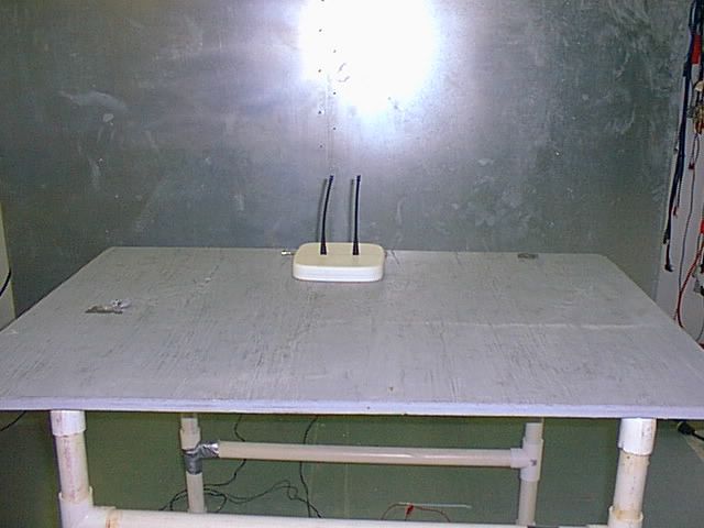
RF Emissions Test Report To Determine Compliance With: FCC, Part 15 Rules and Regulations Model number: 837-3510 October 23, 2000 Manufacturer: Computer Process Control 1640 Airport Road Suite 104 Kennesaw, GA 30144 EMC Testing Laboratories, Inc. authorizes the above company to reproduce this report provided it is reproduced in its entirety EMC Testing Lab. (770) 781-9228 Test report no. 00-199A Page 2 2 of 1 1 7 7 Contents Section General Information .......................................................................1 Test Summary..................................................................................2 Standard Reference ........................................................................3 Test Method ..........................................................................4 Radiated Emissions Measurements ................................................5 Conducted Emissions Measurements ..............................................6 Configuration ...........................................................................7 EMC Testing Lab. (770) 781-9228 Test report no. 00-199A Page 3 3 of 1 1 7 7 Section 1 General Information Manufacturer: Computer Process Control 1640 Airport Road Suite 104 Kennesaw, GA 30144 Manufacturer representative:Mr. Scott Gelber Equipment covered by this report: Model no. 837-3510 Options covered by this report: None Equipment serial no. Prototype Test specifications: To determine compliance with: FCC, Part 15, Subpart B Rules and Regulations, Class B Test report number: 00-199A Test commenced: October 20, 2000 Test completed: October 20, 2000 Test engineer:Kent Stewart Test Facility: The test facility used to perform these tests is on file with the FCC under file 31040/SIT, 1300F2 and located at: EMC Testing Laboratories, Inc. 2420 Oak Street West Cumming, GA. 30041-6456 EMC Testing Lab. (770) 781-9228 Test report no. 00-199A Page 4 4 of 1 1 7 7 Section 2 Test report summary sheet 1 of 3 Summary: TestsResults FCC, Part 15, Class B, Radiated emissions: Pass FCC, Part 15, Class B, Conducted emissions: Pass 1- The product(s) covered by this report was found to comply with the Class B radiated and conducted emission limits of the FCC, Part 15, Subpart B Rules and Regulations. 2- There were no measurable emissions within 20 dB μ v of the radiated or conducted limits with the antenna in the vertical or horizontal polarization. 3- The test results apply only to the products identified in this test report. Product description: The product(s) covered by this report consisted of a model 837-3510 receiver, which is intended for receiving temperature data at 418Mhz and outputs the data via RS-485 to a Gateway controller. The enclosure is constructed of plastic with overall dimensions measuring 3.7cm high by 20.1cm wide by 20.1cm deep and house’s the following components: 1- A wall adapter, manufactured by Airstack, model no. DV-9200, input rated 120Vac, 60Hz, 5W and output rated 9Vdc, 200mA. 2- A printed wiring board (antenna ground plane) manufactured by Computer Process Control, part number 237-3520 rev. 1. 3- A printed wiring board (main board) manufactured by Computer Process Control, part number 237537-3510 rev. 1. EMC Testing Lab. (770) 781-9228 Test report no. 00-199A Page 5 5 of 1 1 7 7 Test report summary sheet 2 of 3 Test configuration: The Equipment Under Test (EUT) was set-up and configured as specified by the manufacturer as follows: 1- The EUT was connected to the following support peripherals. A) None 2- The EUT utilized the following cables and were connected as indicated below: A) A shielded, unterminated 2-conductor cable was connected to the EUT’s RS-485 port. Test operation: For all measurements, the equipment under test was caused to function in a continuous mode of operation for maximum electrical activity as specified by the manufacturer. Specifically, the EUT was powered on and waiting to receive while simultaneously try to communicate out the RS-485 cable. Modifications: The following modifications were required to comply with the indicated limits: 1- None Engineering Statement: All measurement data, of this test report, was taken in accordance with the FCC, Part 15, Subpart B Rules and Regulations and ANSI C63.4-1992 by EMC Testing Laboratories, Inc., located in Cumming, Georgia. Although this data is taken under stringent laboratory conditions and to the best of our knowledge, represents accurate data, it must be recognized that emissions from or immunity to this type equipment may be greatly affected by the final installation of the equipment. Therefore, EMC Testing Laboratories, Inc., while supporting the accuracy of the data in this report, takes no responsibility for use of equipment based on these tests. The manufacturer of this equipment must take full responsibility for any field problems which may arise, and agrees that EMC Testing Laboratories, Inc., in performing its functions in accordance with its objectives and purposes, does not assume or undertake to discharge any responsibility of the manufacturer to any other party or parties. EMC Testing Lab. (770) 781-9228 Test report no. 00-199A Page 6 6 of 1 1 7 7 Section 2 cont... Test report summary sheet 3 of 3 Conclusion: With the above indicated modifications, the product(s) covered by this report has been tested and found to comply with the limits for a Class B device in accordance with the FCC, Part 15, Subpart B Rules and Regulations. Tested by:Reviewed by: Kent StewartGene J. Bailey Laboratory ManagerEngineering Manager EMC Testing Laboratories, Inc. October 23, 2000 EMC Testing Lab. (770) 781-9228 Test report no. 00-199A Page 7 7 of 1 1 7 7 Section 2 cont... This page intentionally left blank. (Reserved for future use) EMC Testing Lab. (770) 781-9228 Test report no. 00-199A Page 8 8 of 1 1 7 7 Section 3 STANDARD REFERENCE The following primary standards were used for this test: 1) ANSI C63.4-1992: Method of Measurements of Radio-Noise Emissions from Low- Voltag…
Text truncated - open the document above for the full version.
Contact Information
Applicant
Scott Gelber(Senior Engineer)
770-425-2724Fax: 770-419-7436
Technical Contact
EMC Testing Laboratories, Inc.Kent W Stewart
[email protected]770-781-9228
2420 Oak Street West · Cumming, Georgia · United States
Non-Technical Contact
EMC Testing Laboratories, Inc.Kent W Stewart
[email protected]770-781-9228
Test Firm
EMC Testing Laboratories, Inc.Gene Bailey
Technical Specifications
| # | Rule Parts | Frequency Range | Power Output |
|---|---|---|---|
| 1 | 15B | 418 MHz - 418 MHz | - |
Other Applications from Computer Process Controls Inc.

OZR809-3545
Feb 20, 2001Wireless temperature sensor model 809-3545
Equipment Class
DXX - Part 15 Low Power Communication Device Transmitter
OZR809-3543
Feb 19, 2001Wireless temperature sensor model 809-3543
Equipment Class
DXX - Part 15 Low Power Communication Device Transmitter
OZR809-3542
Dec 26, 2000RF ambient temperature sensor
Equipment Class
DXX - Part 15 Low Power Communication Device Transmitter
OZR809-3548
Dec 26, 2000RF product simulator
Equipment Class
DXX - Part 15 Low Power Communication Device Transmitter
OZR809-3544
Dec 26, 2000RF external ambient sensor
Equipment Class
DXX - Part 15 Low Power Communication Device Transmitter