OZTRCS16TXRadio Remote Control Transmitter RCS16TX
Irwin Technology Pty Ltd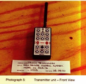
Click to zoom
Application Details
- Equipment Class
- DSC - Part 15 Security/Remote Control Transmitter
- Date of Grant
- Aug 30, 2000
- Application Purpose
- Original Equipment
- Date of Application
- May 11, 2000
- Equipment Note
- Radio Remote Control Transmitter RCS16TX
- Frequency Range
- 433.92000000 - 433.92000000
- Company
- Irwin Technology Pty Ltd
- Country
- Australia
Documents & Files
Document Text
Text extracted from the exhibit documents filed with the FCC. Open a document above to read the original.
Test Report
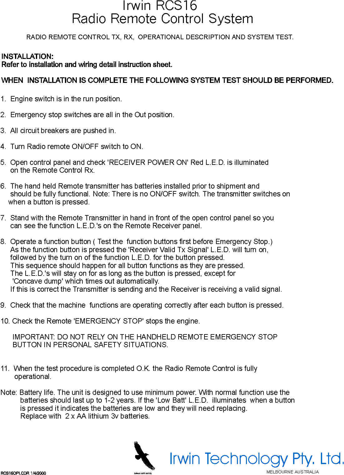
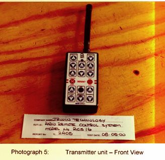
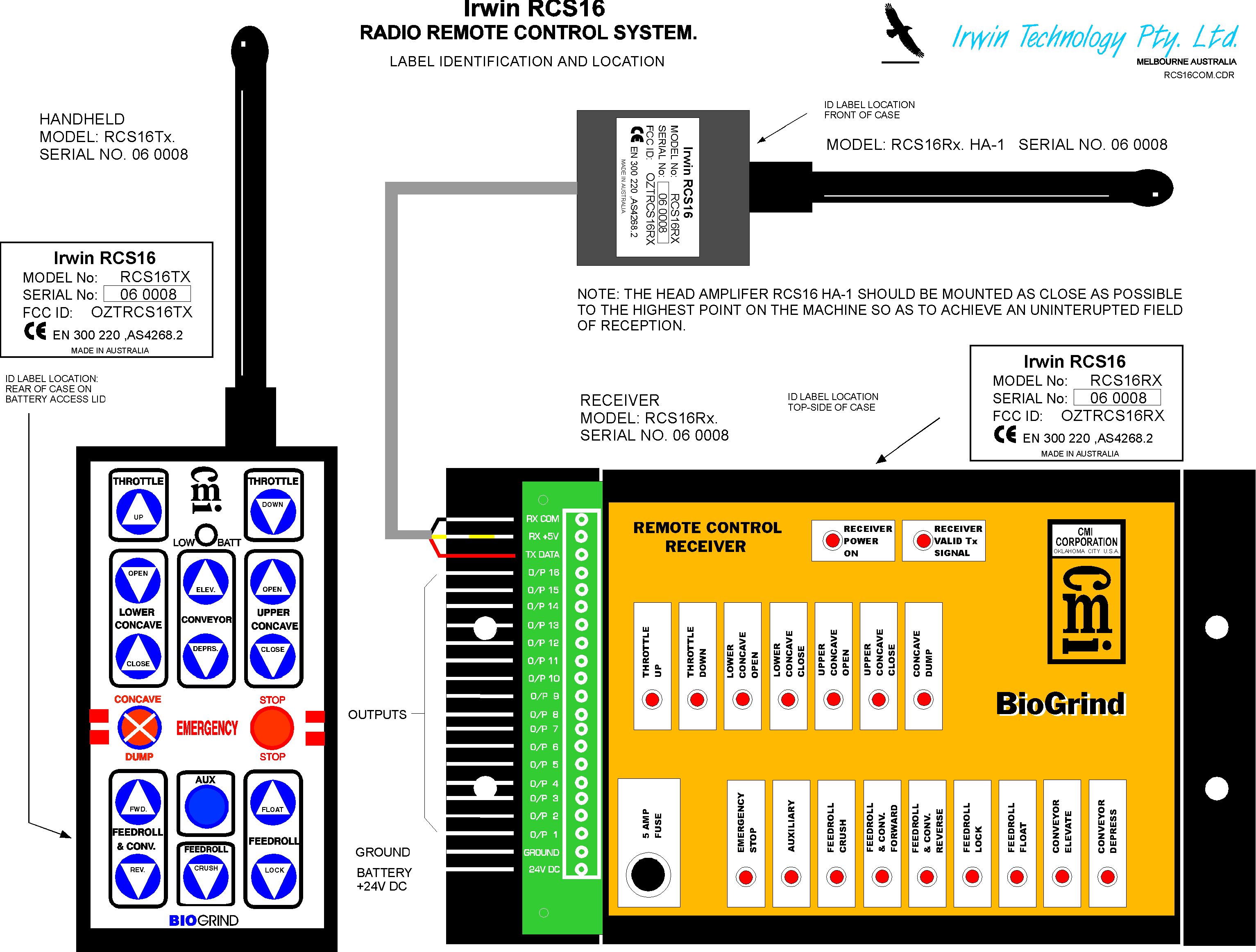
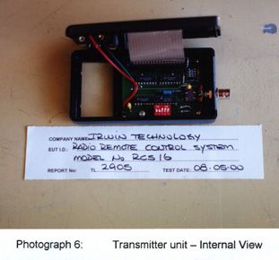
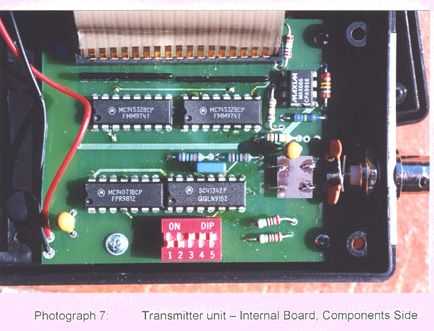
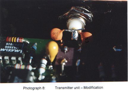
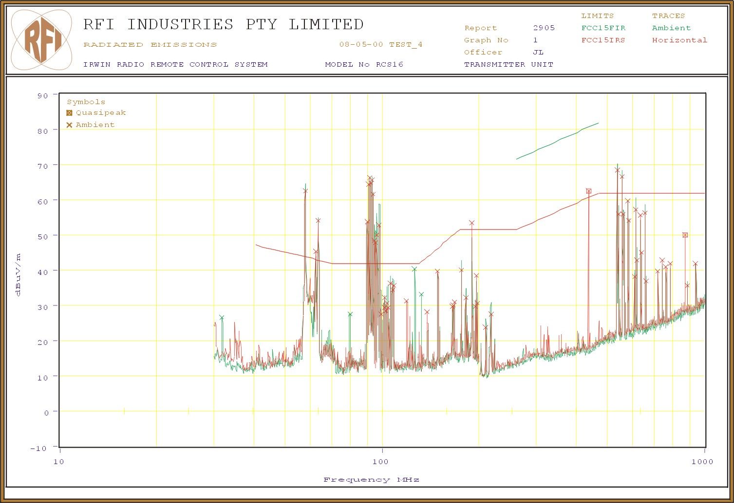
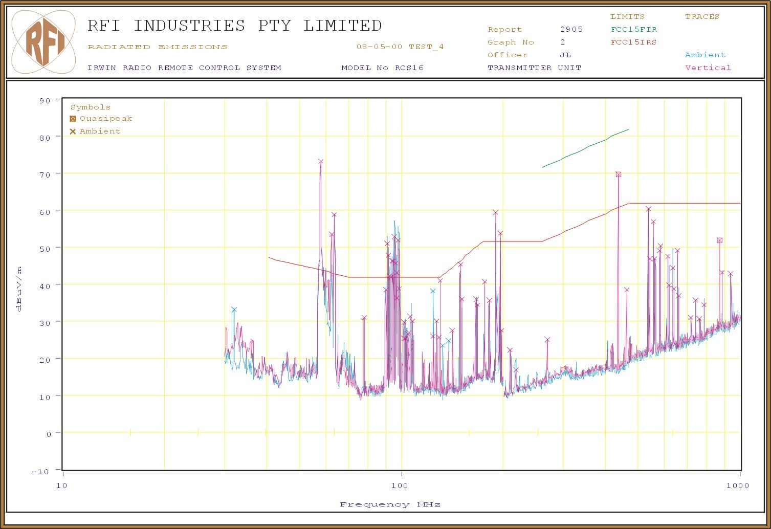
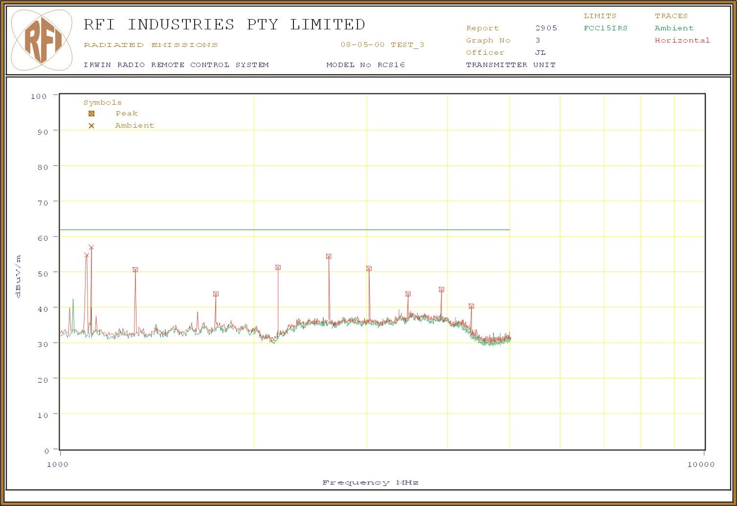
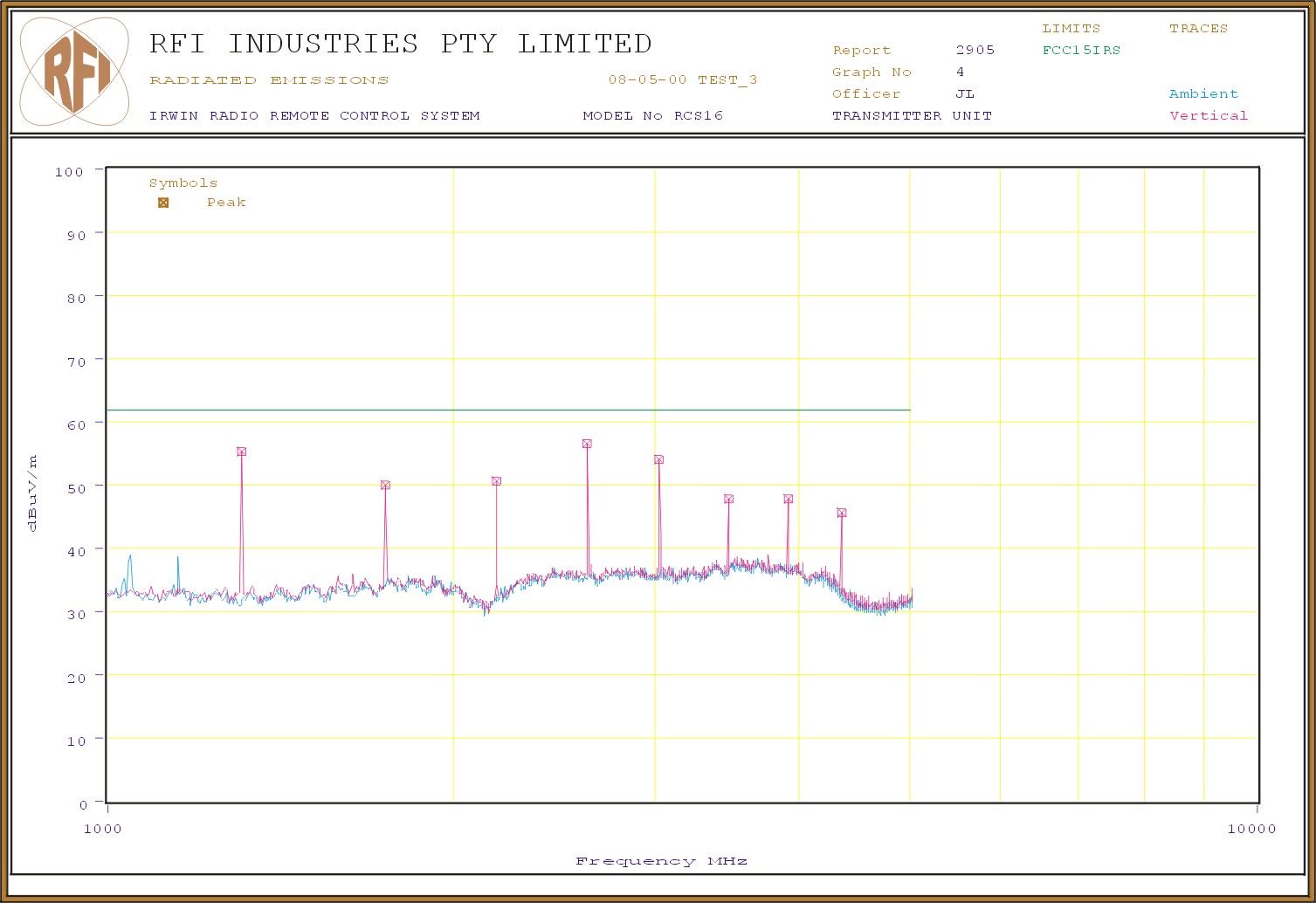
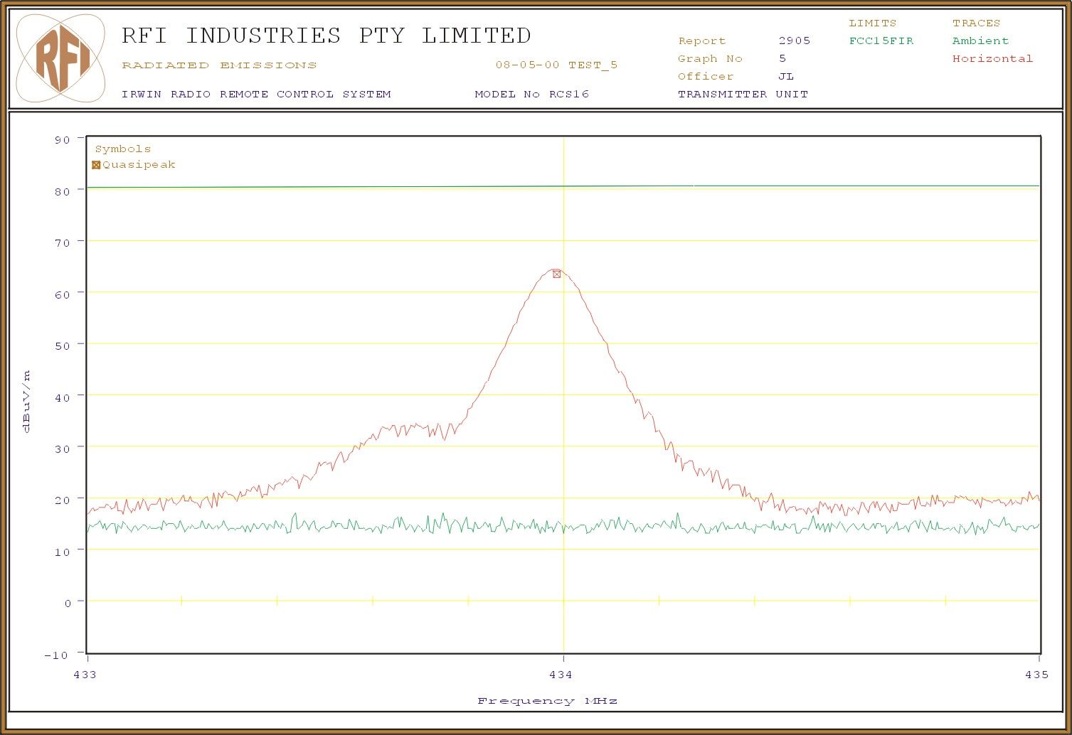
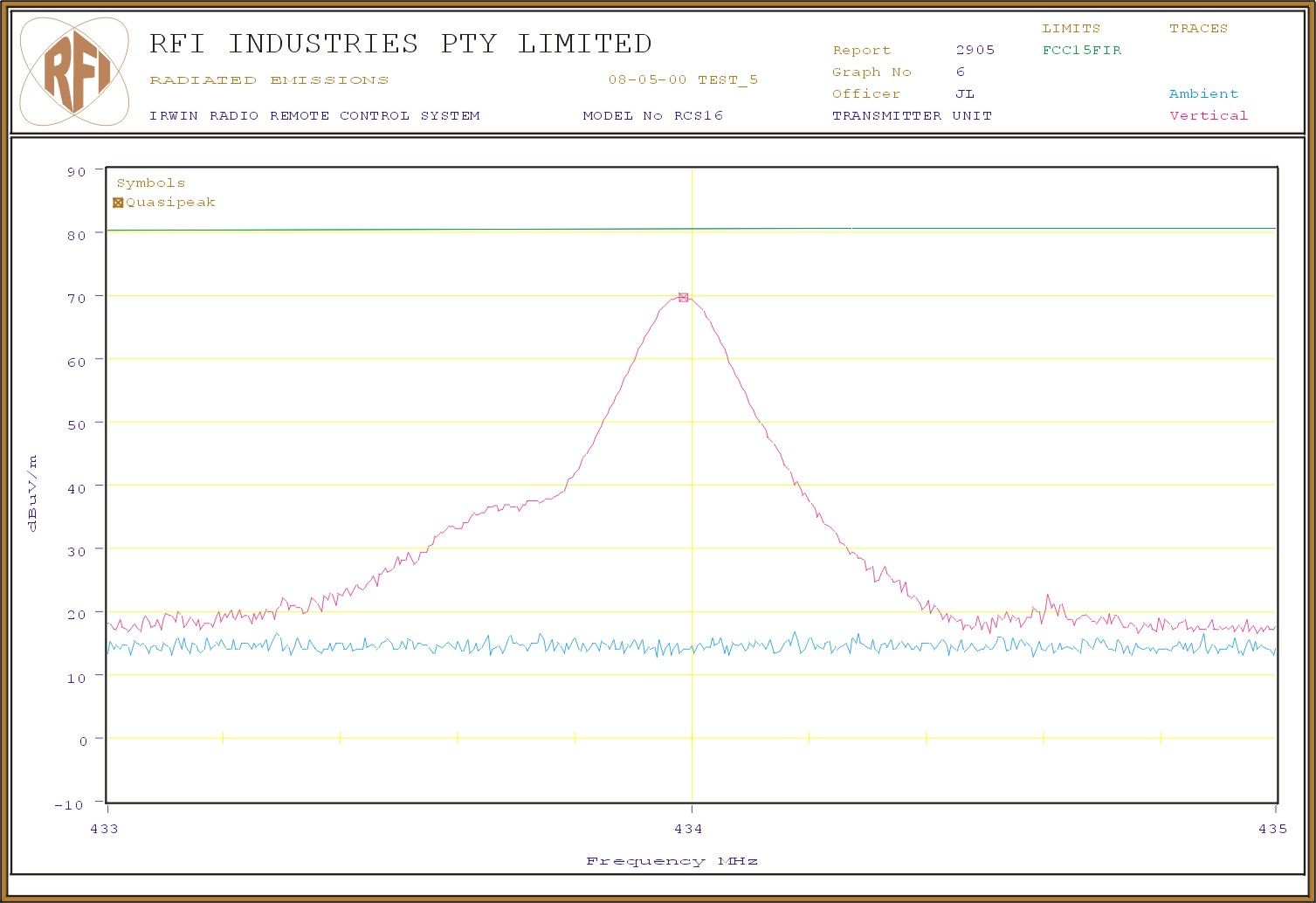
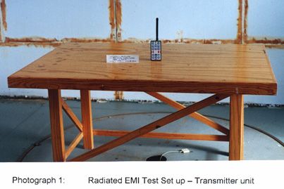
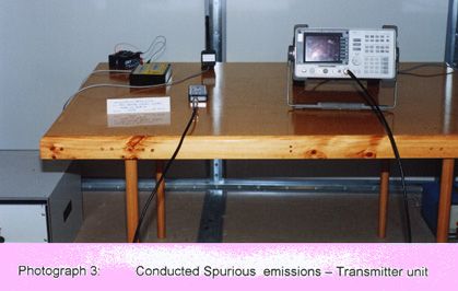
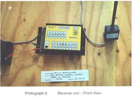
EMI TEST REPORT ON RADIO REMOTE CONTROL SYSTEM FOR IRWIN TECHNOLOGY PTY. LTD. R.F.I. INDUSTRIES TEST REPORT TL2905 May, 2000. R.F.I. Industries Test Report TL2905 Page 2 of 52 This document may not be reproduced except in full unless permission for the reproduction of an approved extract has been obtained in writing from RFI Industries. EMI TEST REPORT FOR IRWIN TECHNOLOGY PTY LTD. Administrative Data Specification :FCC Part 15 Subpart C – Intentional Radiators EN 300 220-1 V1.2.1 (1997-11) Electromagnetic Compatibility and Radio spectrum Matters (ERM); Short range devices; Technical characteristics and Test methods for radio equipment to be used in the 25MHz to 1000MHz frequency range with power level ranging up to 500mW; Part 1: Parameters intended for regulatory purposes. Test Sample:Radio remote control system Model No RCS16 Customer Contact:Mr. Irwin McRae, Irwin Technology Pty. Ltd., 3/25 Leslie Street, St. Kilda VIC 3183 Telephone: 018555527 Facsimile : 03 9527 5500 Test Dates:8 th and 9 th May, 2000. Test Officer:Jorge Lara O.A.T.S. - Supervisor Authorised by:Malcolm Mulcare - Senior Engineer Report Issued:May, 2000. Test Laboratory:R.F.I. Industries Pty. Limited, EMI/EMC Laboratories Unit 6/381 Bayswater Road BAYSWATER Vic. 3153 Phone:(03) 9720 8522 Fax :(03) 9720 8437 Distribution:Customer - Copies 1 and 2 R.F.I. Industries - Copy 3 R.F.I. Industries Test Report TL2905 Page 3 of 52 This document may not be reproduced except in full unless permission for the reproduction of an approved extract has been obtained in writing from RFI Industries. EMI TEST REPORT FOR IRWIN TECHNOLOGY PTY. LTD. 1.INTRODUCTION Radiated and Conducted Electromagnetic Interference (EMI) tests was performed on the Radio remote control system to determine compliance with the FCC Part 15 Subpart C and EN300 220-1 requirements. 2.TEST SAMPLE DETAILS The Equipment Under Test (EUT) was identified as: IRWIN RADIO REMOTE CONTROL SYSTEM Model No RCS16 (See Appendix B – EUT Description and Configuration) 3.TEST CONFIGURATION AND OPERATING CONDITIONS 3.1 Radiated and Conducted EMI tests were performed in accordance with customer specification. 3.2 Transmitter and Receiver units were tested separately. 3.3 To obtain the recorded values, the following modifications were performed to the EUT: Transmitter unit::3.3pF and 6.8pF connected between the output to antenna and antenna to ground respectively. Receiver unit:Software changed to “Low EMI” (Refer to Appendix C – Photographs) 4.DESCRIPTION OF MEASUREMENT FACILITIES AND EQUIPMENT 4.1Test Site The Open Area Test Site and conducted measurement facility used to collect the radiated and conducted EMI data, is located at Tooborac, near Heathcote, 100km north of Melbourne. 4.2Test Equipment Refer to Appendix A for EMI/EMC Test and Measurement Instruments List. R.F.I. Industries Test Report TL2905 Page 4 of 52 This document may not be reproduced except in full unless permission for the reproduction of an approved extract has been obtained in writing from RFI Industries. 5. TEST PROCEDURE - RADIATED EMISSIONS 5.1Range 2:30MHz – 1GHz 5.1.1 Radiated EMI was measured at a test distance of 3 metres at the Open Area Test Site using R.F.I. Industries EMI Measurement Software. 5.1.2 The measurements were performed automatically with a PC driving the analyser and plotter via the IEEE-488 BUS, to acquire, store and plot corrected field strength measurements over six frequency ranges. Range 130 - 85MHz Range 2 85 - 110MHz Range 3110 - 200MHz Range 4200 - 500MHz Range 5500 – 700MHz Range 6700 – 1000MHz 5.1.3 The EUT was tested in accordance with each configuration identified in Para. 3. 5.1.4 The EUT was slowly rotated in order to find the worst case emissions arrangement for one program loop. For both horizontal and vertical antenna polarization, the peak detector was set to MAX-HOLD and the range selected continuously scanned. The antenna height was varied from 1 to 4 metres and the turntable slowly rotated. The accumulated measurement data for both horizontal and vertical polarization, including all calibration parameters were then stored on disk. The six ranges were then combined and plotted onto one logarithmic graph of corrected field strength (dBμV/m) versus frequency. 5.1.5 The EMI Receiver was used to measure the quasi-peak value of significant emissions and the value manually plotted onto the graph. 5.1.6 The Fundamental Frequency and Spurious emissions limit are specified in Section 15.231 of the FCC Part 15 Subpart C standard. 5.1.7 A zoom measurement was performed to obtain the Fundamental Frequency measurements in accordance with the FCC Part 15 Subpart C and the EN300 220-1 requirements. 5.2Range 2:1.0GHz – 5.0GHz 5.1.1 Radiated EMI was measured at a test distance of 3 metres at the Open Area Test Site using R.F.I. Industries EMI Measurement Software. R.F.I. Industries Test Report TL2905 Page 5 of 52 This document may not be reproduced except in full unless permission for the reproduction of an approved extract has been obtained in writing from RFI Industries. 5.1.2 The measurements were performed automatically with a PC driving the analyser and plotter via the IEEE-488 BUS, to acquire, store and plot corrected field strength measurements over three (3) frequency ranges. Range 11000 - 2648MHz Range 2 2648 - 4200MHz Range 32648 - 5000MHz 5.1.3 The EUT was tested in accordance with each configuration identified in Para. 3. 5.1.4 The EUT was slowly rotated in order to find the worst case emissions arrangement for one program loop. For both horizontal and vertical antenna polarization, the peak detector was set to MAX-HOLD and the range selected continuously scanned. The antenna height was positioned to 1 metres and the turntable slowly rotated. The accumulated measurement data for both horizontal and vertical polarization, including all calibration parameters were then stored on disk. The three ranges were then combined and plotted onto one logarithmic graph of corrected fi…
Text truncated - open the document above for the full version.
Contact Information
Applicant
Irwin H Mc Rae(Managing Director)
Technical Contact
Non-Technical Contact
Irwin Technology Pty LtdIrwin H McRae
[email protected]61-3-95275500
Test Firm
RFI Industries Pty LimitedAndrew Whiteford
Technical Specifications
| # | Rule Parts | Frequency Range | Power Output | Tolerance |
|---|---|---|---|---|
| 1 | 15C | 433.92 MHz - 433.92 MHz | - | Hz |
Other Applications from Irwin Technology Pty Ltd
OZTRCS16RX
Aug 30, 2000CYY - Communications Receiver used w/Pt 15 Transmitter
Equipment Class
CYY - Communications Receiver used w/Pt 15 Transmitter