P27-SSCO5R0Carbon Monoxide Detector
Sercomm Corporation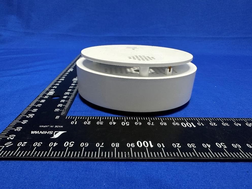
Click to zoom
Application Details
- Equipment Class
- PUB - Part 15 Unlicensed PCS Base Station
- Date of Grant
- Apr 12, 2023
- Application Purpose
- Original Equipment
- Date of Application
- Apr 10, 2023
- Equipment Note
- Carbon Monoxide Detector
- Frequency Range
- 1921.53600000 - 1928.44800000
- Company
- Sercomm Corporation
- Country
- Taiwan
Documents & Files
Document Text
Text extracted from the exhibit documents filed with the FCC. Open a document above to read the original.
Users Manual
1 SSCO5R0-29 Carbon Monoxide ALARM Installation Guide The SSCO5R0-29 is a carbon monoxide alarm that is designed to detect high CO concentration. This device can provide more time by making alarms for you and your family to escape from high CO concentration hazard. A DECT ULE module is installed and can transmit events to cloud service via a DECT ULE Base. Specification Batter Type CR123A x2 Operating Temperature 0 C to 40 C (40° - 100°F) Operating Humidity 10% to 95% Non-condensing Alarm Audibility CO: T4 Alarm At least 85 dB at 10 feet Dimention 125mm (diameter) x 43mm (depth) LED Behavior Enrollment . Search: Flash Blue . Enroll Success: Solid Blue Test . Test Button: Solid Yellow . Out of Range: Flash Green . Connected to Base: Solid Green Battery: . Low Battery: Slow Flash Red (100ms every 20s) . Critical Low Battery: Fast Flash Red (100ms every 5s) Alarm . Fast Flash Red Install Battery 1. Open battery cover to install 2 batteries and the device will start to operate. 2. Test the smoke alarm by pressing “Test Button” to assure the unit is functioning correctly. The horn start sounding when the test button is long pressed. Silence If the device is alarming, press the “Test /Silence” button will have it silenced. Locations for installation Selecting a suitable location is critical for the CO detector. The Consumer Product Safety Commission (CPSC) recommends to use at least one CO detector per household, located as near as possible to sleeping areas of the home, because the human body is most vulnerable to the effects of CO gas during sleeping hours. For added protection, install additional CO detectors in every bedroom and on every level of your home. If your bedroom hallway is longer than 14 meters (40 feet), install a CO detector at BOTH ends of the hallway. Install an additional detector 6 meters (20 feet) away from the furnace or fuel burning heat source. For maximum protection, the detector should also be located outside primary sleeping areas or at each level of your home. Mount the detector on a firm wall or ceiling. 2 Do not place the device in the following areas: • In locations where temperature may be below O”C (14°F) or above 40°C (104°F). • In locations where the relative humidity exceeds 93% • Near paint thinner fumes. • Near air conditioners, furnaces, stoves, fireplaces and any other ventilation source that may interfere with CO gas entering the detector. • In locations where furniture or draperies may obstruct the air flow. • In exhaust streams from gas engines, vents, flues or chimneys. • Where dirt or dust could collect and block the sensor and prevent it from working. • In locations that can be reached by children. • In turbulent air from ceiling fans. • In close proximity to an automobile exhaust pipe - this will damage the detector. Ceiling Mounting 1. Choose a flat and solid ceiling to install the device. 2. Draw a four inches horizontal line at the place where you are going to install the device. 3. Draw 2 marks to locate the screws. 4. Drill two holes at the marks and insert screws and wall plugs. 5. Attach the bracket to the ceiling by using the supplied two screws and wall plugs. 6. Attach the device onto the mounting bracket and turn it clockwise to fix it into place. Make sure it is securely attached to the mounting bracket. Weekly Testing 1. Never use an open flame of any kind to test this unit. You might accidentally damage or set fire to the unit or to your home. 2. If the alarm ever fails to test properly, replace it immediately. 3. It is important to test this unit every week to make sure it is working properly. Using the Test/Silence button is the recommended way to test this Smoke Alarm. Press and hold the Test/Silence button until the alarm sounds (the unit may continue to alarm for a few seconds after you release the button). If it does not alarm, make sure the smoke alarm battery is installed and test it again. If it still does not alarm, replace it immediately. During testing you will hear a loud, repeating horn pattern: 3 beeps, pause, 3 beeps, pause. Red LED flashes rapidly. Regular Maintenance 1. Clean the smoke alarm at least once a month. Gently vacuum the outside of the smoke sensing chamber using household vacuum’s soft brush attachment. A can of compressed air may also be used to blow out dirt inside sensing chamber. 2. Test the smoke alarm after cleaning. 3. Never use water, cleaners or solvents since they may damage the unit. 3 FCC Statement This equipment has been tested and found to comply with the limits for a Class B digital device, pursuant to Part 15 of the FCC Rules. These limits are designed to provide reasonable protection against harmful interference in a residential installation. This equipment generates, uses and can radiate radio frequency energy and, if not installed and used in accordance with the instructions, may cause harmful interference to radio communications. However, there is no guarantee that interference will not occur in a particular installation. If this equipment does cause harmful interference to radio or television reception, which can be determined by turning the equipment off and on, the user is encouraged to try to correct the interference by one of the following measures: • Reorient or relocate the receiving antenna. • Increase the separation between the equipment and receiver. • Connect the equipment into an outlet on a circuit different from that to which the receiver is connected. • Consult the dealer or an experienced radio/TV technician for help. The FCC ID for this device is P27-SSCO5R0 You are cautioned that changes or modifications not expressly approved by the party responsible for compliance could void your authority to operate the equipment. This device complies with Part 15 of the FCC Rules. Operation is subject to the following two conditions: (1) This device may not cause harmful interference, and (2) This device must accept any interference received, including interference that may ca…
Text truncated - open the document above for the full version.
Attestation Statements
FederalCommunicationsCommission AuthorizationandEvaluationDivision 7435OaklandMillsRoad Columbia,MD21046 USA Date:March30,2023 Ref:AttestationStatementsPart2.911(d)(5)(i)Filing FCCID:P27-SSCO5R0 SercommCorporation(“theapplicant”)certifiesthattheequipmentforwhichauthorizationissoughtis not“covered”equipmentprohibitedfromreceivinganequipmentauthorizationpursuanttosection 2.903oftheFCCrules. Sincerely, Name:NickWu Title:Manager Email:[email protected] Date:March30,2023
Attestation Statements
FederalCommunicationsCommission AuthorizationandEvaluationDivision 7435OaklandMillsRoad Columbia,MD21046 USA Date:March30,2023 Ref:AttestationStatementsPart2.911(d)(5)(ii)Filing FCCID:P27-SSCO5R0 SercommCorporation(“theapplicant”)certifiesthat,asofthedateofthefilingoftheapplication,the applicantisnotidentifiedontheCoveredListasanentityproducing“covered”equipment. Sincerely, ____ Name:NickWu Title:Manager Email:[email protected] Date:March30,2023
Attestation Statements
U.S. Agent for Service of Process Attestation To the attention of Federal Communications Commission Authorization and Evaluation Division U.S. Agent Company Name: TianHeng Consulting, LLC FRN: 0033401258 Contact Name: Hualing Dong Street Address: 392 Andover Street, Wilmington, MA 01887, United States Telephone No: +1 (617) 997-4010 Email: [email protected] This letter is to confirm that we have accepted the responsibility to act as the designated U.S. Agent for service of process as required by §2.911(d)(7) on behalf of the Applicant noted below. U.S. Agent Signature: Date:2023-03-30 Signed byHualing Dong Applicant Company name: Sercomm Corporation FRN: 0015548027 FCC ID: :P27-SSCO5R0 Contact Name: Nick Wu Street Address: 8F, No. 3-1, YuanQu St, NanKang City/Province/Zip: Taipei, Taiwan, 115 Telephone No:+886-2-2655-3988 Email:[email protected] ThisletteristoconfirmthattheApplicanthasdesignatedtheU.SAgentnotedaboveforthe purposeofacceptingserviceofprocessontheirbehalfasrequiredby§2.911(d)(7).The Applicantfurtheracknowledgesacceptancetomaintainanagentfornolessthanoneyearafter thegranteehasterminatedallmarketingandimportationortheconclusionofanyCommission- relatedproceedinginvolvingtheequipment. ApplicantSignature: Date:2023-03-30 SignedbyNickWu
Cover Letter(s)
ConfidentialityRequestLetter FederalCommunicationsCommission AuthorizationandEvaluationDivision FCCID:P27-SSCO5R0 PursuanttoSections0.457and0.459oftheCommission’sRules,weherebyrequest confidentialtreatmentofinformationaccompanyingthisapplicationasoutlined below: 1.BlockDiagram 2.Schematics 3.OperationalDescription Theabovematerialscontaintradesecretsandproprietaryinformationnotcustomarily releasedtothepublic.Thepublicdisclosureofthesemattersmightbeharmfultothe applicantandprovideunjustifiedbenefitstoitscompetitors. TheapplicantunderstandsthatpursuanttoRule0.457,disclosureofthisapplication andallaccompanyingdocumentationwillnotbemadebeforethedateoftheGrant forthisapplication. Sincerely, Name:NickWu Title:Manager Email:[email protected] Date:March31,2023
Cover Letter(s)
DeclarationofAuthorization We Name:SercommCorporation Address:8F,No.3-1,YuanQuSt.,NanKang,Taipei115,Taiwan,R.O.C. Declarethat: NameRepresentativeofagent:MarlinChen AgentCompanyname:MRTTechnology(Suzhou)Co.,Ltd Address:D8Building,YouxinIndustrialPark,No.2 Tian'edangRd.,WuzhongEconomicDevelopment Zone City:Suzhou Country:China isauthorizedtoapplyforCertificationofthefollowingproduct(s): Product: CarbonMonoxideDetector FCCID:P27-SSCO5R0 ModelNo.:SSCO5R0-29xxxxx (the1stxshouldbe"blank"or"-";therestxcould be0to9,AtoZ,atoz,"blank"or"-",forthe marketingpurpose) Sincerely, __ Name:NickWu Title:Manager Email:[email protected] Date:March30,2023
Cover Letter(s)
FederalCommunicationsCommission AuthorizationandEvaluationDivision Date:March30,2023 ConfidentialityRequest FCCID:P27-SSCO5R0 PursuanttoSections0.457and0.459ofthecommission'srules,werequestshort-term confidentialtreatmentforthefollowinginformationuntil180daysaftertheGrantDateof EquipmentAuthorizationinordertoensuresensitivebusinessinformationremains confidentialuntiltheactualmarketingofthedevice: Externalphotos TestSetupphotos UserManual InternalPhotos Thankyou, Sincerelyyours, Name:NickWu Title:Manager Email:[email protected] Date:March31,2023
External Photos
Report No.: 2303RSU033-UE 1 of 2 EUT Photograph (1) EUT Photo (2) EUT Photo Report No.: 2303RSU033-UE 2 of 2 (3) EUT Photo (4) EUT Photo
Internal Photos
Report No.: 2303RSU033-UE 1 of 6 EUT Photograph (1) EUT Photo (2) EUT Photo Report No.: 2303RSU033-UE 2 of 6 (3) EUT Photo (4) EUT Photo Report No.: 2303RSU033-UE 3 of 6 (5) EUT Photo (6) EUT Photo Report No.: 2303RSU033-UE 4 of 6 (7) EUT Photo (8) EUT Photo Report No.: 2303RSU033-UE 5 of 6 (9) EUT Photo (10) EUT Photo Report No.: 2303RSU033-UE 6 of 6 (11) EUT Photo (12) EUT Photo
RF Exposure Info
MRT Technology (Suzhou) Co., Ltd Report No.: 2303RSU033-U3 Phone: +86-512-66308358 Report Version: V01 Web: www.mrt-cert.com Issue Date: 2023-04-06 Template Version:0.0 1 of 12 RF Exposure Evaluation Declaration FCC ID: P27-SSCO5R0 Applicant: Sercomm Corporation Product: Carbon Monoxide Detector Model No.: SSCO5R0-29xxxxx (the 1st x should be "blank" or "-"; the rest x could be 0 to 9, A to Z, a to z, "blank" or "-", for the marketing purpose) Brand Name: ADT FCC Classification: Unlicensed PCS Base Station (PUB) FCC Rule Part(s): FCC Part 2.1091 Received Date 2023-03-16 Reviewed By: Approved By: The test results relate only to the samples tested. The test results shown in the test report are traceable to the national/international standards through the calibration of the equipment and evaluated measurement uncertainty herein. The test report shall not be reproduced except in full without the written approval of MRT Technology (Suzhou) Co., Ltd. Report No.: 2303RSU033-U3 2 of 12 Revision History Report No. Version Description Issue Date Note 2303RSU033-U3 Rev. 01 Initial Report 2023-04-06 Valid Report No.: 2303RSU033-U3 3 of 12 CONTENTS Description Page 1. General Information ................................................................................................................................. 4 1.1. Applicant ........................................................................................................................................ 4 1.2. Manufacturer .................................................................................................................................. 4 1.3. Testing Facility ............................................................................................................................... 4 1.4. Product Information........................................................................................................................ 5 1.5. Radio Specification ........................................................................................................................ 5 1.6. Antenna Details .............................................................................................................................. 5 1.7. Applied Standards.......................................................................................................................... 6 2. RF Exposure Evaluation ......................................................................................................................... 7 2.1. Test Limits ...................................................................................................................................... 7 2.1. Test Exemptions ............................................................................................................................. 8 2.2. Test Result ................................................................................................................................... 11 Appendix A - EUT Photograph ...................................................................................................................... 12 Report No.: 2303RSU033-U3 4 of 12 1. General Information 1.1. Applicant Sercomm Corporation 8F, No. 3-1, YuanQu St., NanKang, Taipei 115, Taiwan, R.O.C. 1.2. Manufacturer Sercomm Corporation 8F, No. 3-1, YuanQu St., NanKang, Taipei 115, Taiwan, R.O.C. 1.3. Testing Facility Test Site – MRT Suzhou Laboratory Laboratory Location (Suzhou - Wuzhong) D8 Building, No.2 Tian’edang Rd., Wuzhong Economic Development Zone, Suzhou, China Laboratory Location (Suzhou - SIP) 4b Building, Liando U Valley, No.200 Xingpu Rd., Shengpu Town, Suzhou Industrial Park, China Laboratory Accreditations A2LA: 3628.01 CNAS: L10551 FCC: CN1166 ISED: CN0001 VCCI: R-20025 G-20034 C-20020 T-20020 R-20141 G-20134 C-20103 T-20104 Test Site – MRT Shenzhen Laboratory Laboratory Location (Shenzhen) 1G, Building A, Junxiangda Building, Zhongshanyuan Road West, Nanshan District, Shenzhen, China Laboratory Accreditations A2LA: 3628.02 CNAS: L10551 FCC: CN1284 ISED: CN0105 Test Site – MRT Taiwan Laboratory Laboratory Location (Taiwan) No. 38, Fuxing 2nd Rd., Guishan Dist., Taoyuan City 333, Taiwan (R.O.C.) Laboratory Accreditations TAF: L3261-190725 FCC: 291082, TW3261 ISED: TW3261 Report No.: 2303RSU033-U3 5 of 12 1.4. Product Information Product Name Carbon Monoxide Detector Model No. SSCO5R0-29xxxxx (the 1st x should be "blank" or "-"; the rest x could be 0 to 9, A to Z, a to z, "blank" or "-", for the marketing purpose) Serial No. ADT Antenna Information Refer to section 1.6 Working Voltage Battery CR123A x 2 Accessories Battery Model: CR123A Output: 1500mAh Remark: 1. The information of EUT was provided by the manufacturer, and the accuracy of the information shall be the responsibility of the manufacturer. 2. The difference of models just marketing requirement, all of hardware and software are the same. We chose the Model SSCO5R0-29 to do RF testing. 1.5. Radio Specification Frequency Range 1921.536 ~ 1928.448MHz Channel Number 5 RF Channels, 5*12 = 60 TDMA Duplex Channels Type of Modulation GFSK Max. Number of timeslots 24 Max. Number of active timeslots 1 (full slot – 416.7μs, long slot – 694.4μs) 1.6. Antenna Details Antenna Type Frequency Band (MHz) T X Paths Max Antenna Gain (dBi) PIFA 1920 ~ 1930 1 2.48 Report No.: 2303RSU033-U3 6 of 12 1.7. Applied Standards According to the specifications of the manufacturer, the EUT must comply with the requirements of the following standards: ⚫ FCC Part 2.1091 ⚫ KDB 447498 D04 Interim General RF Exposure Guidance v01 Report No.: 2303RSU033-U3 7 of 12 2. RF Exposure Evaluation 2.1. Test Limits According to FCC §1.1310: The criteria listed in the following table shall be used to evaluate the environment impact of human exposure to radio frequency (RF) radiation as specified in §1.1307(b) LIMITS FOR MAXIMUM PERMISSIBLE EXPOSURE (MPE) Frequency Range (MHz) Electric Field Strength (V/m) Magnetic Field Strength (A/m…
Text truncated - open the document above for the full version.
Test Report
MRT Technology (Suzhou) Co., Ltd Report No.: 2303RSU033-U2 Phone: +86-512-66308358 Report Version: V01 Web: www.mrt-cert.com Issue Date: 2023-04-06 Template Version:0.0 1 of 53 RF MEASUREMENT REPORT FCC ID: P27-SSCO5R0 Applicant: Sercomm Corporation Product: Carbon Monoxide Detector Model No.: SSCO5R0-29xxxxx (the 1st x should be "blank" or "-"; the rest x could be 0 to 9, A to Z, a to z, "blank" or "-", for the marketing purpose) Brand Name: ADT FCC Classification: Unlicensed PCS Base Station FCC Rule Part(s): FCC Part 15, Subpart D Received Date 2023-03-16 Result: Complies Test Date: 2023-03-17 ~ 2023-03-28 Reviewed By: Approved By: The test results relate only to the samples tested. This equipment has been shown to be capable of compliance with the applicable technical standards as indicated in the measurement report and was tested in accordance with the measurement procedures specified in ANSI C63.17. Test results reported herein relate only to the item(s) tested. The test report shall not be reproduced except in full without the written approval of MRT Technology (Suzhou) Co., Ltd. Report No.: 2303RSU033-U2 2 of 53 Revision History Report No. Version Description Issue Date Note 2303RSU033-U2 Rev. 01 Initial Report 2023-04-06 Valid Report No.: 2303RSU033-U2 3 of 53 CONTENTS Description Page 1. General Information .................................................................................................................................. 6 1.1. Applicant......................................................................................................................................... 6 1.2. Manufacturer .................................................................................................................................. 6 1.3. Testing Facility ................................................................................................................................ 6 1.4. Product Information ........................................................................................................................ 7 1.5. Radio Specification ........................................................................................................................ 8 1.6. Working Frequencies ..................................................................................................................... 8 1.7. Description of Available Antennas .................................................................................................. 8 2. Test Configuration .................................................................................................................................... 9 2.1. Test Mode ...................................................................................................................................... 9 2.2. Test System Connection Diagram ................................................................................................. 9 2.3. Test System Details ....................................................................................................................... 9 2.4. Test Environment Condition ........................................................................................................... 9 2.5. Labeling Requirements ................................................................................................................ 10 2.6. Automatic Discontinuation of Transmission ................................................................................. 10 3. Antenna Requirements .......................................................................................................................... 11 4. Measuring Instrument ............................................................................................................................ 12 5. Measurement Uncertainty ...................................................................................................................... 13 6. Test Result ............................................................................................................................................... 14 6.1. Summary ...................................................................................................................................... 14 6.2. AC Power Line Conducted Measurement Emissions .................................................................. 15 6.2.1. Test Limit .................................................................................................................................. 15 6.2.2. Test Setup ................................................................................................................................ 15 6.2.3. Test Result ............................................................................................................................... 15 6.3. Emission Bandwidth Measurement.............................................................................................. 16 6.3.1. Test Limit .................................................................................................................................. 16 6.3.2. Test Procedure used ................................................................................................................ 16 6.3.3. Test Setup ................................................................................................................................ 16 6.3.4. Test Result ............................................................................................................................... 17 6.4. Peak Power Output ...................................................................................................................... 18 6.4.1. Test Limit .................................................................................................................................. 18 6.4.2. Test Procedure Used ...........................................................................................…
Text truncated - open the document above for the full version.
Test Report
Mar. 21, 2023 ADT / SSCO5R0-29 Internal Antenna Data Sheet Confidential & Proprietary 2 Outline •Antenna Infomation •Antenna Structure & Placement •Return Loss •Radiation Pattern •Peak Gain & Efficiency Confidential & Proprietary 3 Antenna Infomation IteamDescription Model numberSD-CO09_Antenna Part number617211ZP ApplicationDECT Antenna TypePIFA ManufacturerSerComm Corporation Address8F, No. 3-1, YuanQu St. Taipei, Taiwan 115 R.O.C. Operating Band1850 ~ 1950 MHz Return Loss (dB)Used for device > 10dB Efficiency (%)> 60% Impedance (ohm)50Ω Cable TypeNA ConnectorNA Confidential & Proprietary 4 Antenna Structure & Placement AntOperating BandTypeMaterial FeedingDimension DECT1850 ~ 1950 MHzPIFAMetalTrace31 x 7 x 13.5 mm 3 Confidential & Proprietary 5 Return Loss Confidential & Proprietary 6 Return Loss Confidential & Proprietary 7 Radiation Pattern X Y Z Confidential & Proprietary 8 Peak Gain & Efficiency Frequency (MHz) DECT Antenna Efficiency (%)Peak Gain (dBi) 185070.362.09 188071.412.18 190071.222.48 192074.132.42 195070.692.19 Confidential & Proprietary 9 Summary •Antenna Performance is very good.
Test Setup Photos
Report No.: 2303RSU033-UT RF Test Setup Photo Description: Radiated Spurious Emission Test Setup for Below 1GHz Description: Radiated Spurious Emission Test Setup for Above 1GHz Report No.: 2303RSU033-UT Description: Conducted Test Setup
Contact Information
Applicant
Nick Wu(Engineer)
Technical Contact
MRT Technology (Suzhou) Co., LtdRobin Wu
[email protected]86-512-66308358
D8 Building, Youxin Industrial Park, · Suzhou · China
Non-Technical Contact
MRT Technology (Suzhou) Co., LtdRobin Wu
[email protected]0512-66308358
Test Firm
MRT Technology (Suzhou) Co., Ltd.Mr. Marlin Chen
[email protected]8651266308358
Technical Specifications
| # | Rule Parts | Frequency Range | Power Output |
|---|---|---|---|
| 1 | 15D | 1.92 GHz - 1.93 GHz | 91.40 mW |
Other Applications from Sercomm Corporation
P27-MOTIONZW60R0
Aug 04, 2026WIRELESS PIR MOTION SENSOR
Equipment Class
DTS - Digital Transmission SystemP27-SCP5173P
Dec 24, 2025Moso Canopy 5GOD2
Equipment Class
CBD - Citizens Band Category A and B DevicesP27-TPM530
Nov 24, 2025CATM1 Module
Equipment Class
PCB - PCS Licensed TransmitterP27MQIO
Sep 16, 2025Mqio 9W
Equipment Class
DTS - Digital Transmission SystemP27LORAAREAV2
Jul 25, 2024MachineQ Area 8C V2 LoRaWAN Gateway
Equipment Class
PCB - PCS Licensed Transmitter