P27CB801M802.11g Wireless PC Card
Sercomm Corporation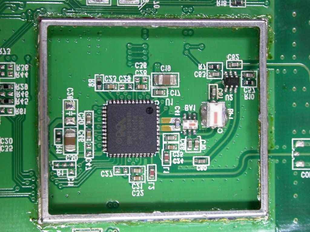
Click to zoom
Application Details
- Equipment Class
- DTS - Digital Transmission System
- Date of Grant
- Mar 16, 2005
- Application Purpose
- Original Equipment
- Date of Application
- Mar 16, 2005
- Equipment Note
- 802.11g Wireless PC Card
- Frequency Range
- 2412.00000000 - 2462.00000000
- Company
- Sercomm Corporation
- Country
- Taiwan
Documents & Files
Document Text
Text extracted from the exhibit documents filed with the FCC. Open a document above to read the original.
Users Manual
IEEE802.11g Wireless PC Card User Guide Regulatory Approvals FCC Statement This equipment has been tested and found to comply with the limits for a Class B digital device, pursuant to Part 15 of the FCC Rules. These limits are designed to provide reasonable protection against harmful interference in a residential installation. This equipment generates, uses and can radiate radio frequency energy and, if not installed and used in accordance with the instructions, may cause harmful interference to radio communica- tions. However, there is no guarantee that interference will not occur in a particular installation. If this equipment does cause harmful interference to radio or television reception, which can be determined by turning the equipment off and on, the user is encouraged to try to correct the interference by one of the following measures: Reorient or relocate the receiving antenna. Increase the separation between the equipment and receiver. Connect the equipment into an outlet on a circuit different from that to which the receiver is connected. Consult the dealer or an experienced radio/TV technician for help. To assure continued compliance, any changes or modifications not expressly approved by the party responsible for compliance could void the user's authority to operate this equipment. (Example - use only shielded interface cables when connecting to computer or peripheral devices). Channel The Wireless Channel sets the radio frequency used for communication. Access Points use a fixed Channel. You can select the Channel used. This allows you to choose a Channel which provides the least interference and best performance. In the USA and Canada, 11 channel are available. If using multiple Access Points, it is better if adjacent Access Points use different Channels to reduce interference. In "Infrastructure" mode, Wireless Stations normally scan all Channels, looking for an Access Point. If more than one Access Point can be used, the one with the strongest signal is used. (This can only happen within an ESS.) If using "Ad-hoc" mode (no Access Point), all Wireless stations should be set to use the same Channel. However, most Wireless stations will still scan all Channels to see if there is an existing "Ad-hoc" group they can join. This device has been tested and meets the FCC RF exposure guidelines. The maximum SAR value reported is 0.071 w/kg Table of Contents SECTION 1. INTRODUCTION................................................................................................................................3 1.1 OVERVIEW..............................................................................................................................................................3 1.2 INSTALLATION.......................................................................................................................................................3 1.2.1 Adapter Windows Driver............................................................................................................................3 1.2.2 Adapter Configuration Utility...................................................................................................................3 1.3 SYSTEM REQUIREMENTS.....................................................................................................................................3 1.4 PACKAGE CONTENTS............................................................................................................................................3 SECTION 2. DRIVER INSTALLATION...............................................................................................................4 2.1 INSTALLING THE WINDOWS XP DRIVER............................................................................................................4 2.2 INSTALLING THE WINDOWS 2000 DRIVER........................................................................................................6 2.3 INSTALLING THE WINDOWS 98SE DRIVER.....................................................................................................11 2.4 INSTALLING THE WINDOWS ME DRIVER........................................................................................................15 SECTION 3. CONFIGURATION UTILITY INSTALLATION....................................................................17 INSTALLING THE CONFIGURATION UTILITY...........................................................................................................17 SECTION 3. CONFIGURATION UTILITY.......................................................................................................19 3.1 OVERVIEW............................................................................................................................................................19 3.1.1 Windows XP Users....................................................................................................................................19 3.1.2 Running the Configuration Utility..........................................................................................................20 3.1.3 Tray Status Icons.......................................................................................................................................20 3.1.4 Configuration Utility Window.................................................................................................................20 3.1.5 Auto Link Feature......................................................................................................................................20 3.1.6 WPA Configuration...................................................................................................................................20 3.2 NETWORK STATUS TAB......................................................................................................................................22 3.2.1 Select Profile........................................................................…
Text truncated - open the document above for the full version.
Cover Letter(s)
Exclusive Certification Corp. 4F-2, No. 28, Lane 78, Xing-Ai Rd. Nei-hu, Taipei City 114 Taiwan R.O.C 11478284-2F Tel: 886-2-2792-3366 Fax: 886-2-2792-1100 To whom it may concern: The enclosed documents constitute a formal submittal and application for a Grant of Equipment Authorization pursuant to Subpart C of Part 15 of FCC rules (CFR47) regarding IEEE802.11g Wireless PC Card for the SerComm model CB801M. Data within this report demonstrates that the equipment tested complied with the FCC limits for intentional radiators. Exclusive Certificate Corp. (ECC), as duly authorized agent prepared this submittal. A copy of the letter of our appointment as agent is enclosed. If there are any questions or if further information is needed, please contact ECC for assistance. Ivy Chen TEL: +886-2-2792-3366 # 204 FAX: +886-2-2792-1100 E-mail: [email protected]
Cover Letter(s)
American Telecommunications Certification Body Inc. 6731 Whittier Ave, McLean, VA 22101 January 27, 2005 RE: SerComm Corporation FCC ID: P27CB801M I have a few comments on this Application. Depending on your responses, kindly understand there may be additional comments. 1.) The Manual is confusing: Although it states that only Ch 1-11 are for use in North America, it leaves open the possibility that when infrastructure mode, transmitting outside of the permitted channel set may be possible. This is not permitted no mater how brief and should be addressed. Would this device ever possibly transmit on channels 12 or 13 in North America? 2.) The SAR value quoted in the Manual does not match the measured value in the SAR report. Please correct. 3.) The Test Report in Section 1.11 identifies 20cm as the separation distance to be used by the end user from this device. This is not appropriate since a SAR report has also been submitted for evaluation. Kindly address. William H. Graff President and Director of Engineering mailto: [email protected] The items indicated above must be submitted before processing can continue on the above referenced application. Failure to provide the requested information may result in application termination. Correspondence should be considered part of the permanent submission and may be viewed from the Internet after a Grant of Equipment Authorization is issued. Please do not respond to this correspondence using the email reply button. In order for your response to be processed expeditiously, you must submit your documents through the AmericanTCB.com website. Also, please note that partial responses increase processing time and should not be submitted. Any questions about the content of this correspondence should be directed to the sender.
Cover Letter(s)
1 William Graff From: Ivy [[email protected]] Sent: Thursday, March 17, 2005 3:33 PM To: Major; ATCB; Bill Cc: Jerry; Eric Subject: Fw: P27CB801M (resend RT) Attachments: ATCB Comments 01272005.pdf ATCB Comments 01272005.pdf (45... Hi Bill, Sorry for the late response. About your comment No.1, the answer is No, this device can not be used on channels 12-13 in America. No. 2, I just uploaded a new manual to your website, please check. No. 3. I have removed the 20 cm sentence in the report and uploaded it to your website, please check. Thank you very much. Best Regards, Ivy Chen ----- Original Message ----- From: "William Graff" <[email protected]> To: <[email protected]> Cc: "'Major (E-mail)'" <[email protected]> Sent: Wednesday, February 23, 2005 2:21 AM Subject: P27CB801M (resend RT) > Ivy, > > I still have not received any filings from you on this project at the ATCB > server. Is there any problem? > > I am on travel this week, but if there is anything Major or myself can do to > help you out, please let me know. > > Bill > > ~~~~~~~~~~~~~~~~~~~~~~~~~~~~~~ > ~ William H. Graff, NARTE Certified > ~ President and Director of Engineering > ~ AmericanTCB, Inc. > ~ 6731 Whittier Ave, > ~ McLean, VA 22101 > ~ mailto:[email protected] > ~ Direct Phone: (703) 880-6337 > ~ Direct Mobile: (480) 459-6706 > ~ Corporate Phone: (703) 847-4700 > ~ Corporate FAX: (703) 847-6888 > ~ Taiwan Mobile: +886 920399260 > ~~~~~~~~~~~~~~~~~~~~~~~~~~~~~~ > 2
ID Label/Location Info
64. 50 mm 4 0 . 0 0 m m R25x4 IEEE802.11g Wireless PC Card CB801M FCC ID: P27CB801M
Internal Photos
Internal Photos
Operational Description
CB801M Operation Principle (1). CPU, U3, The Marvell 88W8335 is one of 802.11 a/b/g MAC/Baseband processor ; Support Cardbus/PC card/Compact Flash/miniPCI/PCI host interfaces ; 10 GPIOs pin , Flexible GPIO interface with (LED) drivers to indicate TX/RX activities. It’s on-chip A/D and D/A converters for I/Q channels . Supports short preamble and antenna diversity . Supports 6,9,12,18,24,36,48,54 Mbps for OFDM , 1,2,5.5,11 Mbps for DSSS . (2). 2.4GHz Transceiver, U1, The Marvell 88W8010 operates in the 2.4GHz frequency bands designed for IEEE 802.11g WLAN system or other WLAN application operating in 2.4GHz ISM band . The transceiver integrate all RF to baseband receive and transmit functions. Support power management/standby mode. It’s contain all the active circuitry to support physical layer functions for both receive and transmit operation. (3). Power part: there are one regulator used on the board. U9, AME8805LEFT is used to transfer DC 3.3V to DC 1.5V 600 mA . (4). LED part: LED Color Description Power Green-Yellow On – Power is ready Off - Power is not ready Link Green-Yellow On – Radio link Off – Radio not link (5). Band-Pass Filters, BP1, ACX BF3225-B2R4CAAT/, Freq. Range: 2.4~2.5GHz; IL@BW: 2.5dB max (6). GaAs MMIC SPDT Switch, U2, AS179-92 , features low insertion loss with and positive voltage operation with very low DC power consumption.
RF Exposure Info
Report No. : ES/2005/10001 Page : 1 of 48 TEST REPORT Equipment Under Test : IEEE802.11g Wireless PC card Model No. : CB801M FCC ID : P27CB801M Applicant : SerComm Corporation Address of Applicant : 8F,No.3-1, YunaQu St., Nankang, Taipei 115, Taiwan, R.O.C Date of Receipt : 2005.01.11 Date of Test(s) : 2005.01.13-2005.01.14 Date of Issue : 2005.01.20 Standards: FCC OET Bulletin 65 supplement C, ANSI/IEEE C95.1, C95.3, IEEE 1528-2003 In the configuration tested, the EUT complied with the standards specified above. Remarks: This report details the results of the testing carried out on one sample, the results contained in this test report do not relate to other samples of the same product. The manufacturer should ensure that all products in series production are in conformity with the product sample detailed in this report. This report may only be reproduced and distributed in full. If the product in this report is used in any configuration other than that detailed in the report, the manufacturer must ensure the new system complies with all relevant standards. Any mention of SGS Taiwan E&E Services or testing done by SGS Taiwan E&E Services in connection with distribution or use of the product described in this report must be approved by SGS Taiwan E&E Services in writing. Tested by : Dikin Yang Date : 2005.01.20 Approved by : Robert Chang Date : 2005.01.20 Report No. : ES/2005/10001 Page : 2 of 48 Contents 1. General Information 1.1 Testing Laboratory 4 1.2 Details of Applicant 4 1.3 Description of EUT(s) 4 1.4 Test Environment 5 1.5 Operation description 5 1.6 Evaluation procedures 6 1.7 The SAR Measurement System 7 1.8 System Components 8 1.9 SAR System Verification 9 1.10 Tissue Simulant Fluid for the Frequency Band 2.4 to 2.5 GHz 10 1.11 Test Standards and Limits 11 2. Instruments List 13 3. Summary of Results 14 4. Measurements 16 802.11b Configuration 1 4.1.1 Vertical position, lowest channel 16 4.1.2 Vertical position, middle channel 17 4.1.3 Vertical position, highest channel 18 Configuration 2 4.1.4 Horizontal position, lowest channel 19 4.1.5 Horizontal position, middle channel 20 4.1.6 Horizontal position, highest channel 21 802.11g Configuration 1 4.2.1 Vertical position, lowest channel 22 4.2.2 Vertical position, middle channel 23 4.2.3 Vertical position, highest channel 24 Configuration 2 4.2.4 Horizontal position, lowest channel 25 4.2.5 Horizontal position, middle channel 26 4.2.6 Horizontal position, highest channel 27 System Verification 4.3.1 S ystem Performance Validation 28 APPENDIX 1. Photographs of Test Setup 30 2. Photographs of EUT 34 3. Probe Calibration certificate 36 Report No. : ES/2005/10001 Page : 3 of 48 4. Uncertainty Analysis 40 5. Phantom description 41 6. System Validation from Original equipment supplier 42 7. Z-axis Plot 43 Report No. : ES/2005/10001 Page : 4 of 48 1. General Information 1.1 Testing Laboratory SGS Taiwan Ltd. 1F, No. 134, Wukung Road, Wuku industrial zone Taipei county , Taiwan , R.O.C. Telephone : +886-2-2299-3279 Fax : +886-2-2298-0488 Internet : http://www.sgs.com.tw 1.2 Details of Applicant Applicant : SerComm Corporation Address : 8F,No.3-1, YunaQu St., Nankan g, Taipei 115, Ta i w a n , R . O . C 1.3 Description of EUT(s) Equipment Type IEEE802.11g Wireless PC card Test Procedure FCC OET Bulletin 65, Supplement C TX Frequency range 2412-2462 MHz Model No. CB801M FCC ID P27CB801M Number Of Channel 11 Modulation Direct Sequence Spread Spectrum (DSSS) 802.11b 802.11g Transfer Rate 11 Mbps 54 Mbps Antenna Gain 0 dBi Antenna Type The antenna is designed to be permanently On PCB , No Consideration of replacement Power Supply 3.3 V form notebook 802.11b 802.11g Max. SAR Measured (10 g) 0.071 W/kg 0.03 W/kg Report No. : ES/2005/10001 Page : 5 of 48 Host Laptop PC(s) Tested IBM ThinkPad T30 (S/N: 99AMZM5) 1.4 Test Environment Ambient temperature : 22.3° C Tissue Simulating Liquid : 22.0° C Relative Humidity : 68 % 1.5 Operation Configuration 802.11b Mode 802.11g Mode Channel Frequency Under Test And Its Conducted Output Power (Peak) 14.73 dBm (2412MHz) 14.98 dBm (2437MHz) 15.20 dBm (2462MHz) 12.48 dBm (2412MHz) 12.88 dBm (2437MHz) 12.75 dBm (2462MHz) Antenna Configuration The antenna is designed to be permanently On PCB , No Consideration of replacement Antenna Position EUT Power Source 3.3 V form PCMCIA slot of notebook The EUT is PCMCIA Wireless PC card, which is installed inside a Notebook. Since the Notebook is placed on the top of the leg, when it operates, it is to be defined as a portable device. SAR measurement is mandatory. In order to measure SAR value, we used continuous transmission mode. The test set up mode was prepared by manufacturer. Value of Crest Factor = 1 was used for SAR testing according to the nature of the EUT. The test configuration tested at the low, middle and high frequency channels (2412MHz, 2437MHz and 2462MHz).By using the program subordinated in the computer, and change into the written channel, and then set in highest power. Finally, we will test it by dividing into 2 ways. Conf iguration 1: Vertical of the PC at 90° and at a distance of 1.5 cm from the base of the phantom, and the antenna tip upward. (Fig.3 & Fig.4 & Fig.5) Report No. : ES/2005/10001 Page : 6 of 48 Configuration 2: Bottom of the PC is paralleled and at a distance of 0.0 cm from the base of the phantom, but 1.4cm Spacing between EUT & Planar Phantom. (Fig.6 & Fig.7 & Fig.8) 1.6 EVALUATION PROCEDURES The evaluation was performed with the following procedure: (1). Measurement of the SAR value at a fixed location above the ear point or central position of flat phantom was used as a reference value for assessing the power drop. (2). The SAR distribution at the exposed side of head or body position was measured at a distance of each device from the inner surface of the shell. The area covered the entire dimension of the head or EUT and the horizontal grid spacing was 15 mm x 15 mm. Based on these data, the area of the maximum absorption was de…
Text truncated - open the document above for the full version.
Schematics
55 44 33 22 11 D D C C B B A A POR and SoftwareConfiguration 4. 88W8010; Reference Clock Oscillator LED JTAG 40 MHz20 ppm 2. CardBus Interface 88W8010 Table of Contents 88W8335 CardBus Interface 1. Title Page SWITCHESFILTERS POWERSUPPLIES Block Diagram EEPROM 3 . 88W8335; Reset Config.; Resistors; SPI EEPROM 802.11g Wirelessat 6, 9, 12, 18, 24, 36, 48 and 54 Mb/s ANTENNACONNECTORS 802.11b Wirelessat 1, 2, 5.5,and 11 Mb/s Block Diagram 1.0 CB801M Sercomm Corporation Custom 14 Thursday, December 02, 2004 TitleSize Document Number Rev Date: Sheet of 55 44 33 22 11 D D C C B B A A CARDBUS INTERFACE Tooling holes Board Fiducials CardBus RESET# RESET RESETn PC Card CardBus CSTSCHG CCLKRUN# CPAR PME_CLKRUNPARLOW PC Card PME_CLKRUN LOWPAR CardBusconnect to CD1#connect to VS1#GNDopen openGNDGNDGND VS2#VS1#CD1#CD2# PC Card LV Cardbus 3.3V ConfigurationFor 16-bit PC Card, install R336 as 0 ohm. LINK POWER Cardbus I/F 1.0 CB801M Sercomm Corporation Custom 24 Thursday, December 02, 2004 TitleSize Document Number Rev Date: Sheet of DEVSEL#CBE0#INTA#PERR#CCLKRUN#CBE3#REQ#SERR#CBE2#FRAME#IRDY#TRDY#STOP#GNT#CBE1# PARSERRnCBE3nCBE0nPERRnTRDYnFRAMEnGNTnIRDYnSTOPnINTAn VS1#CD2# TRDY# TRDYn CBE2# CBE2n CCLK CAD27CAD26CAD28 CAD6 PAD6 CAD19CAD31CAD16CAD20CAD22 CAD27 PAD27 CAD13 CAD[31:0] CAD4CAD23CAD9CAD3CAD11CAD17CAD18CAD30CAD25CAD21 CAD21 PAD21 CAD0CAD15CAD2CAD24CAD6 CAD[31:0] CAD14CAD10CAD5CAD8CAD7 CAD7 PAD7 CAD12CAD29 CAD24 PAD24 CAD1 RESET#CPAR CBE3n CBE3# SERRn SERR# DEVSELnCBE2nREQnCBE1n PAD0 CAD0 PAD22 CAD22 PAD19 CAD19 PAD3 CAD3 PAD30 CAD30 PAD2 CAD2 PAD28 CAD28 PAD23 CAD23 PAD18 CAD18 PAD26 CAD26 CAD9 PAD9 CAD8 PAD8 CAD14 PAD14 PAD11 CAD11 PAD12 CAD12 CBE0n CBE0# PAD16 CAD16 CBE1# CBE1n INTAn INTA#DEVSEL# DEVSELn CSTSCHGCD1#LOCK# CAD13 PAD13 CAD10 PAD10 CAD1 PAD1 CAD4 PAD4 CAD5 PAD5 CAD15 PAD15 GNTn GNT#STOP# STOPn PERR# PERRn LOCK#CCLK PCLK IRDY# IRDYn FRAME# FRAMEn CAD17 PAD17 CAD20 PAD20 REQ# REQn CAD25 PAD25 CAD29 PAD29 CAD31 PAD31 CCLKRUN# CCLKRUNn CSTSCHG CCLKRUN# CPAR RESET# CD2#VS2#CD1#VS1# VS2# GPIO1GPIO0 GPIO1 GPIO0 PAD[31:0] 3 IRDYn 3 FRAMEn 3 CBE1n 3 PERRn 3 STOPn 3 CBE0n 3 PAR 3 SERRn 3 GNTn 3 CBE3n 3 INTAn 3 TRDYn 3 PCLK 3 DEVSELn 3CBE2n 3 REQn 3 RESETn 3 RESET 3 PME_CLKRN 3 PAR 3 GPIO1 3 GPIO0 3 VDD3.3 VDD3.3 VDD3.3 VDD3.3 VDD3.3 VDD3.3 FID2 1 R14 NL R0402 FID3 FIDTOP 1 R16 0 R0402 R57 NL R0402 D2LEDLED0603 R5 10KR0402 R9100R0402 R19330R0402 C310UFC0805 R17 0 R0402 R20 NLR0402 R59 NL R0402 R12 NLR0402 R3 10KR0402 C72NLC0402 R4 0 R0402 R2 10KR0402 JP1CARDBUS 68PIN CONNECTORCARDBUS\LONGWELL_CTYPE 1234567891011121314151617192021222324252627282930313233343536373839404142434445464748495051535455565758596061626364656667681852 69 70 72 71 73 74 75 76 GND CAD0CAD1CAD3CAD5CAD7 CCBE0 CAD9 CAD11CAD12CAD14 CCBE1 CPAR CPERR CGNT CINT VCC CCLK CIRDY CCBE2 CAD18CAD20CAD21CAD22CAD23CAD24CAD25CAD26CAD27CAD29 RFU CCLKRUN GNDGND CCD1 CAD2CAD4CAD6 RFU CAD8 CAD10 CVS1 CAD13CAD15CAD16 RFU CBLOCK CSTOP CDEVSEL VCC CTRDY CFRAME CAD17CAD19 CVS2 CRST CSERR CREQ CCBE3 CAUDIO CSTSCHG CAD28CAD30CAD31 CCD2 GND VPP1VPP2 GND GND GND GND GND GND GND GND R56 NL R0402 M1 1 R6 NL R0402 M2 1 R18330R0402 R58 NL R0402 R13 10KR0402 R52 0 R0402 FID1 1 R15 NL R0402 C4NLC0805 D1LEDLED0603 55 44 33 22 11 D D C C B B A A 4-BOOT SEL5-BOOT SEL1-HOST I/F0-HOST I/F 1024 x 8bit SPI EEPROM Note: R38 used as test point (THESE MUST BE AS CLOSE TOTHE VDD PINS AS POSSIBLE)88W8335 BYPASS CAPACITORS PLACE RCLOSE TO PIN CRITICAL: ROUTE 88W8010 CTRL SIGNALS AWAYFROM CLOCK LINES AND OTHER NOISE SOURCES. Note: R28 used as test point MOUNT THIS RESISTORCLOSE TO THE CHIP TSM-108-01-S-DV R66-R69 = 10K OHMR70 = 0 OHM JTAG TEST PURPOSES ONLY AGC2 pulldown CardBus AGC1 pulldown 100KNL NL PC Card 100K Boot Sel R29 R35 R36 100K 100K 100K100K 100K NL100K NL 100K100K NL NL NL 100K NL NL NL 100K NL NL NL UARTHOST INTFMEM TEST TBDHOST - NO SPI SPI TBD 3-BOOT SEL 1 3 SOT-23 2 10-OSC SEL11-OSC SEL R61 100K 100K NL NL R62 100K NL 100K NL 20 20 40 44 Oscillator Freq (MHz) (optional) UART header(CMOS signal levels) R24, R26 -> 0 ohm for DTER23, R55 -> 0 ohm for DCE DB9 Signal Full Name 9 RI Ring Indicator8 CTS Clear To Send7 RTS Request To Send 6 DSR Data Set Ready 5 SG Signal Ground 4 DTR Data Terminal Ready 2 RD Receive Data 1 CD Carrier Detect 849 GPIO 035 HDR 89246371 3 TD Transmit Data 5 21 Voltage RegulatorPass Transistors CRITICAL TRANSISTOR PLACEMENT:- ROUTED LENGTH OF VCNT AND VSNS SHOULD BE << 500 MILS. RESET CONFIGURATION 88W8335 1.0 CB801M Sercomm Corporation C 34 Thursday, December 02, 2004 TitleSize Document Number Rev Date: Sheet of AGC3AGC0AGC1AGC2RFCSn SRWBECSn TMSTRSTnTDI PAD0 CLK_OUT TCK PAD1 PAD2 PAD3 RTCK PAD7 PAD4 PAD5 PAD6 PAD11PAD8PAD10PAD9 PAD18PAD23PAD19PAD17PAD20PAD16 PAD15 PAD21PAD22 PAD12PAD13PAD14 GPIO9GPIO8GPIO7GPIO6 PAD30 PAD31 PAD28 PAD26 PAD27 PAD29 PAD25 PAD24 GPIO5TDOGPIO2GPIO1GPIO0 BB_VCC ECSn VCNTL SRSTnTMSTCKTDITRSTnTDORTCK PE2PE1 VCNTL RTCK GPIO9 GPIO8 GPIO0GPIO1 GPIO2 GPIO3 GPIO4 GPIO5 GPIO3GPIO4 RFCSn 4 AGC3 4 AGC0 4 AGC1 4 AGC2 4 SCLK 4 SDA 4 SRWB 4 RXQ_N 4 RXI_N 4 RXQ_P 4 RXI_P 4 TXQ_N 4 TXI_N 4 TXQ_P 4 TXI_P 4 SCLK 4 SDA 4 PE2 4 PE1 4 SRWB 4 RFCSn 4 PA_PE 4 AGC3 4 AGC2 4 AGC1 4 AGC0 4 ANT_SEL_P 4 TR_SW_P 4 TR_SW_N 4 REF_CLK40 4 PCLK 2 GPIO7 4 GPIO0 2 GPIO1 2 GPIO6 4 PK_DET2 4 PK_DET1 4 AGC4 4 CBE3n 2 PAD[31:0] 2 CBE1n 2 PAR 2 SERRn 2 PERRn 2 STOPn 2 DEVSELn 2TRDYn 2 IRDYn 2 FRAMEn 2 CBE2n 2 RESETn 2 REQn 2 GNTn 2 PME_CLKRN 2 CBE0n 2 INTAn 2 RESETn 2 PE2 4 PE1 4 RESET 2 VDD3.3 VDD3.3 VDD3.3 VDD3.3 +1.5V VDD3.3 +1.5V +1.5V VDD3.3 VDD3.3 +1.5V VDD3.3 VDD3.3 R27 2K 1% R0402 C39NLC0402 C31NLC0402 C754.7uFC0805 R71 NLR0402 C330.1UFC0402 R36NLR0402 U388W8335 88W8335 123456789 10111312141516171819202122232425262728293031 33 34 35 36 37 38 39 40 41 42 43 44 45 46 47 48 49 50 51 52 6566676869707172737475767778798081828384858687888990919293949596 97 98 99 100 101 102 103 104 105 106 107 108 109 110 111 112 113 114 115 116 117 118 119 120 121 122 123 124 125 126 127 128 32 53 54 55 56 57 58 59 60 61 62 63 64 GPIO[6]GPIO[7]GPIO[8]…
Text truncated - open the document above for the full version.
Test Report
Exclusive Certification Corp. Tel:886-2-2792-3366 Fax:886-2-2792-1100 Issued date: Jan. 06, 2005 1 of 63 FCC ID: P27CB801M FCC Test Report: FI04111301-A FCC TEST REPORT according to FCC Rules and Regulations Part 15 Subpart C † The test result refers exclusively to the test presented test model / sample., † Without written approval of Exclusive Certification Corp. the test report shall not be reproduced except in full. † The EUT is also considered as a kind of computer peripheral, because the connection to computer is necessary for typical use. It has been verified to comply with the requirements of FCC Part 15, Subpart B, Class B (DoC). The test report has been issued separately. Applicant SerComm Corporation Address 8F, No. 3-1, YuanQu St., NanKang, Taipei 115, Taiwan, R.O.C. Equipment IEEE802.11g Wireless PC card Model No. CB801M FCC ID P27CB801M Trade Name SerComm Exclusive Certification Corp. Tel:886-2-2792-3366 Fax:886-2-2792-1100 Issued date: Jan. 06, 2005 2 of 63 FCC ID: P27CB801M FCC Test Report: FI04111301-A Contents 1. Report of Measurements and Examinations..................................................................................4 1.1. List of Measurements and Examinations............................................................................4 1.2. Antenna Requirements......................................................................................................5 1.3. Test of Conducted Emission..............................................................................................6 1.4. Test of Radiated Emission.................................................................................................8 1.5. 6dB Bandwidth.................................................................................................................9 1.6. Maximum Peak Output Power...........................................................................................9 1.7. Band Edges Measurement..............................................................................................10 1.8. Power Spectral Density...................................................................................................10 1.9. Restricted Bands of Operation..........................................................................................11 1.10. Labeling Requirement......................................................................................................11 1.11. RF Exposure..................................................................................................................12 2. Test Configuration of Equipment under Test................................................................................14 2.1. Test Mode and Test Software...........................................................................................14 2.2. Description of Test System..............................................................................................14 2.3. Connection Diagram of Test System................................................................................15 2.4. RF Module Specifications................................................................................................16 2.5. History of this test report.................................................................................................16 3. General Information of Test.......................................................................................................17 4. Test Result and Data.................................................................................................................18 4.1. Antenna Requirement.....................................................................................................18 4.2. Test Result of Conducted Emission..................................................................................19 4.3. RF Portion......................................................................................................................32 4.4. 6dB Bandwidth Measurement Data..................................................................................42 4.5. Peak Output Power Measurement Data...........................................................................46 4.6. Band Edges Measurement Data......................................................................................50 4.7. Restrict band emission Measurement Data.......................................................................55 4.8. Power Spectral Density Measurement Data......................................................................59 5. List of Measuring Equipment Used.............................................................................................63 Appendix A. Photographs of EUT........................................................................ ...............A1 ~ A4 Exclusive Certification Corp. Tel:886-2-2792-3366 Fax:886-2-2792-1100 Issued date: Jan. 06, 2005 3 of 63 FCC ID: P27CB801M FCC Test Report: FI04111301-A CERTIFICATE OF COMPLIANCE according to FCC Rules and Regulations Part 15 Subpart C Applicant SerComm Corporation Address 8F, No. 3-1, YuanQu St., NanKang, Taipei 115, Taiwan, R.O.C. Equipment IEEE802.11g Wireless PC card Model No. CB801M FCC ID P27CB801M I HEREBY CERTIFY THAT : The measurements shown in this test report were made in accordance with the procedures given in ANSI C63.4 The equipment was passed the test performed according to FCC Rules and Regulations Part 15 Subpart C (2003). The test was carried out on Nov.08, 2004 at Exclusive Certification Corp. Signature Anson Chou / Manager Exclusive Certification Corp. Tel:886-2-2792-3366 Fax:886-2-2792-1100 Issued date: Jan. 06, 2005 4 of 63 FCC ID: P27CB801M FCC Test Report: FI04111301-A 1. Report of Measurements and Examinations 1.1. List of Measurements and Examinations FCC Rule . Description of Test Result 15.203 . Antenna Requirement Pass 15.207 . Conducted Emission Pass 15.209 . Radiated Emission Pass 15.247(a)(2) . 6dB Ba…
Text truncated - open the document above for the full version.
Test Setup Photos
Test Setup Photos
Contact Information
Applicant
Nick Wu(Engineer)
Technical Contact
Exclusive Certification CorporationKevin Tzeng
[email protected]+886 2 2655 3988
8F, No. 3-1, YuanQu St. · Taipei, · Taiwan
Test Firm
Cerpass Technology CorporationAnson Chou
Technical Specifications
| # | Rule Parts | Frequency Range | Power Output |
|---|---|---|---|
| 1 | 15C | 2.41 GHz - 2.46 GHz | 33.00 mW |
Other Applications from Sercomm Corporation
P27-MOTIONZW60R0
Aug 04, 2026WIRELESS PIR MOTION SENSOR
Equipment Class
DTS - Digital Transmission SystemP27-SCP5173P
Dec 24, 2025Moso Canopy 5GOD2
Equipment Class
CBD - Citizens Band Category A and B DevicesP27-TPM530
Nov 24, 2025CATM1 Module
Equipment Class
PCB - PCS Licensed TransmitterP27MQIO
Sep 16, 2025Mqio 9W
Equipment Class
DTS - Digital Transmission SystemP27LORAAREAV2
Jul 25, 2024MachineQ Area 8C V2 LoRaWAN Gateway
Equipment Class
PCB - PCS Licensed Transmitter