P27IP802SM3 in 1 AP
Sercomm Corporation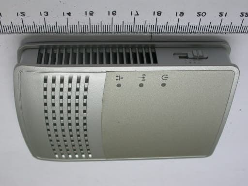
Click to zoom
Application Details
- Equipment Class
- DTS - Digital Transmission System
- Date of Grant
- Aug 15, 2004
- Application Purpose
- Original Equipment
- Date of Application
- Aug 15, 2004
- Equipment Note
- 3 in 1 AP
- Frequency Range
- 2412.00000000 - 2462.00000000
- Company
- Sercomm Corporation
- Country
- Taiwan
Documents & Files
Document Text
Text extracted from the exhibit documents filed with the FCC. Open a document above to read the original.
Users Manual
May 2004 (202-10034-01) 202-10034-01 Version 1.4 May 2004 Reference Manual for the 3 in 1 AP of IP802SM DECLARATION OF CON”FORMITY Per FCC Part 15 Section 15.19(a) (3) Responsible Party Name: SerComm Corporation Address: 46480 Woodview Common Fremont, CA 94539 U.S.A. Phone/Fax No: +1-510-870-1517 / +1 -510-661-9249 Hereby declares that the product Product Name: 3 in 1 AP Model Number: IP802SM ii May 2004 (202-10034-01) © 2004 by SerComm Corp. All rights reserved. Trademarks SerComm is a trademark of SerComm Corp. Microsoft, Windows, and Windows NT are registered trademarks of Microsoft Corporation. Other brand and product names are registered trademarks or trademarks of their respective holders. Statement of Conditions In the interest of improving internal design, operational function, and/or reliability, SerComm reserves the right to make changes to the products described in this document without notice. SerComm does not assume any liability that may occur due to the use or application of the product(s) or circuit layout(s) described herein. Certificate of the Manufacturer/Importer It is hereby certified that the 3 in 1 AP IP802SM has been suppressed in accordance with the conditions set out in the BMPT-AmtsblVfg 243/1991 and Vfg 46/1992. The operation of some equipment (for example, test transmitters) in accordance with the regulations may, however, be subject to certain restrictions. Please refer to the notes in the operating instructions. Federal Office for Telecommunications Approvals has been notified of the placing of this equipment on the market and has been granted the right to test the series for compliance with the regulations. Voluntary Control Council for Interference (VCCI) Statement This equipment is in the second category (information equipment to be used in a residential area or an adjacent area thereto) and conforms to the standards set by the Voluntary Control Council for Interference by Data Processing Equipment and Electronic Office Machines aimed at preventing radio interference in such residential areas. When used near a radio or TV receiver, it may become the cause of radio interference. Read instructions for correct handling. Customer Support Refer to the Support Information Card that shipped with your 3 in 1 AP IP802SM. World Wide Web SerComm maintains a World Wide Web home page that you can access at the universal resource locator (URL) http://www.sercomm.com. A direct connection to the Internet and a web browser such as Internet Explorer or Netscape are required. May 2004 (202-10034-01) EN 55 022 Declaration of Conformance This is to certify that the 54 Mbps Wireless Travel Router WGR101 is shielded against the generation of radio interference in accordance with the application of Council Directive 89/336/EEC, Article 4a. Conformity is declared by the application of EN 55 022 Class B (CISPR 22). Compliance with the applicable regulations is dependent upon the use of shielded cables. It is the responsibility of the user to procure the appropriate cables. Countries of Operation and Conditions of Use in the European Community This device is intended to be operated in all countries of the European Community. Requirements for indoor vs. outdoor operation, license requirements and allowed channels of operation apply in some countries as described below. NOTE:The user must use the configuration utility provided with this product to ensure the channels of operation are in conformance with the spectrum usage rules for European Community countries as described below. •This device requires that the user or installer properly enter the current country of operation in the Radio Configuration Window as described in the user guide, before operating this device. •This device will automatically limit the allowable channels of operation applicable to each country. Incorrectly entering the country of operation may result in illegal operation and may cause harmful interference to other system. The user is obligated to ensure the device is operating according to the channel limitations, indoor/outdoor restrictions and license requirements for each European Community country as described in this document. •This device may be operated indoors or outdoors in all countries of the European Community using the 2.4GHz band except where noted below. •In Italy the end-user must apply for a license from the national spectrum authority to operate this device outdoors. •In France outdoor operation is only permitted using the 2.4 – 2.454 GHz band: Channels 1 – 7. Federal Communications Commission (FCC) Compliance Notice: Radio Frequency Notice This equipment has been tested and found to comply with the limits for a Class B digital device, pursuant to part 15 of the FCC Rules. These limits are designed to provide reasonable protection against harmful interference in a residential installation. This equipment generates, uses, and can radiate radio frequency energy and, if not installed and used in accordance with the instructions, may cause harmful interference to radio communications. However, there is no guarantee that interference will not occur in a particular installation. If this equipment does cause harmful interference to radio or television reception, which can be determined by turning the equipment off and on, the user is encouraged to try to correct the interference by one or more of the following measures: •Reorient or relocate the receiving antenna. •Increase the separation between the equipment and receiver. •Connect the equipment into an outlet on a circuit different from that to which the receiver is connected. •Consult the dealer or an experienced radio/TV technician for help. FCC Caution 1.FCC RF Radiation Exposure Statement: The equipment complies with FCC RF radiation exposure limits set forth for an uncontrolled environment. This equipment should be installed and operated with a minimum distance of 20 centimeters between the radiator and your body. 2.This Transmitter must no…
Text truncated - open the document above for the full version.
Users Manual
About This Manual1 May 2004 (202-10034-01) Chapter 1 About This Manual This chapter describes the intended audience, scope, conventions, and formats of this manual. Audience, Scope, Conventions, and Formats This reference manual assumes that the reader has basic to intermediate computer and Internet skills. However, basic computer network, Internet, firewall, and VPN technologies tutorial information is provided in the Appendices and on the Netgear website. This guide uses the following typographical conventions: This guide uses the following formats to highlight special messages: This manual is written for the WGR101 wireless travel router according to these specifications.: Table 1-1.Typographical Conventions italicsEmphasis, books, CDs, URL names bold times romanUser input courier fontScreen text, file and server names, extensions, commands, IP addresses Note: This format is used to highlight information of importance or special interest. Table 1-2.Manual Scope Product Version54 Mbps Wireless Travel Router WGR101 Manual Publication DateMay 2004 Note: Product updates are available on the NETGEAR Web site at www.netgear.com/support/main.asp. Reference Manual for the 54 Mbps Wireless Travel Router WGR101 2About This Manual May 2004 (202-10034-01) How to Use This Manual The HTML version of this manual includes a variety of navigation features as well as links to PDF versions of the full manual and individual chapters. Figure 1 -1: HTML version of this manual 1. Left pane. Use the left pane to view the Contents, Index, Search, and Favorites tabs. To view the HTML version of the manual, you must have a version 4 or later browser with JavaScript enabled. 2. Toolbar buttons. Use the toolbar buttons across the top to navigate, print pages, and more. The Show in Contents button locates the current topic in the Contents tab. Previous/Next buttons display the previous or next topic. The PDF button links to a PDF version of the full manual. The Print button prints the current topic. Click this button when a step-by-step procedure is displayed to send the entire procedure to your printer. You do not have to worry about specifying the correct range of pages. 3. Right pane. Use the right pane to view the contents of the manual. Also, each page of the manual includes a link at the top right which links to a PDF file containing just the currently selected chapter of the manual. 1 2 3 Reference Manual for the 54 Mbps Wireless Travel Router WGR101 About This Manual3 May 2004 (202-10034-01) How to Print this Manual To print this manual you can choose one of the following several options, according to your needs. •Printing a “How To” Sequence of Steps in the HTML View. Use the Print button on the upper right of the toolbar to print the currently displayed topic. Use this button when a step-by-step procedure is displayed to send the entire procedure to your printer. You do not have to worry about specifying the correct range of pages. •Printing a Chapter. Use the link at the top right of any page. –Click “PDF of This Chapter” link at the top right of any page in the chapter you want to print. The PDF version of the chapter you were viewing opens in a browser window. Note: Your computer must have the free Adobe Acrobat reader installed in order to view and print PDF files. The Acrobat reader is available on the Adobe web site at http://www.adobe.com. –Click the print icon in the upper left of the window. Tip: If your printer supports printing two pages on a single sheet of paper, you can save paper and printer ink by selecting this feature. •Printing the Full Manual. Use the PDF button in the toolbar at the top right of the browser window. –Click the PDF button on the upper right of the toolbar. The PDF version of the chapter you were viewing opens in a browser window. –Click the print icon in the upper left of the window. Tip: If your printer supports printing two pages on a single sheet of paper, you can save paper and printer ink by selecting this feature. Reference Manual for the 54 Mbps Wireless Travel Router WGR101 4About This Manual May 2004 (202-10034-01) Introduction2-1 May 2004 (202-10034-01) Chapter 2 Introduction Congratulations on your purchase of the NETGEAR ® 54 Mbps Wireless Travel Router WGR101 . The WGR101 wireless travel router provides connection for multiple computers to the Internet through an RJ45 wall slot or an external broadband access device (such as a cable modem) that is normally intended for use by a single computer. This chapter describes the features of the NETGEAR 54 Mbps Wireless Travel Router WGR101 . Key Features The 54 Mbps Wireless Travel Router WGR101 with 4-port switch connects one or more wireless computers to the Internet through an RJ45 slot, router, or cable modem. With minimum setup, you can install and use the router within minutes. The WGR101 wireless travel router provides the following features: •802.11g wireless networking, with the ability to operate in 802.11g-only, or 802.11b+g modes. •Easy, web-based setup for installation and management. •Ethernet connection to an RJ45 wall slot, router, or cable modem. •Extensive Protocol Support. •Login capability. •Front panel LEDs for easy monitoring of status and activity. •Flash memory for firmware upgrade. Note: This manual provides information on the complete features as of the date of publication. Earlier versions of this product may not have all the features presented in this manual. Check the NETGEAR Web site at www.netgear.com/support/main.asp where you will find product firmware updates for your WGR101. Reference Manual for the 54 Mbps Wireless Travel Router WGR101 2-2Introduction May 2004 (202-10034-01) 802.11g Wireless Networking The WGR101 wireless travel router includes an 802.11g wireless access point, providing continuous, high-speed 54 Mbps access between your wireless and Ethernet devices. The access point provides: •802.11g wireless networking at up to 54 Mbps. •802.11g wireless networking, with the…
Text truncated - open the document above for the full version.
Cover Letter(s)
SerComm Corp. 8F, No. 3-1, YuanQu St., NanKang, Taipei 115, Taiwan, R.O.C Federal Communications Commission Dear Sir, We, the undersigned, hereby authorize Exclusive Certification Corp. to act on our behalf in all matters relating to application for 3 in 1 AP (Model: IP802SM, FCC ID No.: P27IP802SM)” authorization, including the signing of all documents relating to these matters. Any and all carried out by Exclusive Certification Corp. on our behalf shall have the same effect as acts of our own. The applicant certifies that in the case of an individual applicant (e.g., corporation), no party to the applicant is subject to a denial of federal benefits, that includes FCC benefits, pursuant to section 5301 of the Anti-drug abuse Act of 1988.21 U.S.A. 862. For a definition of a “party” for these purposes See 47 C.F.R. 1.2002(b). Applicant: SerComm Corp. Address: 8F, No.3-1, YuanQu St., NanKang, Taipei 115, Taiwan, R.O.C Tel: +886-2-2655-3988 Fax: +886-2-2655-3765 E-mail: [email protected] Date: July 29, 2004
Cover Letter(s)
American Telecommunications Certification Body Inc. 6731 Whittier Ave, McLean, VA 22101 August 3, 2004 RE: SerComm Corp. FCC ID: P27IP802SM or PY3IP802SM After a review of the submitted information, I have a few comments on the above referenced Application. 1) The application was uploaded as FCC ID: P27IP802SM, but the 731 form states PY3IP802SM. Please correct the 731 for the correct FCC ID. 2) The sample label provided is blank. Please correct to include all the appropriate FCC information (FCC ID, 2 part FCC statement, and DoC information is applicable). 3) Please confirm that a DoC has been performed for this device using an accredited test lab and the minimum test configuration per ANSI C63.4. 4) Please clarify if you are asking for: a) Certification of the device as a TX, and a DoC has been performed by an appropriately accredited test lab for a PC peripheral b) Certification as a TX + PC peripheral. Note 1: The option b) would be considered as a composite application and 2 certificates (one for the TX, one for the PC peripheral portion) would be issued. There are additional review costs associated with this additional certification. Note 2: to qualify to perform DoC applications, the test lab must be accredited (i.e. NVLAP or A2LA) to perform testing under the DoC procedure. ECC does not appear as an accredited test lab on the FCC site. Please explain. Note 3: Note that for DoC tests, the device is configured with a minimum test configuration as specified by ANSI C63.4 which includes complete computer + 2 I/O devices attached (one may be the EUT). Note 4: For the remaining part of this review, it is assumed that the device is being approved under a DoC for the PC peripheral portion. 5) Note that the label could not be verified. If the device is DoC approved, then the label should include the appropriate information for this as well. --- Continued on Next Page --- z Page 2 August 3, 2004 6) If the device is also been approved using a DoC, then the users manual must include the following on a single page: COMPLIANCE INFORMATION FOR DoC AUTHORIZATIONS (47CFR 2.1077) If a product is tested and authorized under a Declaration of Conformity, a compliance information statement shall be supplied with the product at the time of marketing or importation, containing the following information on a single page: (1) Identification of the product, i.e. name and model number. (2) A statement similar to that contained in Section 15.19(a)(3) that the product complies with Part 15 of the regulations. (3) The identification, by name, address and telephone number, of the responsible party. The responsible party is defined as either the manufacturer, or if the equipment is imported, the importer. The responsible party for a Declaration of Conformity must be located within the United States. Timothy R. Johnson Examining Engineer mailto: [email protected] The items indicated above must be submitted before processing can continue on the above referenced application. Failure to provide the requested information may result in application termination. Correspondence should be considered part of the permanent submission and may be viewed from the Internet after a Grant of Equipment Authorization is issued. Please do not respond to this correspondence using the email reply button. In order for your response to be processed expeditiously, you must submit your documents through the AmericanTCB.com website. Also, please note that partial responses increase processing time and should not be submitted. Any questions about the content of this correspondence should be directed to the sender.
Cover Letter(s)
Hi Timothy The DoC report of this device has been performed by an accredited test lab. and tested configuration per ANSI C63.4. We just only asking for certification of the device as a TX. Thank you. 陳以菡 Ivy Chen 廣駒科技股份有限公司 Exclusive Certification Corporation
Cover Letter(s)
American Telecommunications Certification Body Inc. 6731 Whittier Ave, McLean, VA 22101 August 16, 2004 RE: SerComm Corp. FCC ID: P27IP802SM After a review of the submitted information, I have a few comments on the above referenced Application. 1) FYI.....The DoC information should include the statements from Section 15.19(a)(3), not simply a reference to this paragraph. Please be sure the manufacturer corrects this. Timothy R. Johnson Examining Engineer mailto: [email protected] The items indicated above must be submitted before processing can continue on the above referenced application. Failure to provide the requested information may result in application termination. Correspondence should be considered part of the permanent submission and may be viewed from the Internet after a Grant of Equipment Authorization is issued. Please do not respond to this correspondence using the email reply button. In order for your response to be processed expeditiously, you must submit your documents through the AmericanTCB.com website. Also, please note that partial responses increase processing time and should not be submitted. Any questions about the content of this correspondence should be directed to the sender.
Cover Letter(s)
SerComm Corp. July 29, 2004 Federal Communications Commission Authorization and Evaluation Division FCC IDP27IP802SM Confidentiality Request Pursuant to Sections 0.457 and 0.459 of the Commission’s Rules, the Applicant Hereby requests confidential treatment of information accompaniment this Application As outlined below: 1. Block Diagram, 2. Schematic Diagram, The above materials contain trade secrets and proprietary information not customarily released to the public. The public disclosure of these matters might be harmful to the Applicant and provide unjustified benefits to its competitors. The Applicant understands that pursuant to Rule 0.457, disclosure of this Application and all accompanying documentation will not be made before the date of the Grant for this application Address: 8F, No. 3-1, YuanQu St., NanKang, Taipei 115, Taiwan, R.O.C TEL: +886-2-2655-3988 FAX: +886-2-2655-3765 3. Operational Principle
ID Label/Location Info
0560 ! IP802SM SerComm Corp. Size: 37*56.5mm FCC ID: P27IP802SM
RF Exposure Info
1.1. Test Result of RF Exposure Evaluation . Product: Wireless Router . Test Item: RF Exposure Evaluation Data . Test site: OATSI-SD . Test Mode: Normal Operation 1.1.1. Antenna Gain The maximum Gain is 1.0 dBi. 1.1.2. EUT Operation condition Software provided by client enabled the EUT to transmit and receive data at lowest, middle and highest channel individually. 1.1.3. Output Power into Antenna & RF Exposure Evaluation Distance Modulation Standard: IEEE 802.11b Test Date: May. 18, 2004 Temperature: 25 Humidity: 58 Channel Channel Frequency (MHz) Output Power to Antenna (dBm) Power Density (S) (mW/cm 2 ) 01 2412 14.85 0.0077 06 2437 12.36 0.0043 11 2462 11.62 0.0036 Modulation Standard: IEEE 802.11g Test Date: May. 18, 2004 Temperature: 25 Humidity: 58 Channel Channel Frequency (MHz) Output Power to Antenna (dBm) Power Density (S) (mW/cm 2 ) 01 2412 10.29 0.0027 06 2437 10.28 0.0027 11 2462 10.04 0.0025 The MPE is calculated as 0.0077 mW / cm 2 < limit 1 mW / cm 2 . So, RF exposure limit warning or SAR test are not required.
Test Report
Exclusive Certification Corp. Tel:886-2-2792-3366 Fax:886-2-2792-1100 Issued date: Jul. 07, 2004 1 of 74 FCC ID: P27IP802SM FCC Test Report: FI04051202-B FCC TEST REPORT according to FCC Rules and Regulations Part 15 Subpart C Applicant SerComm Corporation Address 8F, No. 3-1, YuanQu St., NanKang, Taipei 115, Taiwan, R.O.C. Equipment 3 in 1 AP Model No. IP802SM FCC ID P27IP802SM Trade Name SerComm † The test result refers exclusively to the test presented test model / sample. † Without written approval of Exclusive Certification Corp. the test report shall not be reproduced except in full. Exclusive Certification Corp. Tel:886-2-2792-3366 Fax:886-2-2792-1100 Issued date: Jul. 07, 2004 2 of 74 FCC ID: P27IP802SM FCC Test Report: FI04051202-B Contents 1. Report of Measurements and Examinations..................................................................................4 1.1. List of Measurements and Examinations.............................................................................4 1.2. Antenna Requirements......................................................................................................5 1.3. Test of Conducted Emission...............................................................................................6 1.4. Test of Radiated Emission.................................................................................................8 1.5. 6dB Bandwidth.................................................................................................................9 1.6. Maximum Peak Output Power............................................................................................9 1.7. Band Edges Measurement..............................................................................................10 1.8. Power Spectral Density...................................................................................................10 1.9. Restricted Bands of Operation.........................................................................................11 1.10. Labeling Requirement.....................................................................................................11 1.11. RF Exposure..................................................................................................................12 2. Test Configuration of Equipment under Test................................................................................14 2.1. Test Mode and Test Software...........................................................................................14 2.2. Description of Test System..............................................................................................14 2.3. Connection Diagram of Test System.................................................................................15 2.4. Feature of Equipment under Test.....................................................................................15 2.5. History of this test report..................................................................................................15 3. General Information of Test........................................................................................................16 4. Test Result and Data.................................................................................................................17 4.1. Antenna Requirement.....................................................................................................17 4.2. Test Result of Conducted Emission..................................................................................18 4.3. RF Portion......................................................................................................................33 4.4. 6dB Bandwidth Measurement Data..................................................................................49 4.5. Peak Output Power Measurement Data............................................................................53 4.6. Band Edges Measurement Data......................................................................................57 4.7. Power Spectral Density Measurement Data......................................................................69 4.8. Test Result of RF Exposure Evaluation.............................................................................73 5. List of Measuring Equipment Used.............................................................................................74 Appendix A. Photographs of EUT........................................................................ .............A1 ~ A7 Exclusive Certification Corp. Tel:886-2-2792-3366 Fax:886-2-2792-1100 Issued date: Jul. 07, 2004 3 of 74 FCC ID: P27IP802SM FCC Test Report: FI04051202-B CERTIFICATE OF COMPLIANCE according to FCC Rules and Regulations Part 15 Subpart C Applicant SerComm Corporation Address 8F, No. 3-1, YuanQu St., NanKang, Taipei 115, Taiwan, R.O.C. Equipment 3 in 1 AP Model No. IP802SM FCC ID P27IP802SM I HEREBY CERTIFY THAT : The measurements shown in this test report were made in accordance with the procedures given in ANSI C63.4. The equipment was passed the test performed according to FCC Rules and Regulations Part 15 Subpart C (2002). The test was carried out on May. 24, 2004 at Exclusive Certification Corp. Signature Anson Chou / Manager Exclusive Certification Corp. Tel:886-2-2792-3366 Fax:886-2-2792-1100 Issued date: Jul. 07, 2004 4 of 74 FCC ID: P27IP802SM FCC Test Report: FI04051202-B 1. Report of Measurements and Examinations 1.1. List of Measurements and Examinations FCC Rule . Description of Test Result 15.203 . Antenna Requirement Pass 15.207 . Conducted Emission Pass 15.209 . Radiated Emission Pass 15.247(a)(2) . 6dB Bandwidth Pass 15.247(b) . Maximum Peak Output Power Pass 15.247(c) . 100kHz Bandwidth of Frequency Band Edges Pass 15.247(d) . Power Spectral Density Pass 1.1307 1.1310 2.1091 2.1093 . RF Exposure Compliance Pass Test by: Exclusive Certification Corp. Tel:886-2-2792-3366 Fax:886-2-2792-1100 Is…
Text truncated - open the document above for the full version.
Test Report
Exclusive Certification Corp. Tel:886-2-2792-3366 Fax:886-2-2792-1100 Issued date: Jul. 07, 2004 29 of 74 FCC ID: P27IP802SM FCC Test Report: FI04051202-B Exclusive Certification Corp. Tel:886-2-2792-3366 Fax:886-2-2792-1100 Issued date: Jul. 07, 2004 30 of 74 FCC ID: P27IP802SM FCC Test Report: FI04051202-B Exclusive Certification Corp. Tel:886-2-2792-3366 Fax:886-2-2792-1100 Issued date: Jul. 07, 2004 31 of 74 FCC ID: P27IP802SM FCC Test Report: FI04051202-B Test by: Exclusive Certification Corp. Tel:886-2-2792-3366 Fax:886-2-2792-1100 Issued date: Jul. 07, 2004 32 of 74 FCC ID: P27IP802SM FCC Test Report: FI04051202-B 4.2.1. Photographs of Conducted Emission Test FRONT VIEW REAR VIEW Exclusive Certification Corp. Tel:886-2-2792-3366 Fax:886-2-2792-1100 Issued date: Jul. 07, 2004 33 of 74 FCC ID: P27IP802SM FCC Test Report: FI04051202-B 4.3. RF Portion 4.3.1. Test Result of Conducted Emission Exclusive Certification Corp. Tel:886-2-2792-3366 Fax:886-2-2792-1100 Issued date: Jul. 07, 2004 34 of 74 FCC ID: P27IP802SM FCC Test Report: FI04051202-B Exclusive Certification Corp. Tel:886-2-2792-3366 Fax:886-2-2792-1100 Issued date: Jul. 07, 2004 35 of 74 FCC ID: P27IP802SM FCC Test Report: FI04051202-B Exclusive Certification Corp. Tel:886-2-2792-3366 Fax:886-2-2792-1100 Issued date: Jul. 07, 2004 36 of 74 FCC ID: P27IP802SM FCC Test Report: FI04051202-B 4.3.2. Test Result of Radiated Emission Exclusive Certification Corp. Tel:886-2-2792-3366 Fax:886-2-2792-1100 Issued date: Jul. 07, 2004 37 of 74 FCC ID: P27IP802SM FCC Test Report: FI04051202-B Exclusive Certification Corp. Tel:886-2-2792-3366 Fax:886-2-2792-1100 Issued date: Jul. 07, 2004 38 of 74 FCC ID: P27IP802SM FCC Test Report: FI04051202-B Exclusive Certification Corp. Tel:886-2-2792-3366 Fax:886-2-2792-1100 Issued date: Jul. 07, 2004 39 of 74 FCC ID: P27IP802SM FCC Test Report: FI04051202-B Test by: Exclusive Certification Corp. Tel:886-2-2792-3366 Fax:886-2-2792-1100 Issued date: Jul. 07, 2004 40 of 74 FCC ID: P27IP802SM FCC Test Report: FI04051202-B Modulation Standard: IEEE 802.11b a) Emission frequencies below 1 GHz Test Date: May. 24, 2004 Temperature: 25 Humidity: 59 Frequency (MHz) Ant-Pol H/V Meter Reading (dBuV) Corrected Factor (dB) Result@3m (dBuV/m) Limit@3m (dBuV/m) Margin (dB) Table Deg. Ant High (m) 924.40 H 36.36 3.66 40.02 46.0 -5.98 180 1.5 37.29 V 48.70 -13.11 35.59 40.0 -4.41 180 1.5 39.99 V 52.23 -14.46 37.77 40.0 -2.23 180 1.5 126.93 V 54.84 -15.61 39.23 43.5 -4.27 180 1.5 132.33 V 55.45 -15.54 39.91 43.5 -3.59 180 1.5 481.30 V 51.48 -6.54 44.94 46.0 -1.06 180 1.5 642.30 V 45.26 -2.08 43.18 46.0 -2.82 180 1.5 Notes: 1. Result = Meter Reading + Corrected Factor 2. Corrected Factor = Antenna Factor + Cable Loss – Amplifier b) Emission frequencies above 1 GHz Radiated emission frequencies above 1 GHz to 25 GHz were too low to be measured. Exclusive Certification Corp. Tel:886-2-2792-3366 Fax:886-2-2792-1100 Issued date: Jul. 07, 2004 41 of 74 FCC ID: P27IP802SM FCC Test Report: FI04051202-B Modulation Standard: IEEE 802.11g a) Emission frequencies below 1 GHz Test Date: May. 24, 2004 Temperature: 25 Humidity: 59 Frequency (MHz) Ant-Pol H/V Meter Reading (dBuV) Corrected Factor (dB) Result@3m (dBuV/m) Limit@3m (dBuV/m) Margin (dB) Table Deg. Ant High (m) 481.30 H 47.73 -6.53 41.20 46.0 -4.81 180 1.5 640.90 H 41.04 -2.09 38.95 46.0 -7.05 180 1.5 924.40 H 37.70 3.66 41.36 46.0 -4.64 180 1.5 39.99 V 52.58 -14.46 38.12 40.0 -1.88 180 1.5 112.08 V 56.34 -16.31 40.03 43.5 -3.47 180 1.5 126.93 V 56.05 -15.61 40.44 43.5 -3.06 180 1.5 132.33 V 55.45 -15.54 39.91 43.5 -3.59 180 1.5 160.68 V 59.13 -17.06 42.07 43.5 -1.43 180 1.5 Notes: 1. Result = Meter Reading + Corrected Factor 2. Corrected Factor = Antenna Factor + Cable Loss - Amplifier b) Emission frequencies above 1 GHz Radiated emissio…
Text truncated - open the document above for the full version.
Contact Information
Applicant
Nick Wu(Engineer)
Technical Contact
Exclusive Certification Corp.Ivy Chen
[email protected]+886-2-2792-3366
4F-2, No.28, Lane 78, Xing-Ai Road · Taipei City · Taiwan
Non-Technical Contact
SerComm CorporationKevin Tzeng
[email protected]+886-2-2655-3988
Test Firm
Cerpass Technology CorporationAnson Chou
Technical Specifications
| # | Rule Parts | Frequency Range | Power Output |
|---|---|---|---|
| 1 | 15C | 2.41 GHz - 2.46 GHz | 31.00 mW |
Other Applications from Sercomm Corporation
P27-MOTIONZW60R0
Aug 04, 2026WIRELESS PIR MOTION SENSOR
Equipment Class
DTS - Digital Transmission SystemP27-SCP5173P
Dec 24, 2025Moso Canopy 5GOD2
Equipment Class
CBD - Citizens Band Category A and B DevicesP27-TPM530
Nov 24, 2025CATM1 Module
Equipment Class
PCB - PCS Licensed TransmitterP27MQIO
Sep 16, 2025Mqio 9W
Equipment Class
DTS - Digital Transmission SystemP27LORAAREAV2
Jul 25, 2024MachineQ Area 8C V2 LoRaWAN Gateway
Equipment Class
PCB - PCS Licensed Transmitter