P27IP806BBRCA WiFi Enabler
Sercomm Corporation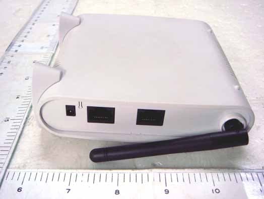
Click to zoom
Application Details
- Equipment Class
- DTS - Digital Transmission System
- Date of Grant
- Apr 01, 2008
- Application Purpose
- Original Equipment
- Date of Application
- Apr 01, 2008
- Equipment Note
- RCA WiFi Enabler
- Frequency Range
- 2412.00000000 - 2462.00000000
- Company
- Sercomm Corporation
- Country
- Taiwan
Documents & Files
Document Text
Text extracted from the exhibit documents filed with the FCC. Open a document above to read the original.
Users Manual
Quick Installation Guide 802.11g/802.11b Access Point/Router 1. Introduction Package Contents The following items should be included: If any of the above items are damaged or missing, please contact your dealer immediately. Physical Details Front Panel LEDs Power On - Normal operation. Off - No power LAN On - The LAN (Ethernet) port is active. Off - No active connection on the LAN (Ethernet) port. Flashing - Data is being transmitted or received via the corresponding LAN (Ethernet) port. WAN On - The WAN (Ethernet) port is active. Off - No active connection on the WAN (Ethernet) port. Flashing - Data is being transmitted or received via the corresponding WAN (Ethernet) port. Wireless LAN On - Idle. Off - Error- Wireless connection is not available. Flashing - Data is being transmitted or received via the Wireless access point. Data includes "network traffic" as well as user data. Mode On – AP mode Off – Router mode WPS Following WPS standard SPEC Rear Panel Antennae One antenna is supplied. Best results are usually obtained with the antennae in a vertical position. Reset Button This button has two (2) functions: Reboot. When pressed and released, the Wireless Access Point will reboot (restart). Reset to Factory Defaults. This button can also be used to clear ALL data and restore ALL settings to the factory default values, as follows: 1. Power off the Access Point. 2. Hold the Reset Button down while you Power On the Access Point. 3. Continue holding the Reset Button until the Status (Red) LED blinks TWICE. 4. Release the Reset Button. The factory default configuration has now been restored, and the Access Point is ready for use. WPS Button The button is for WPS function: After pressed and released, router enter into mode which can support WPS client to connect Ethernet LAN Use a standard LAN cable (RJ45 connectors) to connect this port to a 10BaseT or 100BaseT hub on your LAN. Ethernet WAN Use a standard LAN cable (RJ45 connectors) to connect this port. In AP mode, connect this port to a 10BaseT or 100BaseT hub on your LAN. In Router mode, connect this port to a DSL modem Power port Connect the supplied power adapter here. 2. Installation 1. Select a suitable location for the installation of your Wireless Access Point. To maximize reliability and performance, follow these guidelines: • Use an elevated location, such as wall mounted or on the top of a cubicle. • Place the Wireless Access Point near the center of your wireless coverage area. • If possible, ensure there are no thick walls or metal shielding between the Wireless Access Point and Wireless stations. 2. Use a standard LAN cable to connect the “LAN” port on the Wireless Access Point to a 10/100BaseT hub on your LAN. 3. If used as router, use a standard LAN cable to connect the “Wan” port on the Wireless Access Point to DSL modem. 4. Connect the supplied power adapter to the Wireless Access Point and a convenient power outlet, and power up. 5. Check the LEDs: • The Power, Wireless LAN, and LAN LEDs should be ON. 3. Access Point Setup The default settings are: • SSID: Thomson • WPA-PSK: Enabled • Key: Generate from MAC address If you need to change these, follow this procedure. 1. Check the Wireless Access Point to determine its Default Name. This is shown on a label on the base or rear, and is in the following format: SCxxxxxx Where xxxxxx is a set of 6 Hex characters ( 0 ~ 9, and A ~ F ). 2. Use a PC which is already connected to your LAN, either by a wired connection or another Access Point. • Until the Wireless Access Point is configured, establishing a Wireless connection to it may be not possible. • If your LAN contains a Router or Routers, ensure the PC used for configuration is on the same LAN segment as the Wireless Access Point. 3. Start your Web browser. 4. For the Address enter "HTTP://" and the Default IP of the Wireless Access Point e.g. HTTP://192.168.0.1 5. You should then see a login prompt, which will ask for a User Name and Password. Enter admin for the User Name, and leave the Password blank. These are the default values. If they are changed, use the current values. 6. You will then see the Status screen, which displays the current settings and status. No data input is possible on this screen. 7. From the menu, select and configure the following options, using the on-line help if necessary. 8. Setup of the Wireless Access Point is now complete. Note: The CD-ROM contains a Windows utility which can be used to assist setup. 4. Client (PC) Configuration WEP/WPA-PSK Mode Each Wireless Station must have the same settings as the Wireless Access Point. Mode On each PC, the mode must be set to Infrastructure. SSID (ESSID) This must match the value used on the Wireless Access Point. The default value is default Note! The SSID is case sensitive. WEP WPA-PSK If WEP or WPA-PSK is enabled on the Wireless Access Point, each station must use the same settings as the Wireless Access Point. Regulatory Approvals FCC Statement This equipment has been tested and found to comply with the limits for a Class B digital device, pursuant to Part 15 of the FCC Rules. These limits are designed to provide reasonable protection against harmful interference in a residential installation. This equipment generates, uses and can radiate radio frequency energy and, if not installed and used in accordance with the instructions, may cause harmful interference to radio communica- tions. However, there is no guarantee that interference will not occur in a particular installation. If this equipment does cause harmful interference to radio or television reception, which can be determined by turning the equipment off and on, the user is encouraged to try to correct the interference by one of the following measures: Reorient or relocate the receiving antenna. Increase the separation between the equipment and receiver. Connect the equipment into an outlet on a circuit different from that to which the receiver is connected. Consult the dealer or an experi…
Text truncated - open the document above for the full version.
Cover Letter(s)
Request for non-disclosure RF_501_02 SerComm Corporation 8F, No.3-1, YuanQu St., NanKang Taipei Taiwan, R.O.C. To: Telefication B.V. Attn: Dept. FCC TCB Edisonstraat 12A 6902 PK ZEVENAAR The Netherlands Subject: Request for non-disclosure (FCC ID:P27IP806BB) Reference number: IP806BB Date: 2008/03/25 Dear FCC TCB, Persuant to 47 CFR Section 0.459(a) & (b), SerComm Corporation hereby requests non-disclosure and confidential treatment of the following materials submitted in support of FCC certification application for FCC ID: ( P27IP806BB) a. Schematic diagrams b. Operational description c. Block Diagram Above materials contain secrets, proprietary and technical information, which would customarily be quarded from competitors under 47 CFR, section 0.457(d)(2). Disclosure or publication or any portion of this company confidential material to other parties could cause substantial competitive harm and provide unjustified benefits for competitors. SerComm Corporation understands that pursuant to 47 CFR section 0.457(d)(1)(ii) disclosure of the applicant and all accompanying documentation will not be made before the date of the grant. Ronnie Cheng/ Associate Manager/ R&D Division Signature:
Cover Letter(s)
RF_160, Issue 02 Declaration of Authorization We Name: SerComm Corporation Address: 8F, No.3-1, YuanQu St., NanKang, City: Taipei Country: Taiwan, R.O.C. Declare that: Name Representative of agent: Delia Feng. (1) Agent Company name: Exclusive Certification Corporation Address: 4F-2, No.28 Lang 78, Xing-Ai Rd. City: Nei-hu Taipei City 114 Country Taiwan, R.O.C. is authorized to apply for Certification of the following product(s): Product description: RCA WiFi Enabler Type designation: IP806BB Trademark: Audio Vox on our behalf. Date: 2008/03/25 City: Taipei Name: Ronnie Cheng (2) Function: Associate Manager/ R&D Division Signature: Notes: (1): Required for FCC application (2): For FCC it must be the Grantee Code “owner” or the authorized agent.
External Photos
Exclusive Certification Corp. Tel:886-2-2792-3366 Fax:886-2-2792-1100 Issued date: Mar. 31, 2008 1 of 6 FCC Test Report: FI08031303-A Appendix A. Photographs of EUT 08031303-A 08031303-A
ID Label/Location Info
Label & Location
Internal Photos
Exclusive Certification Corp. Tel:886-2-2792-3366 Fax:886-2-2792-1100 Issued date: Mar. 31, 2008 2 of 6 FCC Test Report: FI08031303-A 08031303-A 08031303-A Exclusive Certification Corp. Tel:886-2-2792-3366 Fax:886-2-2792-1100 Issued date: Mar. 31, 2008 3 of 6 FCC Test Report: FI08031303-A 08031303-A 08031303-A Exclusive Certification Corp. Tel:886-2-2792-3366 Fax:886-2-2792-1100 Issued date: Mar. 31, 2008 4 of 6 FCC Test Report: FI08031303-A 08031303-A 08031303-A Exclusive Certification Corp. Tel:886-2-2792-3366 Fax:886-2-2792-1100 Issued date: Mar. 31, 2008 5 of 6 FCC Test Report: FI08031303-A 08031303-A Exclusive Certification Corp. Tel:886-2-2792-3366 Fax:886-2-2792-1100 Issued date: Mar. 31, 2008 6 of 6 FCC Test Report: FI08031303-A 08031303-A 08031303-A
Test Report
Exclusive Certification Corp. Tel:886-2-2792-3366 Fax:886-2-2792-1100 Issued date: Mar. 31, 2008 1 of 54 FCC Test Report: FI08031303-A FCC TEST REPORT according to FCC Rules and Regulations Part 15 Subpart C Applicant : SerComm Corporation Address : 8F, No. 3-1, YuanQu St., NanKang, Taipei 115, Taiwan, R.O.C. Equipment : RCA WiFi Enabler Model No. : IP806BB FCC ID : P27IP806BB Trade Name : AudioVox Laboratory Accreditation The test result refers exclusively to the test presented test model / sample., Without written approval of Exclusive Certification Corp. the test report shall not be reproduced except in full. The EUT is also considered as a kind of computer peripheral, because the connection to computer is necessary for typical use. It has been verified to comply with the requirements of FCC Part 15, Subpart B, Class B (DoC). The test report has been issued separately. Exclusive Certification Corp. Tel:886-2-2792-3366 Fax:886-2-2792-1100 Issued date: Mar. 31, 2008 2 of 54 FCC Test Report: FI08031303-A Contents 1. Report of Measurements and Examinations .................................................................................... 5 1.1 List of Measurements and Examinations ................................................................................... 5 2. Test Configuration of Equipment under Test ................................................................................... 6 2.1 Feature of Equipment under Test............................................................................................... 6 2.2 RF Specifications ....................................................................................................................... 6 2.3 Test Mode & Test Software ........................................................................................................ 7 2.4 Description of Test System......................................................................................................... 7 2.5 Connection Diagram of Test System.......................................................................................... 8 2.6 General Information of Test........................................................................................................ 9 2.7 Measurement Uncertainty .......................................................................................................... 9 2.8 History of this test report ..........................................................................................................10 3. Antenna Requirements..................................................................................................................... 11 3.1 Standard Applicable ................................................................................................................. 11 3.2 Antenna Construction and Directional Gain............................................................................. 11 4. Test of Conducted Emission............................................................................................................12 4.1 Test Limit .................................................................................................................................. 12 4.2 Test Procedures .......................................................................................................................12 4.3 Typical Test Setup ....................................................................................................................13 4.4 Measurement equipment ......................................................................................................... 13 4.5 Test Result and Data................................................................................................................14 4.6 Test Photographs .....................................................................................................................16 5. Test of Radiated Emission ...............................................................................................................17 5.1 Test Limit .................................................................................................................................. 17 5.2 Test Procedures .......................................................................................................................17 5.3 Typical Test Setup ....................................................................................................................18 5.4 Measurement equipment ......................................................................................................... 18 5.5 Test Result and Data................................................................................................................19 5.6 Test Photographs .....................................................................................................................35 6. 6dB Bandwidth Measurement Data .................................................................................................36 6.1 Test Limit .................................................................................................................................. 36 6.2 Test Procedures .......................................................................................................................36 6.3 Test Setup Layout ....................................................................................................................36 6.4 Measurement equipment ......................................................................................................... 36 6.5 Test Result and Data................................................................................................................36 7. Maximum Peak Output Power .........................................................................................................40 7.1 Test Limit ...............................................................................................…
Text truncated - open the document above for the full version.
Test Setup Photos
Exclusive Certification Corp. Tel:886-2-2792-3366 Fax:886-2-2792-1100 Issued date: Mar. 31, 2008 16 of 54 FCC Test Report: FI08031303-A 4.6 Test Photographs Front View Rear View Exclusive Certification Corp. Tel:886-2-2792-3366 Fax:886-2-2792-1100 Issued date: Mar. 31, 2008 35 of 54 FCC Test Report: FI08031303-A 5.6 Test Photographs Front View Rear View
Contact Information
Applicant
Nick Wu(Engineer)
Test Firm
Cerpass Technology CorporationAnson Chou
Technical Specifications
| # | Rule Parts | Frequency Range | Power Output |
|---|---|---|---|
| 1 | 15C | 2.41 GHz - 2.46 GHz | 86.00 mW |
Other Applications from Sercomm Corporation
P27-MOTIONZW60R0
Aug 04, 2026WIRELESS PIR MOTION SENSOR
Equipment Class
DTS - Digital Transmission SystemP27-SCP5173P
Dec 24, 2025Moso Canopy 5GOD2
Equipment Class
CBD - Citizens Band Category A and B DevicesP27-TPM530
Nov 24, 2025CATM1 Module
Equipment Class
PCB - PCS Licensed TransmitterP27MQIO
Sep 16, 2025Mqio 9W
Equipment Class
DTS - Digital Transmission SystemP27LORAAREAV2
Jul 25, 2024MachineQ Area 8C V2 LoRaWAN Gateway
Equipment Class
PCB - PCS Licensed Transmitter