P27IP906SMWLAN Router
Sercomm Corporation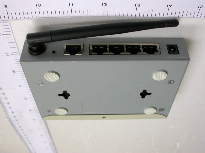
Click to zoom
Application Details
- Equipment Class
- DTS - Digital Transmission System
- Date of Grant
- Aug 25, 2005
- Application Purpose
- Original Equipment
- Date of Application
- Aug 25, 2005
- Equipment Note
- WLAN Router
- Frequency Range
- 5745.00000000 - 5825.00000000
- Company
- Sercomm Corporation
- Country
- Taiwan
Documents & Files
Document Text
Text extracted from the exhibit documents filed with the FCC. Open a document above to read the original.
Users Manual
A or G Wireless Router 802.11a/802.11g/802.11b Wireless Access Point Broadband Internet Access 4-Port Switching Hub User's Guide DECLARATION OF CONFORMITY Per FCC Part 2 Section 2.1077(a) Responsible Party Name: SerComm Corporation Address: 8F, No. 3-1, YuanQu St., NanKang, Taipei 115, Taiwan, R. O. C Phone / Fax No: +886-2-2655-3988 / +886-2-2655-3765 hereby declares that the product Product Name: A or G Wireless Router Model Number: IP906SM Comforms to the following specifications: FCC Part 15, Subpart B requlation. Representative Person's Name: _________________________ Signature: _________________________ Date: __________________________ Kevin Tsent Jul. 26, 2005 i Table of Contents CHAPTER 1 INTRODUCTION..............................................................................................................1 Wireless Router Features..............................................................................................................1 Package Contents.............................................................................................................................3 Physical Details................................................................................................................................5 CHAPTER 2 INSTALLATION...............................................................................................................7 Requirements....................................................................................................................................7 Procedure...........................................................................................................................................7 CHAPTER 3 SETUP..................................................................................................................................9 Overview.............................................................................................................................................9 Configuration Program.................................................................................................................11 Setup Wizard...................................................................................................................................13 LAN Screen.....................................................................................................................................16 Wireless Screen.............................................................................................................................18 Password Screen.............................................................................................................................23 CHAPTER 4 PC CONFIGURATION...................................................................................................24 Overview...........................................................................................................................................24 Windows Clients.............................................................................................................................24 Macintosh Clients...........................................................................................................................36 Linux Clients...................................................................................................................................36 Other Unix Systems.......................................................................................................................36 Wireless Station Configuration..................................................................................................37 CHAPTER 5 OPERATION AND STATUS.........................................................................................38 Operation..........................................................................................................................................38 Status Screen..................................................................................................................................38 Connection Status - PPPoE...........................................................................................................41 Connection Status - PPTP.............................................................................................................43 Connection Status - L2TP.............................................................................................................44 Connection Status - Telstra Big Pond........................................................................................45 Connection Details - SingTel RAS..............................................................................................47 Connection Details - Fixed/Dynamic IP Address......................................................................49 CHAPTER 6 ADVANCED FEATURES...............................................................................................51 Overview...........................................................................................................................................51 Access Control................................................................................................................................51 Dynamic DNS (Domain Name Server)........................................................................................56 Advanced Internet Screen.............................................................................................................58 URL Filter........................................................................................................................................62 Define Schedule..............................................................................................................................64 User Groups.....................................................................................................................................65 V…
Text truncated - open the document above for the full version.
Cover Letter(s)
American Telecommunications Certification Body Inc. 6731 Whittier Ave, McLean, VA 22101 July 21, 2005 RE: SerComm Corporation FCC ID: P27IP906SM After a review of the submitted information, I have a few comments on the above referenced Application. 1) The 731 form should be updated to list both DTS and NII equipment codes as the NII is applicable to the 5150 – 5350 band of operation. 2) The 731 form should list actual tunable frequencies for Part 15 devices, not simply ranges of operation. Please correct for the 5 GHz bands. 3) The 731 form states a low frequency of 5125 MHz. This is below the FCC allowed band of operation which starts at 5150 MHz. Please explain. 4) The users manual appears to show in the graphic section that you can select the region of the world (page 22). This is not allowed for devices shipped to the U.S as the end user is not allowed to have this freedom. Additionally the selectable channels may only be for channels approved for use in the U.S. Please explain how the device is compliant and adjust the manual as necessary. 5) The output power given on page 102 of the users manual is not consistent with the information presented in the application. The power information must be consistent throughout the application. Please review/correct as necessary. 6) Section 15.15(b) prohibits adjustments of any control by the user that will cause operation of a device in violation of the regulations. Accordingly, any proposal to allow the end user to choose extended channels on frequencies outside of an allowable frequency band in the USA is not acceptable. For example, a WLAN device operating according to Section 15.247 on channels 1-11 between 2.4 - 2.483.5 GHz must not have any user controls or software to allow the device to operate on channels 12 and 13 which are outside of the allowed USA band. For instance, the user should not be able to select alternative countries which would allow different channel plans outside of the allowed USA band. Please explain how this device is compliant to this requirement. 7) Test equipment for 5 GHz report section 5.4 does not appear to support measurements up to 40 GHz. For example, what amplifiers or other device were used in the range above 26.5 GHz. How was effective dynamic range achieved for higher frequency measurements (closer distances, etc.) Please review. 8) Information to the user regarding compliance to 15.407(e) could not be found in the users manual. Please adjust. 9) Information regarding compliance to 15.407(c) could not be located in the application. Please provide. 10) For 5 GHz peak power and PSD tests following the UNII procedure public notice (see attachment), it would be helpful to define which procedure was used for each of these measurements in the test report. It appears that method 3 was used to measure power. Which method was used for spectral density? If method 2, was power averaging (not video averaging) utilized? Please confirm. 11) Power spectral density results following UNII procedures appear over the FCC limits for all measurements made. Please review. Additionally, when reporting final measurements, please compare the results obtained to the limit. 12) Why does the power measurements between sections 6.3 and 12.3 differ for the high 5 GHz band. The method for UNII and DTS power measurement method 3 is the same (see attachments). Please review/explain/correct as necessary. z Page 2 July 21, 2005 13) FYI..... The users manual appears to be missing the following information as required for a DoC authorization. Please ensure this information get integrated into the users manual : COMPLIANCE INFORMATION FOR DoC AUTHORIZATIONS (47CFR 2.1077) If a product is tested and authorized under a Declaration of Conformity, a compliance information statement shall be supplied with the product at the time of marketing or importation, containing the following information on a single page : (1) Identification of the product, i.e. name and model number. (2) A statement similar to that contained in Section 15.19(a)(3) that the product complies with Part 15 of the regulations. (3) The identification, by name, address and telephone number, of the responsible party. The responsible party is defined as either the manufacturer, or if the equipment is imported, the importer. The responsible party for a Declaration of Conformity must be located within the United States. Timothy R. Johnson Examining Engineer mailto: [email protected] The items indicated above must be submitted before processing can continue on the above referenced application. Failure to provide the requested information may result in application termination. Correspondence should be considered part of the permanent submission and may be viewed from the Internet after a Grant of Equipment Authorization is issued. Please do not respond to this correspondence using the email reply button. In order for your response to be processed expeditiously, you must submit your documents through the AmericanTCB.com website. Also, please note that partial responses increase processing time and should not be submitted. Any questions about the content of this correspondence should be directed to the sender.
Cover Letter(s)
American Telecommunications Certification Body Inc. 6731 Whittier Ave, McLean, VA 22101 August 9, 2005 RE: SerComm Corporation FCC ID: P27IP906SM After a review of the submitted information, I have a few comments on the above referenced Application. 1) Section 15.15(b) prohibits adjustments of any control by the user that will cause operation of a device in violation of the regulations. Accordingly, any proposal to allow the end user to choose extended channels on frequencies outside of an allowable frequency band in the USA is not acceptable. For example, a WLAN device operating according to Section 15.247 on channels 1-11 between 2.4 - 2.483.5 GHz must not have any user controls or software to allow the device to operate on channels 12 and 13 which are outside of the allowed USA band. For instance, the user should not be able to select alternative countries which would allow different channel plans outside of the allowed USA band. Please explain how this device is compliant to this requirement. 2) Test equipment for 5 GHz report section 5.4 does not appear to support measurements up to 40 GHz. For example, what amplifiers or other device were used in the range above 26.5 GHz. How was effective dynamic range achieved for higher frequency measurements (closer distances, etc.). It appears that only the antenna and spectrum analyzer may have operated in the proper ranges, but given the gain of the antennas, how can proper dynamic range for measurements be achieved? Please review. 3) Information regarding compliance to 15.407(c) could not be located in the application. Please provide. 4) Why does the power measurements between sections 6.3 and 12.3 differ for the high 5 GHz band. The method for UNII and DTS power measurement method 3 is the same (see attachments). Please review/explain/correct as necessary. 5) FYI....The 731 form still does not list actual tunable frequencies for 5 GHz frequencies. Please correct this on future applications. Timothy R. Johnson Examining Engineer mailto: [email protected] The items indicated above must be submitted before processing can continue on the above referenced application. Failure to provide the requested information may result in application termination. Correspondence should be considered part of the permanent submission and may be viewed from the Internet after a Grant of Equipment Authorization is issued. Please do not respond to this correspondence using the email reply button. In order for your response to be processed expeditiously, you must submit your documents through the AmericanTCB.com website. Also, please note that partial responses increase processing time and should not be submitted. Any questions about the content of this correspondence should be directed to the sender.
Cover Letter(s)
American Telecommunications Certification Body Inc. 6731 Whittier Ave, McLean, VA 22101 August 15, 2005 RE: SerComm Corporation FCC ID: P27IP906SM After a review of the submitted information, I have a few comments on the above referenced Application. 1) Section 15.15(b) prohibits adjustments of any control by the user that will cause operation of a device in violation of the regulations. Accordingly, any proposal to allow the end user to choose extended channels on frequencies outside of an allowable frequency band in the USA is not acceptable. For example, a WLAN device operating according to Section 15.247 on channels 1-11 between 2.4 - 2.483.5 GHz must not have any user controls or software to allow the device to operate on channels 12 and 13 which are outside of the allowed USA band. For instance, the user should not be able to select alternative countries which would allow different channel plans outside of the allowed USA band. Please explain how this device is compliant to this requirement. 2) Information regarding compliance to 15.407(c) could not be located in the application. Please provide. Timothy R. Johnson Examining Engineer mailto: [email protected] The items indicated above must be submitted before processing can continue on the above referenced application. Failure to provide the requested information may result in application termination. Correspondence should be considered part of the permanent submission and may be viewed from the Internet after a Grant of Equipment Authorization is issued. Please do not respond to this correspondence using the email reply button. In order for your response to be processed expeditiously, you must submit your documents through the AmericanTCB.com website. Also, please note that partial responses increase processing time and should not be submitted. Any questions about the content of this correspondence should be directed to the sender.
Cover Letter(s)
American Telecommunications Certification Body Inc. 6731 Whittier Ave, McLean, VA 22101 August 22, 2005 RE: SerComm Corporation FCC ID: P27IP906SM After a review of the submitted information, I have a few comments on the above referenced Application. 1) For 15.15, we are asking for an explanation on how the device complies with the requirement as follows, not for changes to the users manual. Please provide an explanation on how the device complies with: Section 15.15(b) prohibits adjustments of any control by the user that will cause operation of a device in violation of the regulations. Accordingly, any proposal to allow the end user to choose extended channels on frequencies outside of an allowable frequency band in the USA is not acceptable. For example, a WLAN device operating according to Section 15.247 on channels 1-11 between 2.4 - 2.483.5 GHz must not have any user controls or software to allow the device to operate on channels 12 and 13 which are outside of the allowed USA band. For instance, the user should not be able to select alternative countries which would allow different channel plans outside of the allowed USA band. Timothy R. Johnson Examining Engineer mailto: [email protected] The items indicated above must be submitted before processing can continue on the above referenced application. Failure to provide the requested information may result in application termination. Correspondence should be considered part of the permanent submission and may be viewed from the Internet after a Grant of Equipment Authorization is issued. Please do not respond to this correspondence using the email reply button. In order for your response to be processed expeditiously, you must submit your documents through the AmericanTCB.com website. Also, please note that partial responses increase processing time and should not be submitted. Any questions about the content of this correspondence should be directed to the sender.
Cover Letter(s)
Dear Tim, I had uploaded some revised documents for IP906SM, please check. Thank you very much. Best Regards, Ivy
Cover Letter(s)
Dear Tim, About Comment No. 7, I just uploaded another revised test report to your website, please check. And about No. 9, could you please let me know what kind of statement or document should we provide? And No. 12, the two sections are also use the same method (3), but the VBW of section 6.3 is 300 KHz, and section 12.3 is 1 MHz, can it be down? Thank you very much. Best Regards, Ivy
Cover Letter(s)
Dear Tim, I just uploaded a updated users manual to your website, please check. And the data transmission is always initiated by software, which is then pass down through the MAC, through the digital and analog baseband, and finally to the RF chip. Several special packets (ACKs, CTS, PSPoll, etc...) are initiated by MAC. There are the only ways digital baseband portion will turn on the RF transmitter, which it then turns off at the end of the packet. Therefore, the transmitter will be on only while one of the aforementioned packets are being transmitted. Thank you very much. Best Regards, Ivy
Cover Letter(s)
Dear Tim, The users of this devise do not have any options to select countries other than the United States because channels 12 and 13 are disabled by software which is locked into firmware of this devise. Thank you very much. Best Regards, Ivy
External Photos
External Photos
ID Label/Location Info
FCC ID: P27IP906SM SerComm IP906SM A or G Wireless Router
Internal Photos
Internal Photos
Operational Description
Part Number970RX000F8 Date94/6/8 SubjectIP906SM pages2 IP906SM Operation Principle 1. CPU, U6, 88W8510H have a 32-bit RISC processor integrated, operation frequency is 132MHz. It needs an external 44MHz crystal for reference frequency; this crystal is also used for RF module. This chip is responsible to control RF-Baseband Transceiver (88W8030), Flash IC and LED. This chip also has MII interface integrated to communicate with 10/100 Ethernet Switch. 2. FLASH, U13, MX29LV800BTTC-70EC, 8Mbits Flash, bottom sector, 70ns. It is used to store the normal and test firmware. 3. Integrated 2.4GHz & 5GHz ISM Band RF-Baseband Transceiver, U1, 88W8030 is fully integrated RF to baseband transceiver that operation in both the 2.4GHz ISM radio band for 802.11g/b WLAN applications and the 5GHz UNII radio band for 802.11a WLAN applications. It contains all the active circuitry to support both receive and transmit operations. 4. 10/100 Ethernet Switch, U10, 88E6060 support automatic MDI/MDIX crossover for 100BASE-TX and 10 BASE-T ports. Port 5 has dedicated, always on, MAC Mode (Forward) and PHY Mode (Reverse) RMII/MII/SNI interface for management and firewall applications. Each port works at 10Mbps or 100Mbp, full-duplex or half-duplex mode (forced or auto-negotiated). Flexible LED support for Link, Speed, Duplex Mode, Collision, and TX/RX Activities. 5. Power part: there are several regulators are used on the board. U23, MP1410 is used to transfer DC12V to DC3V3; U26, MP1410 is used to transfer DC12V to DC5V; U8 AME8805 are used to transfer DC3V3 to DC2V5; U4, 1117-ADJ is used to transfer DC3V3 to DC1V6. 6. LED part: 7. Switch button, SW1, it is used to reset the 88W8510H.
RF Exposure Info
1.1. Test Result of RF Exposure Evaluation . Product: A or G Wireless Router . Test Item: RF Exposure Evaluation Data . Test site: OATSI-SD . Test Mode: Normal Operation 1.1.1. Antenna Gain The maximum Gain is 2.0 dBi. 1.1.2. EUT Operation condition Software provided by client enabled the EUT to transmit and receive data at lowest, middle and highest channel individually. 1.1.3. Output Power into Antenna & RF Exposure Evaluation Distance Modulation Standard: IEEE 802.11b (11 Mbps) Test Date: Apr. 11, 2005 Temperature: 25 Humidity: 71 Channel Channel Frequency (MHz) Output Power to Antenna (dBm) Power Density (S) (mW/cm 2 ) 01 2412 17.87 0.0190 06 2437 17.51 0.0180 11 2462 17.90 0.0190 Modulation Standard: IEEE 802.11g Test Date: Apr. 11, 2005 Temperature: 25 Humidity: 71 Channel Channel Frequency (MHz) Output Power to Antenna (dBm) Power Density (S) (mW/cm 2 ) 01 2412 15.75 0.0120 06 2437 15.86 0.0120 11 2462 15.76 0.0120 The MPE is calculated as 0.0190 mW / cm 2 < limit 1 mW / cm 2 . So, RF exposure limit warning or SAR test are not required.
RF Exposure Info
1.1. Test Result of RF Exposure Evaluation . Product: A or G Wireless Router . Test Item: RF Exposure Evaluation Data . Test site: OATSI-SD . Test Mode: Normal Operation 1.1.1. Antenna Gain The maximum Gain is 2.0 dBi. 1.1.2. EUT Operation condition Software provided by client enabled the EUT to transmit and receive data at lowest, middle and highest channel individually. 1.1.3. Output Power into Antenna & RF Exposure Evaluation Distance Frequency Range: 5.15-5.35 GHz Atmospheric pressure: 1021 mmHg Transmit Rate: 54 Mbps Test Date: May. 06, 2005 Temperature: 25 Humidity: 55 Channel Channel Frequency (MHz) Output Power to Antenna (dBm) Power Density (S) (mW/cm 2 ) 01 5180 14.68 0.0090 04 5240 14.41 0.0090 05 5260 14.46 0.0090 08 5320 14.48 0.0090 Frequency Range: 5.725-5.850 GHz Atmospheric pressure: 1021 mmHg Transmit Rate: 54 Mbps Test Date: May. 06, 2005 Temperature: 25 Humidity: 55 Channel Channel Frequency (MHz) Output Power to Antenna (dBm) Power Density (S) (mW/cm 2 ) 09 5745 16.03 0.0130 11 5785 15.48 0.0110 13 5825 15.20 0.0100 The MPE is calculated as 0.0130 mW / cm 2 < limit 1 mW / cm 2 . So, RF exposure limit warning or SAR test are not required.
Test Report
Exclusive Certification Corp. Tel:886-2-2792-3366 Fax:886-2-2792-1100 Issued date: Apr. 08, 2005 1 of 66 FCC Test Report: FI05051803-A FCC TEST REPORT according to FCC Rules and Regulations Part 15 Subpart C Laboratory Accreditation 1332 † The test result refers exclusively to the test presented test model / sample., † Without written approval of Exclusive Certification Corp. the test report shall not be reproduced except in full. † The EUT is also considered as a kind of computer peripheral, because the connection to computer is necessary for typical use. It has been verified to comply with the requirements of FCC Part 15, Subpart B, Class B (DoC). The test report has been issued separately. Applicant SerComm Corporation Address 8F, No. 3-1, YuanQu St., NanKang, Taipei 115, Taiwan, R.O.C. Equipment A or G Wireless Router Model No. IP906SM FCC ID P27IP906SM Trade Name Sercomm Exclusive Certification Corp. Tel:886-2-2792-3366 Fax:886-2-2792-1100 Issued date: Apr. 08, 2005 2 of 66 FCC Test Report: FI05051803-A Contents 1. Report of Measurements and Examinations.............................................................................5 1.1 List of Measurements and Examinations............................................................................5 2. Test Configuration of Equipment under Test............................................................................6 2.1 Feature of Equipment under Test.......................................................................................6 2.2 RF Module Specifications..................................................................................................6 2.3 Test Mode and Test Software.............................................................................................7 2.4 Description of Test System................................................................................................7 2.5 Connection Diagram of Test System..................................................................................8 2.6 General Information of Test...............................................................................................9 2.7 History of this test report...................................................................................................9 3. Antenna Requirements...........................................................................................................10 3.1 Standard Applicable........................................................................................................10 3.2 Antenna Construction and Directional Gain......................................................................10 4. Test of Conducted Emission....................................................................................................11 4.1 Test Limit........................................................................................................................11 4.2 Test Procedures..............................................................................................................11 4.3 Typical Test Setup..........................................................................................................12 4.4 Measurement equipment.................................................................................................12 4.5 Test Result and Data.......................................................................................................13 5. Test of Radiated Emission......................................................................................................26 5.1 Test Limit.......................................................................................................................26 5.2 Test Procedures.............................................................................................................27 5.3 Typical Test Setup...........................................................................................................28 5.4 Measurement equipment.................................................................................................28 5.5 Test Result and Data.......................................................................................................29 6. 6dB Bandwidth Measurement Data.........................................................................................46 6.1 Test Limit........................................................................................................................46 6.2 Test Procedures..............................................................................................................46 6.3 Test Setup Layout...........................................................................................................46 6.4 Measurement equipment.................................................................................................46 6.5 Test Result and Data.......................................................................................................46 7. Maximum Peak Output Power.................................................................................................50 7.1 Test Limit........................................................................................................................50 7.2 Test Procedures..............................................................................................................50 7.3 Test Setup Layout...........................................................................................................50 7.4 List of Measuring Equipment Used...................................................................................50 7.5 Test Result and Data.......................................................................................................50 8. Band Edges Measurement......................................................................................................54 8.1 Test Limit..........................................................…
Text truncated - open the document above for the full version.
Test Report
Exclusive Certification Corp. Tel:886-2-2792-3366 Fax:886-2-2792-1100 Issued date: Apr. 08, 2005 26 of 66 FCC Test Report: FI05051803-A 5. Test of Radiated Emission 5.1 Test Limit Radiated emissions from 30 MHz to 25 GHz were measured according to the methods defines in ANSI C63.4-2001. The EUT was placed, 0.8 meter above the ground plane, as shown in section 5.6.3. The interface cables and equipment positions were varied within limits of reasonable applications to determine the positions producing maximum radiated emissions For unintentional device, according to § 15.109(a), except for Class A digital devices, the field strength of radiated emissions from unintentional radiators at a distance of 3 meters shall not exceed the following values: Frequency (M…
Text truncated - open the document above for the full version.
Contact Information
Applicant
Nick Wu(Engineer)
Technical Contact
SerComm CorporationKevin Tseng
+886-2-2655-3988
8F, No. 3-1, YuanQu St., NanKang · Taipei · Taiwan
Test Firm
Cerpass Technology CorporationAnson Chou
Technical Specifications
| # | Rule Parts | Frequency Range | Power Output |
|---|---|---|---|
| 2 | 15C | 5.75 GHz - 5.83 GHz | 43.00 mW |
Other Applications from Sercomm Corporation
P27-MOTIONZW60R0
Aug 04, 2026WIRELESS PIR MOTION SENSOR
Equipment Class
DTS - Digital Transmission SystemP27-SCP5173P
Dec 24, 2025Moso Canopy 5GOD2
Equipment Class
CBD - Citizens Band Category A and B DevicesP27-TPM530
Nov 24, 2025CATM1 Module
Equipment Class
PCB - PCS Licensed TransmitterP27MQIO
Sep 16, 2025Mqio 9W
Equipment Class
DTS - Digital Transmission SystemP27LORAAREAV2
Jul 25, 2024MachineQ Area 8C V2 LoRaWAN Gateway
Equipment Class
PCB - PCS Licensed Transmitter