P27NA910AHome Monitoring Gateway
Sercomm Corporation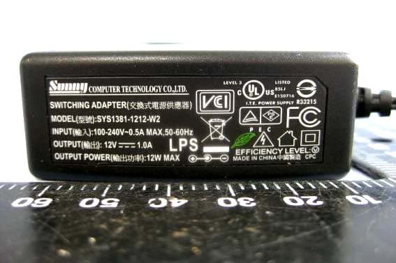
Click to zoom
Application Details
- Equipment Class
- DXX - Part 15 Low Power Communication Device Transmitter
- Date of Grant
- Jan 30, 2011
- Application Purpose
- Original Equipment
- Date of Application
- Jan 27, 2011
- Equipment Note
- Home Monitoring Gateway
- Frequency Range
- 908.40000000 - 908.40000000
- Company
- Sercomm Corporation
- Country
- Taiwan
Documents & Files
Document Text
Text extracted from the exhibit documents filed with the FCC. Open a document above to read the original.
Users Manual
Home Monitoring Gateway NA910 User Guide i Table of Contents CHAPTER 1 INTRODUCTION ............................................................................................. 1 Package Contents .............................................................................................................. 1 Specfication ........................................................................................................................ 1 LEDs ................................................................................................................................... 2 CHAPTER 2 INITIAL INSTALLATION .............................................................................. 5 Requirements ..................................................................................................................... 5 Procedure ........................................................................................................................... 5 CHAPTER 3 BOARD DESCRIPTION .................................................................................. 6 Components and connectors ............................................................................................ 6 Copyright © 2010. All Rights Reserved. Document Version: 1.0 All trademarks and trade names are the properties of their respective owners. 1 Chapter 1 Introduction This Chapter provides an overview of the Home Monitoring Gateway's fea- tures and capabilities. Congratulations on the purchase of your new Home Monitoring Gateway. The Home Monitor- ing Gateway is a consumer electronic device, which is used for home monitoring and security. Package Contents The following items should be included: • The Home Monitoring Gateway Unit • Power Adapter • A Stand If any of the above items are damaged or missing, please contact your dealer immediately. Specfication • DDR2 SDRAM 64MB • NAND 32MB Flash • Four Ethernet ports with RJ45 connectors. • Front Panel LEDs • Z-Wave module • Two USB 2.0 ports • Sync button • WPS button • Reset button • Power In connector • Two Internal antennae • 802.11bgn Wireless Functions 1 2 LEDs Front-mounted LEDs The Home Monitoring Gateway has 8 LEDs. Reset This button has two (2) functions: • Reboot. When pressed and released, the 11N Home Monitoring Gateway will reboot (restart). • Clear All Data. This button can also be used to clear ALL data and restore ALL settings to the factory default values. To Clear All Data and restore the factory default values: 1. Power On. 2. Keep holding the Reset Button down for 8 seconds. Release the Reset Button. The 11N Home Monitoring Gateway is now using the factory default values. WPS button Push the WPS button on the device and on your other wireless device to perform WPS function that easily creates an encryption-secured wireless connection automatically. Sync Button Push this button to synchronize for portal server or Z-Wave clients. POWER (Green) • On - Power On • Off - Power Off • Flashing - Reboot or Firmware upgrade. WAN (Green) • On - Connection to the Gateway attached to the WAN (Internet) port is established. • Off - No connection to the Gateway. • Flashing - Data is being transmitted or received via the connection. WiFi & WPS WiFi • On (Green) - Wireless connection available • Off (Green) - No Wireless connection available. • Flashing (Green) - Data is being transmitted or received via the Wireless connection. 3 WPS • On (Amber) - Problem occurred while trying to enable the WPS function. • On (Green) - WPS function is enabled. • Flashing - Data is being transmitted or received via the connection. Service • On (Green)- Control Point has made a successful activation to the Portal Server. • Off - No active connection to the Portal Server. • Flashing - Attempting to establish a connection to the Portal Server. LAN (Green) • On (Green)- LAN connection established. • Off - No active connection on the corresponding LAN port. • Flashing - Data is being transmitted or received via the correspond- ing LAN (hub) port. ZWave • On - ZWave function enabled. • Off - ZWave function disabled. • Flashing - Data is being transmitted or received via the connection. USB (1~2) • On (Green)- USB connection established. • Off - No active connection on the corresponding USB port. • Flashing - Data is being transmitted or received via the correspond- ing USB port. 4 Rear Panel WAN port (10/100BaseT) Connect the DSL or Cable Modem here. If your modem came with a cable, use the supplied cable. Otherwise, use a standard LAN cable. LAN (1~4) Port Use standard LAN cables (RJ45 connectors) to connect your PCs to these ports. USB (1~2) Port The two connectors are USB hosts with support for mass storage devices. RS232/RS422 terminal The terminal block includes transmit (tx)/receive (rx) connections and a GND port. Power Port Connect the supplied power adapter here. 5 Chapter 2 Initial Installation This Chapter covers the software installation of the Home Monitoring Gate- way. Requirements • Network cables. Use standard 10/100BaseT network (UTP) cables with RJ45 connectors. Procedure 1. Choose an Installation Site Select a suitable place to install the Home Monitoring Gateway. 2. Connect LAN Cables Use standard LAN cables to connect devices to the Ethernet ports on the Home Monitor- ing Gateway. 4. Power Up Connect the supplied power adapter to the Home Monitoring Gateway. Use only the power adapter provided. Using a different one may cause hardware damage. 5. Check the LEDs • The POWER LED should be ON. • The LAN LED should be ON (provided the PC is also ON.) 2 6 Chapter 3 Board Description This Chapter provides board description for the Home Monitoring Gateway. Components and connectors 1234 98765 10 11 • 1. RS422/RS232 connector • 2. USB type A connector • 3. LAN port • 4. WAN port • 5. Expansion slot connectors • 6. Push buttons. • 7. Console port • 8. LEDs • 9. RT3662 processor • 10. RS422/RS232 function select jumper • 11. DC power jack 3 7 Console port connection guide For …
Text truncated - open the document above for the full version.
External Photos
Compliance Certification Services Inc. Report No.: T101130209 Date of Issue: January 3, 2010 A1 - 1 Total Page: 21 Rev. 00 APPENDIX 1 - PHOTOGRAPHS OF EUT EXTERNAL PHOTOGRAPHS OF EUT For 802.11 b/g/n + Z-Wave module Compliance Certification Services Inc. Report No.: T101130209 Date of Issue: January 3, 2010 A1 - 2 Rev. 00 Compliance Certification Services Inc. Report No.: T101130209 Date of Issue: January 3, 2010 A1 - 3 Rev. 00 Adapter For SYS1381-1212-W2 Compliance Certification Services Inc. Report No.: T101130209 Date of Issue: January 3, 2010 A1 - 4 Rev. 00 For MU12-G120100-A1
ID Label/Location Info
Label Location
Internal Photos
Compliance Certification Services Inc. Report No.: T101130209 Date of Issue: January 3, 2010 A1 - 5 Rev. 00 INTERNAL PHOTOGRAPHS OF EUT For 802.11b/g/n + Z-Wave Compliance Certification Services Inc. Report No.: T101130209 Date of Issue: January 3, 2010 A1 - 6 Rev. 00 Z-Wave module WLAN Antenna C147-510674-A (SSR-210468) WLAN Antenna C147-510649-A (SSR-210213) WLAN Antenna C147-510652-A (SSR-209470) Compliance Certification Services Inc. Report No.: T101130209 Date of Issue: January 3, 2010 A1 - 7 Rev. 00 Compliance Certification Services Inc. Report No.: T101130209 Date of Issue: January 3, 2010 A1 - 8 Rev. 00 Compliance Certification Services Inc. Report No.: T101130209 Date of Issue: January 3, 2010 A1 - 9 Rev. 00 Compliance Certification Services Inc. Report No.: T101130209 Date of Issue: January 3, 2010 A1 - 10 Rev. 00 Compliance Certification Services Inc. Report No.: T101130209 Date of Issue: January 3, 2010 A1 - 11 Rev. 00 Compliance Certification Services Inc. Report No.: T101130209 Date of Issue: January 3, 2010 A1 - 12 Rev. 00 Compliance Certification Services Inc. Report No.: T101130209 Date of Issue: January 3, 2010 A1 - 13 Rev. 00 Compliance Certification Services Inc. Report No.: T101130209 Date of Issue: January 3, 2010 A1 - 14 Rev. 00 Compliance Certification Services Inc. Report No.: T101130209 Date of Issue: January 3, 2010 A1 - 15 Rev. 00 Compliance Certification Services Inc. Report No.: T101130209 Date of Issue: January 3, 2010 A1 - 16 Rev. 00 For Z-WAVE Antenna Z-WAVE Antenna Compliance Certification Services Inc. Report No.: T101130209 Date of Issue: January 3, 2010 A1 - 17 Rev. 00 Compliance Certification Services Inc. Report No.: T101130209 Date of Issue: January 3, 2010 A1 - 18 Rev. 00 Compliance Certification Services Inc. Report No.: T101130209 Date of Issue: January 3, 2010 A1 - 19 Rev. 00 For WLAN Antenna C147-510674-A (SSR-210468) Compliance Certification Services Inc. Report No.: T101130209 Date of Issue: January 3, 2010 A1 - 20 Rev. 00 For WLAN Antenna C147-510649-A (SSR-210213) Compliance Certification Services Inc. Report No.: T101130209 Date of Issue: January 3, 2010 A1 - 21 Rev. 00 For WLAN Antenna (C147-510652-A (SSR-209470))
Test Report
Compliance Certification Services Inc. Report No.: T101130209-RP3 FCC ID: P27NA910A Date of Issue: January 25, 2011 Note: This report shall not be reproduced except in full, without the written approval of Compliance Certification Services Inc. This document may be altered or revised by Compliance Certification Services Inc. personnel only, and shall be noted in the revision section of the document. Page 1 Total Page: 26 Rev. 00 FCC 47 CFR PART 15 Subpart C TEST REPORT For Home Monitoring Gateway Model: NA910 Trade Name: SerComm Issued to SerComm Corporation 8F, No.3-1, YuanQu St., NanKang, Taipei 115, Taiwan, R.O.C. Issued by Compliance Certification Services Inc. No.11, Wugong 6th Rd., Wugu Dist., Xinbei City 24891, Taiwan http://www.ccsrf.com [email protected] Compliance Certification Services Inc. Report No.: T101130209-RP3 FCC ID: P27NA910A Date of Issue: January 25, 2011 Page 2 Rev. 00 TABLE OF CONTENTS 1. TEST RESULT CERTIFICATION................................................................................................................ 3 2. EUT DESCRIPTION...................................................................................................................................... 4 3. TEST METHODOLOGY ............................................................................................................................... 5 3.1 EUT CONFIGURATION................................................................................................................. 5 3.2 EUT EXERCISE............................................................................................................................. 5 3.3 GENERAL TEST PROCEDURES...................................................................................................... 5 3.4 FCC PART 15.205 RESTRICTED BANDS OF OPERATIONS.................................................. 6 3.5 DESCRIPTION OF TEST MODES.................................................................................................... 6 4. INSTRUMENT CALIBRATION................................................................................................................... 7 4.1 MEASURING INSTRUMENT CALIBRATION............................................................................... 7 4.2 MEASUREMENT EQUIPMENT USED .................................................................................. 7 4.3 MEASUREMENT UNCERTAINTY ........................................................................................ 9 5. FACILITIES AND ACCREDITATIONS .................................................................................................... 10 5.1 FACILITIES ................................................................................................................................ 10 5.2 EQUIPMENT...............................................................................................................................10 5.3 TABLE OF ACCREDITATIONS AND LISTINGS.............................................................................. 11 6. SETUP OF EQUIPMENT UNDER TEST ...................................................................................................12 6.1 SETUP CONFIGURATION OF EUT................................................................................................ 12 6.2 SUPPORT EQUIPMENT ........................................................................................................ 12 7. FCC PART 15.249 REQUIREMENTS ........................................................................................................ 13 7.1 20 DB BANDWIDTH.............................................................................................................. 13 7.2 SPURIOUS EMISSION .......................................................................................................... 15 7.3 POWERLINE CONDUCTED EMISSIONS ........................................................................... 21 APPENDIX I PHOTOGRAPHS OF TEST SETUP ............................................................................................24 APPENDIX 1 - PHOTOGRAPHS OF EUT Compliance Certification Services Inc. Report No.: T101130209-RP3 FCC ID: P27NA910A Date of Issue: January 25, 2011 Page 3 Rev. 00 1. TEST RESULT CERTIFICATION Applicant: SerComm Corporation 8F, No.3-1, YuanQu St., NanKang, Taipei 115, Taiwan, R.O.C. Equipment Under Test: Home Monitoring Gateway Tr a d e N a m e : SerComm Model: NA910 Date of Test: December 2, 2010 ~ January 25, 2011 APPLICABLE STANDARDS STANDARD TEST RESULT FCC 47 CFR Part 15 Subpart C No non-compliance noted We hereby certify that: The above equipment was tested by Compliance Certification Services Inc. The test data, data evaluation, test procedures, and equipment configurations shown in this report were made in accordance with the procedures given in ANSI C63.4: 2003 and the energy emitted by the sample EUT tested as described in this report is in compliance with the requirements emission limits of FCC Rules Part 15.107, 15.109,15.207, 15.209 and 15.249. The test results of this report relate only to the tested sample identified in this report. Approved by: Reviewed by: Rex Lai Gina Lo Section Manager Section Manager Compliance Certification Services Inc. Compliance Certification Services Inc. Compliance Certification Services Inc. Report No.: T101130209-RP3 FCC ID: P27NA910A Date of Issue: January 25, 2011 Page 4 Rev. 00 2. EUT DESCRIPTION Product Home Monitoring Gateway Trade Name SerComm Model Number NA910 Model Discrepancy N/A Power Adapter 1. LEADER/ MU12-G120100-A1 I/P: 100-240V, 50-60Hz, 0.5A O/P: DC 12 V, 1.0 A 2. Sunny/ SYS1381-1212-W2 I/P: 100-240V, 50-60Hz, 0.5A O/P: DC 12 V, 1.0 A Frequency Range Z-WAVE: 908MHz Modulation Technique Z-WAVE: FSK Antenna Gain Z-WAVE: 2.21dBi Antenna Designation Z-WAVE: PCB Antenna Remark: 1. The sample selected for test was production product and was provided by manufacturer. 2. This submittal(s) (test report) is i…
Text truncated - open the document above for the full version.
Test Setup Photos
Compliance Certification Services Inc. Report No.: T101130209-RP3 FCC ID: P27NA910A Date of Issue: December 30, 2010 Page 24 Rev. 00 APPENDIX I PHOTOGRAPHS OF TEST SETUP Conducted Emission Set Up Photo Compliance Certification Services Inc. Report No.: T101130209-RP3 FCC ID: P27NA910A Date of Issue: December 30, 2010 Page 25 Rev. 00 Radiated Emission Set up Photos Compliance Certification Services Inc. Report No.: T101130209-RP3 FCC ID: P27NA910A Date of Issue: December 30, 2010 Page 26 Rev. 00 Powerline Conducted Emissions Setup Photos
Contact Information
Applicant
Nick Wu(Engineer)
Technical Contact
Compliance Certification Services Inc.Sandy Lin
[email protected]886-2-2299-9720
No. 11, Wugong 6th Rd, · Taipei Hsien · Taiwan
Test Firm
Compliance Certification Services Inc.Hank Lee
Technical Specifications
| # | Rule Parts | Frequency Range | Power Output |
|---|---|---|---|
| 1 | 15C | 908.4 MHz - 908.4 MHz | - |
Other Applications from Sercomm Corporation
P27-MOTIONZW60R0
Aug 04, 2026WIRELESS PIR MOTION SENSOR
Equipment Class
DTS - Digital Transmission SystemP27-SCP5173P
Dec 24, 2025Moso Canopy 5GOD2
Equipment Class
CBD - Citizens Band Category A and B DevicesP27-TPM530
Nov 24, 2025CATM1 Module
Equipment Class
PCB - PCS Licensed TransmitterP27MQIO
Sep 16, 2025Mqio 9W
Equipment Class
DTS - Digital Transmission SystemP27LORAAREAV2
Jul 25, 2024MachineQ Area 8C V2 LoRaWAN Gateway
Equipment Class
PCB - PCS Licensed Transmitter