P27RC8025Wireless Network Camera
Sercomm Corporation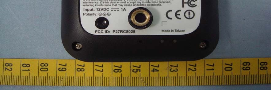
Click to zoom
Application Details
- Equipment Class
- DTS - Digital Transmission System
- Date of Grant
- Aug 21, 2012
- Application Purpose
- Original Equipment
- Date of Application
- Aug 21, 2012
- Equipment Note
- Wireless Network Camera
- Frequency Range
- 2422.00000000 - 2452.00000000
- Company
- Sercomm Corporation
- Country
- Taiwan
Documents & Files
Document Text
Text extracted from the exhibit documents filed with the FCC. Open a document above to read the original.
Users Manual
RC8025 User’s Guide i Table of Contents CHAPTER 1 INTRODUCTION.............................................................................................. 1 Overview ............................................................................................................................ 1 Physical Details - Network Camera ................................................................................. 2 Package Contents .............................................................................................................. 5 CHAPTER 2 BASIC SETUP ................................................................................................... 6 System Requirements........................................................................................................ 6 Installation ......................................................................................................................... 6 Setup using the Windows Wizard ................................................! Wall Mounting ...................................................................................................................8 Outdoor Installation........................................................................................................ 10 Ceiling Mounting ............................................................................................................. 12 CHAPTER 3 VIEWING LIVE VIDEO ................................................................................ 14 Overview .......................................................................................................................... 14 Requirements ...................................................................................................................14 Connecting to a Camera on your LAN .......................................................................... 14 Viewing Live Video ......................................................................................................... 16 APPENDIX A SPECIFICATIONS........................................................................................ 18 Network Camera ............................................................................................................. 18 Regulatory Approvals ..................................................................................................... 18 Copyright © 2012. All Rights Reserved. Document Version: 1.0 All trademarks and trade names are the properties of their respective owners. 1 Chapter 1 Introduction This Chapter provides information of the Network Camera's features, components and capabilities. Overview Congratulations on the purchase of your new Network Camera. The Network Camera is a True Day/Night Network Camera with VGA resolution and 802.11n WiFi connectivity. Features • Standalone Design. The Network Camera is a standalone system with built-in CPU and Video encoder. It requires only a power source and a connection to your Wireless iHub. • Multiple Video Compressions. The Network Camera supports H.264, MPEG4 and MJEPG video for different image compressions. • Suitable for Home, Business or Public Facilities. Whether for Home, Business or Public Facility surveillance, or just for entertainment and fun, the Network Camera has the features you need. Wireless Features • Supports 802.11n Wireless Standard. The 802.11n standard provides backward compatibility with the 802.11b and g standards. The Network Camera can work with all 802.11n, 802.11b and 802.11g Wireless stations. • Supports WPS. WPS (Wi-Fi Protected Setup) can simplify the process of connecting you Network Camera to your wireless network by using the push button configuration (PBC) on the Wireless Access Point, or entering a PIN code if there's no button. • Wired and Wireless Network. The Network Camera can be connected either with wire or wirelessly to your network. 1 2 Physical Details - Network Camera Front - Network Camera Figure 1: Front Panel IR LED IR LEDs provide illumination at night or in a dark environment. Daylight Sensor The sensor can be used to detect daylight levels and adjust the output lighting automatically. Night Mode Lens No physical adjustment is required for the lens. Please note that the image quality will be degraded if the lens cover is dirty or smudged. Day Mode Lens No physical adjustment is required for the lens. Please note that the image quality will be degraded if the lens cover is dirty or smudged. 3 Rear - Network Camera Figure 2: Rear Panel 1. External Antenna (Optional) This 1.8 dBi external antenna is an optional sku /kit for the Network Camera. 2. Power Input Connect the supplied 12V power adapter here. Do not use other power adapters; doing so may damage the camera. IMPORTANT DO NOT USE ANY OTHER ADAPTER OTHER THAN THIS ONE SPECIFIED FOR THIS CAMERA. DOING SO MAY DAMAGE THE NETWORK CAMERA. 3. LAN Port Use standard Ethernet cable (RJ45 connectors) to connect your PC to the port for installation and configuration. IMPORTANT PLUGGING IN THE ETHERNET CABLE WILL DISABLE THE WIRELESS INTERFACE. (ONLY ONE INTERFACE CAN BE ACTIVE AT ANY TIME.) THE ETHERNET CABLE SHOULD ONLY BE CONNECTED OR DISCONNECTED WHEN THE CAMERA IS POWER OFF. ATTACHED OR DETACHING THE ETHERNET CABLE WHILE THECAMERA IS POWERED ON DOES NOT SWITCH THE INTERFACE BETWEEN WIRED AND WIRELESS. DETACHING THE ETHERNET CABLE WHEN THE CAMERA IS POWERED ON WILL DISCONNECT THE CAMERA FROM THE NETWORK. 4 4. Reset This button has two (2) functions: • Reboot. When pressed briefly and released, the Network Camera will reboot (restart) itself. • Reset to Factory Default. To reset to factory defaults: 1. Power On until Camera’s Power and Network LED are static on. 2. Keep holding the Reset Button down for 10 seconds, then release, Camera will return to factory default setting. 5. Microphone The built-in microphone is located on the rear of the device. 6. Power Indicator (Green) On - Power is on. Off - Power is off. Flashing - The Po…
Text truncated - open the document above for the full version.
Users Manual
RC8025 User’s Guide i Table of Contents CHAPTER 1 INTRODUCTION.............................................................................................. 1 Overview ............................................................................................................................ 1 Physical Details - Network Camera ................................................................................. 2 Package Contents .............................................................................................................. 5 CHAPTER 2 BASIC SETUP ................................................................................................... 6 System Requirements........................................................................................................ 6 Installation ......................................................................................................................... 6 Setup using the Windows Wizard ................................................! Wall Mounting ...................................................................................................................8 Outdoor Installation........................................................................................................ 10 Ceiling Mounting ............................................................................................................. 12 CHAPTER 3 VIEWING LIVE VIDEO ................................................................................ 14 Overview .......................................................................................................................... 14 Requirements ...................................................................................................................14 Connecting to a Camera on your LAN .......................................................................... 14 Viewing Live Video ......................................................................................................... 16 APPENDIX A SPECIFICATIONS........................................................................................ 18 Network Camera ............................................................................................................. 18 Regulatory Approvals ..................................................................................................... 18 Copyright © 2012. All Rights Reserved. Document Version: 1.0 All trademarks and trade names are the properties of their respective owners. 1 Chapter 1 Introduction This Chapter provides information of the Network Camera's features, components and capabilities. Overview Congratulations on the purchase of your new Network Camera. The Network Camera is a True Day/Night Network Camera with VGA resolution and 802.11n WiFi connectivity. Features • Standalone Design. The Network Camera is a standalone system with built-in CPU and Video encoder. It requires only a power source and a connection to your Wireless iHub. • Multiple Video Compressions. The Network Camera supports H.264, MPEG4 and MJEPG video for different image compressions. • Suitable for Home, Business or Public Facilities. Whether for Home, Business or Public Facility surveillance, or just for entertainment and fun, the Network Camera has the features you need. Wireless Features • Supports 802.11n Wireless Standard. The 802.11n standard provides backward compatibility with the 802.11b and g standards. The Network Camera can work with all 802.11n, 802.11b and 802.11g Wireless stations. • Supports WPS. WPS (Wi-Fi Protected Setup) can simplify the process of connecting you Network Camera to your wireless network by using the push button configuration (PBC) on the Wireless Access Point, or entering a PIN code if there's no button. • Wired and Wireless Network. The Network Camera can be connected either with wire or wirelessly to your network. 1 2 Physical Details - Network Camera Front - Network Camera Figure 1: Front Panel IR LED IR LEDs provide illumination at night or in a dark environment. Daylight Sensor The sensor can be used to detect daylight levels and adjust the output lighting automatically. Night Mode Lens No physical adjustment is required for the lens. Please note that the image quality will be degraded if the lens cover is dirty or smudged. Day Mode Lens No physical adjustment is required for the lens. Please note that the image quality will be degraded if the lens cover is dirty or smudged. 3 Rear - Network Camera Figure 2: Rear Panel 1. External Antenna (Optional) This 1.8 dBi external antenna is an optional sku /kit for the Network Camera. 2. Power Input Connect the supplied 12V power adapter here. Do not use other power adapters; doing so may damage the camera. IMPORTANT DO NOT USE ANY OTHER ADAPTER OTHER THAN THIS ONE SPECIFIED FOR THIS CAMERA. DOING SO MAY DAMAGE THE NETWORK CAMERA. 3. LAN Port Use standard Ethernet cable (RJ45 connectors) to connect your PC to the port for installation and configuration. IMPORTANT PLUGGING IN THE ETHERNET CABLE WILL DISABLE THE WIRELESS INTERFACE. (ONLY ONE INTERFACE CAN BE ACTIVE AT ANY TIME.) THE ETHERNET CABLE SHOULD ONLY BE CONNECTED OR DISCONNECTED WHEN THE CAMERA IS POWER OFF. ATTACHED OR DETACHING THE ETHERNET CABLE WHILE THECAMERA IS POWERED ON DOES NOT SWITCH THE INTERFACE BETWEEN WIRED AND WIRELESS. DETACHING THE ETHERNET CABLE WHEN THE CAMERA IS POWERED ON WILL DISCONNECT THE CAMERA FROM THE NETWORK. 4 4. Reset This button has two (2) functions: • Reboot. When pressed briefly and released, the Network Camera will reboot (restart) itself. • Reset to Factory Default. To reset to factory defaults: 1. Power On until Camera’s Power and Network LED are static on. 2. Keep holding the Reset Button down for 10 seconds, then release, Camera will return to factory default setting. 5. Microphone The built-in microphone is located on the rear of the device. 6. Power Indicator (Green) On - Power is on. Off - Power is off. Flashing - The Po…
Text truncated - open the document above for the full version.
Users Manual
RC8025 User’s Guide i Table of Contents CHAPTER 1 INTRODUCTION.............................................................................................. 1 Overview ............................................................................................................................ 1 Physical Details - Network Camera ................................................................................. 2 Package Contents .............................................................................................................. 5 CHAPTER 2 BASIC SETUP ................................................................................................... 6 System Requirements........................................................................................................ 6 Installation ......................................................................................................................... 6 Setup using the Windows Wizard ................................................! Wall Mounting ...................................................................................................................8 Outdoor Installation........................................................................................................ 10 Ceiling Mounting ............................................................................................................. 12 CHAPTER 3 VIEWING LIVE VIDEO ................................................................................ 14 Overview .......................................................................................................................... 14 Requirements ...................................................................................................................14 Connecting to a Camera on your LAN .......................................................................... 14 Viewing Live Video ......................................................................................................... 16 APPENDIX A SPECIFICATIONS........................................................................................ 18 Network Camera ............................................................................................................. 18 Regulatory Approvals ..................................................................................................... 18 Copyright © 2012. All Rights Reserved. Document Version: 1.0 All trademarks and trade names are the properties of their respective owners. 1 Chapter 1 Introduction This Chapter provides information of the Network Camera's features, components and capabilities. Overview Congratulations on the purchase of your new Network Camera. The Network Camera is a True Day/Night Network Camera with VGA resolution and 802.11n WiFi connectivity. Features • Standalone Design. The Network Camera is a standalone system with built-in CPU and Video encoder. It requires only a power source and a connection to your Wireless iHub. • Multiple Video Compressions. The Network Camera supports H.264, MPEG4 and MJEPG video for different image compressions. • Suitable for Home, Business or Public Facilities. Whether for Home, Business or Public Facility surveillance, or just for entertainment and fun, the Network Camera has the features you need. Wireless Features • Supports 802.11n Wireless Standard. The 802.11n standard provides backward compatibility with the 802.11b and g standards. The Network Camera can work with all 802.11n, 802.11b and 802.11g Wireless stations. • Supports WPS. WPS (Wi-Fi Protected Setup) can simplify the process of connecting you Network Camera to your wireless network by using the push button configuration (PBC) on the Wireless Access Point, or entering a PIN code if there's no button. • Wired and Wireless Network. The Network Camera can be connected either with wire or wirelessly to your network. 1 2 Physical Details - Network Camera Front - Network Camera Figure 1: Front Panel IR LED IR LEDs provide illumination at night or in a dark environment. Daylight Sensor The sensor can be used to detect daylight levels and adjust the output lighting automatically. Night Mode Lens No physical adjustment is required for the lens. Please note that the image quality will be degraded if the lens cover is dirty or smudged. Day Mode Lens No physical adjustment is required for the lens. Please note that the image quality will be degraded if the lens cover is dirty or smudged. 3 Rear - Network Camera Figure 2: Rear Panel 1. External Antenna (Optional) This 1.8 dBi external antenna is an optional sku /kit for the Network Camera. 2. Power Input Connect the supplied 12V power adapter here. Do not use other power adapters; doing so may damage the camera. IMPORTANT DO NOT USE ANY OTHER ADAPTER OTHER THAN THIS ONE SPECIFIED FOR THIS CAMERA. DOING SO MAY DAMAGE THE NETWORK CAMERA. 3. LAN Port Use standard Ethernet cable (RJ45 connectors) to connect your PC to the port for installation and configuration. IMPORTANT PLUGGING IN THE ETHERNET CABLE WILL DISABLE THE WIRELESS INTERFACE. (ONLY ONE INTERFACE CAN BE ACTIVE AT ANY TIME.) THE ETHERNET CABLE SHOULD ONLY BE CONNECTED OR DISCONNECTED WHEN THE CAMERA IS POWER OFF. ATTACHED OR DETACHING THE ETHERNET CABLE WHILE THECAMERA IS POWERED ON DOES NOT SWITCH THE INTERFACE BETWEEN WIRED AND WIRELESS. DETACHING THE ETHERNET CABLE WHEN THE CAMERA IS POWERED ON WILL DISCONNECT THE CAMERA FROM THE NETWORK. 4 4. Reset This button has two (2) functions: • Reboot. When pressed briefly and released, the Network Camera will reboot (restart) itself. • Reset to Factory Default. To reset to factory defaults: 1. Power On until Camera’s Power and Network LED are static on. 2. Keep holding the Reset Button down for 10 seconds, then release, Camera will return to factory default setting. 5. Microphone The built-in microphone is located on the rear of the device. 6. Power Indicator (Green) On - Power is on. Off - Power is off. Flashing - The Po…
Text truncated - open the document above for the full version.
Cover Letter(s)
SerComm Corporation中磊電子股份有限公司 Taipei Office: 8F, No.3-1, YuanQu St., NanKang, Taipei 115, Taiwan, R.O.C. TEL: 886-2-2655-3988 FAX: 886-2-2655-3966 Chu Nan Office: 3F, No. 81, YuYi Rd., Chu-Nan, Miao-Li 350, Taiwan, R.O.C. TEL: 886-37-585-899 FAX: 886-37-585-000 Date:July 25, 2012 BABT TCB Forsyth House, Churchfield Road, Walton-on-Thames, Surrey, KT12 2TD Confidentiality Request FCC ID: P27RC8025 Pursuant to Sections 0.457(d)(1)(ii) and 0.459 of the Commission’s Rules, SerComm Corporation hereby requests permanent confidential treatment of information accompanying this application as outlined below: Common exhibits for which confidentiality is requested are: Schematics Block Diagrams Theory of Operation The above materials contain trade secrets and proprietary information not customarily released to the public. The public disclosure of these matters might be harmful to the Applicant and provide unjustified benefits to its competitors. The Applicant understands that pursuant to Rule 0.457(d)(1)(ii), disclosure of this Application and all accompanying materials will not be made before the date of the Grant for this Application. Your Sincerely, Ronnie Cheng Associate Manager / R&D Division SerComm Corporation TEL: 886-2-2655-3988#2547 FAX: 886-2-2655-7379 E-Mail: [email protected]
Cover Letter(s)
SerComm Corporation中磊電子股份有限公司 Taipei Office: 8F, No.3-1, YuanQu St., NanKang, Taipei 115, Taiwan, R.O.C. TEL: 886-2-2655-3988 FAX: 886-2-2655-3966 Chu Nan Office: 3F, No. 81, YuYi Rd., Chu-Nan, Miao-Li 350, Taiwan, R.O.C. TEL: 886-37-585-899 FAX: 886-37-585-000 Date:July 25, 2012 Subject:DoC declaration To Whom it may concern, We, as the grantee of this project FCC ID: P27RC8025, would like to declare that the composite Portion categorized as computer peripheral has been authorized under the Declaration of Conformity procedures. Brand Name & Model Name of the specified radio equipment: SerComm/ RC8025xxxxxxxx(x= 0~9, A~Z, Blank or any Character) FCC ID: P27RC8025 Product Name: Wireless Network Camera Regards, Your Sincerely, Ronnie Cheng Associate Manager / R&D Division SerComm Corporation TEL: 886-2-2655-3988#2547 FAX: 886-2-2655-7379 E-Mail: [email protected]
Cover Letter(s)
SerComm Corporation中磊電子股份有限公司 Taipei Office: 8F, No.3-1, YuanQu St., NanKang, Taipei 115, Taiwan, R.O.C. TEL: 886-2-2655-3988 FAX: 886-2-2655-3966 Chu Nan Office: 3F, No. 81, YuYi Rd., Chu-Nan, Miao-Li 350, Taiwan, R.O.C. TEL: 886-37-585-899 FAX: 886-37-585-000 Date:July 25, 2012 BABT TCB Forsyth House, Churchfield Road, Walton-on-Thames, Surrey, KT12 2TD Confidentiality Request FCC ID: P27RC8025 Pursuant to Sections 0.457(d)(1)(ii) and 0.459 of the Commission’s Rules, SerComm Corporation hereby requests permanent confidential treatment of information accompanying this application as outlined below: Common exhibits for which confidentiality is requested are: Schematics Block Diagrams Theory of Operation The above materials contain trade secrets and proprietary information not customarily released to the public. The public disclosure of these matters might be harmful to the Applicant and provide unjustified benefits to its competitors. The Applicant understands that pursuant to Rule 0.457(d)(1)(ii), disclosure of this Application and all accompanying materials will not be made before the date of the Grant for this Application. Your Sincerely, Ronnie Cheng Associate Manager / R&D Division SerComm Corporation TEL: 886-2-2655-3988#2547 FAX: 886-2-2655-7379 E-Mail: [email protected]
Cover Letter(s)
SerComm Corporation中磊電子股份有限公司 Taipei Office: 8F, No.3-1, YuanQu St., NanKang, Taipei 115, Taiwan, R.O.C. TEL: 886-2-2655-3988 FAX: 886-2-2655-3966 Chu Nan Office: 3F, No. 81, YuYi Rd., Chu-Nan, Miao-Li 350, Taiwan, R.O.C. TEL: 886-37-585-899 FAX: 886-37-585-000 Date:July 25, 2012 Subject:DoC declaration To Whom it may concern, We, as the grantee of this project FCC ID: P27RC8025, would like to declare that the composite Portion categorized as computer peripheral has been authorized under the Declaration of Conformity procedures. Brand Name & Model Name of the specified radio equipment: SerComm/ RC8025xxxxxxxx(x= 0~9, A~Z, Blank or any Character) FCC ID: P27RC8025 Product Name: Wireless Network Camera Regards, Your Sincerely, Ronnie Cheng Associate Manager / R&D Division SerComm Corporation TEL: 886-2-2655-3988#2547 FAX: 886-2-2655-7379 E-Mail: [email protected]
Cover Letter(s)
SerComm Corporation中磊電子股份有限公司 Taipei Office: 8F, No.3-1, YuanQu St., NanKang, Taipei 115, Taiwan, R.O.C. TEL: 886-2-2655-3988 FAX: 886-2-2655-3966 Chu Nan Office: 3F, No. 81, YuYi Rd., Chu-Nan, Miao-Li 350, Taiwan, R.O.C. TEL: 886-37-585-899 FAX: 886-37-585-000 Date:July 25, 2012 BABT TCB Forsyth House, Churchfield Road, Walton-on-Thames, Surrey, KT12 2TD Confidentiality Request FCC ID: P27RC8025 Pursuant to Sections 0.457(d)(1)(ii) and 0.459 of the Commission’s Rules, SerComm Corporation hereby requests permanent confidential treatment of information accompanying this application as outlined below: Common exhibits for which confidentiality is requested are: Schematics Block Diagrams Theory of Operation The above materials contain trade secrets and proprietary information not customarily released to the public. The public disclosure of these matters might be harmful to the Applicant and provide unjustified benefits to its competitors. The Applicant understands that pursuant to Rule 0.457(d)(1)(ii), disclosure of this Application and all accompanying materials will not be made before the date of the Grant for this Application. Your Sincerely, Ronnie Cheng Associate Manager / R&D Division SerComm Corporation TEL: 886-2-2655-3988#2547 FAX: 886-2-2655-7379 E-Mail: [email protected]
Cover Letter(s)
SerComm Corporation中磊電子股份有限公司 Taipei Office: 8F, No.3-1, YuanQu St., NanKang, Taipei 115, Taiwan, R.O.C. TEL: 886-2-2655-3988 FAX: 886-2-2655-3966 Chu Nan Office: 3F, No. 81, YuYi Rd., Chu-Nan, Miao-Li 350, Taiwan, R.O.C. TEL: 886-37-585-899 FAX: 886-37-585-000 Date:July 25, 2012 Subject:DoC declaration To Whom it may concern, We, as the grantee of this project FCC ID: P27RC8025, would like to declare that the composite Portion categorized as computer peripheral has been authorized under the Declaration of Conformity procedures. Brand Name & Model Name of the specified radio equipment: SerComm/ RC8025xxxxxxxx(x= 0~9, A~Z, Blank or any Character) FCC ID: P27RC8025 Product Name: Wireless Network Camera Regards, Your Sincerely, Ronnie Cheng Associate Manager / R&D Division SerComm Corporation TEL: 886-2-2655-3988#2547 FAX: 886-2-2655-7379 E-Mail: [email protected]
External Photos
Report No: T120711D05 Page 1 / 13 Rev.00 EXTERNAL HOTOGRAPHS OF EUT Type 1 Report No: T120711D05 Page 2 Rev.00 Report No: T120711D05 Page 3 Rev.00 Report No: T120711D05 Page 4 Rev.00 Type 2 Report No: T120711D05 Page 5 Rev.00 SYS1381-1212-W2 Report No: T120711D05 Page 6 Rev.00 MU12-G120100-A1
External Photos
Report No: T120711D05 Page 1 / 13 Rev.00 EXTERNAL HOTOGRAPHS OF EUT Type 1 Report No: T120711D05 Page 2 Rev.00 Report No: T120711D05 Page 3 Rev.00 Report No: T120711D05 Page 4 Rev.00 Type 2 Report No: T120711D05 Page 5 Rev.00 SYS1381-1212-W2 Report No: T120711D05 Page 6 Rev.00 MU12-G120100-A1
External Photos
Report No: T120711D05 Page 1 / 13 Rev.00 EXTERNAL HOTOGRAPHS OF EUT Type 1 Report No: T120711D05 Page 2 Rev.00 Report No: T120711D05 Page 3 Rev.00 Report No: T120711D05 Page 4 Rev.00 Type 2 Report No: T120711D05 Page 5 Rev.00 SYS1381-1212-W2 Report No: T120711D05 Page 6 Rev.00 MU12-G120100-A1
Internal Photos
Report No: T120711D05 Page 7 Rev.00 INTERNAL HOTOGRAPHS OF EUT Antenna Report No: T120711D05 Page 8 Rev.00 Report No: T120711D05 Page 9 Rev.00 Report No: T120711D05 Page 10 Rev.00 Report No: T120711D05 Page 11 Rev.00 Report No: T120711D05 Page 12 Rev.00 Report No: T120711D05 Page 13 Rev.00
Internal Photos
Report No: T120711D05 Page 7 Rev.00 INTERNAL HOTOGRAPHS OF EUT Antenna Report No: T120711D05 Page 8 Rev.00 Report No: T120711D05 Page 9 Rev.00 Report No: T120711D05 Page 10 Rev.00 Report No: T120711D05 Page 11 Rev.00 Report No: T120711D05 Page 12 Rev.00 Report No: T120711D05 Page 13 Rev.00
Internal Photos
Report No: T120711D05 Page 7 Rev.00 INTERNAL HOTOGRAPHS OF EUT Antenna Report No: T120711D05 Page 8 Rev.00 Report No: T120711D05 Page 9 Rev.00 Report No: T120711D05 Page 10 Rev.00 Report No: T120711D05 Page 11 Rev.00 Report No: T120711D05 Page 12 Rev.00 Report No: T120711D05 Page 13 Rev.00
RF Exposure Info
Compliance Certification Services Inc. Report No.: T120711D05-RP1 FCC ID: P27RC8025 Date of Issue: July 27, 2012 Page 110 Rev.00 This report shall not be reproduced except in full, without the written approval of Compliance Certification Services. 8. APPENDIX I RADIO FREQUENCY EXPOSURE LIMIT According to §15.247(i), systems operating under the provisions of this section shall be operated in a manner that ensures that the public is not exposed to radio frequency energy levels in excess of the Commission's guidelines. See § 1.1307(b)(1) of this chapter. EUT Specification EUT Wireless Network Camera Frequency band (Operating) WLAN: 2.412GHz ~ 2.462GHz WLAN: 5.18GHz ~ 5.32GHz / 5.50GHz ~ 5.70GHz WLAN: 5.745GHz ~ 5.825GHz Others Device category Portable (<20cm separation) Mobile (>20cm separation) Others Exposure classification Occupational/Controlled exposure (S = 5mW/cm 2 ) General Population/Uncontrolled exposure (S=1mW/cm 2 ) Antenna diversity Single antenna Multiple antennas Tx diversity Rx diversity Tx/Rx diversity Max. output power IEEE 802.11b mode: 21.01 dBm (0.12618W) IEEE 802.11g mode: 24.41 dBm (0.21928W) draft 802.11n 20 MHz Channel mode: 26.00 dBm (0.39796W) draft 802.11n 40 MHz Channel mode: 25.64 dBm (0.36678W) Antenna gain (Max) 3.58dBi (including cable loss) (Numeric gain: 2.28) Evaluation applied MPE Evaluation SAR Evaluation N/A Remark: 1. The maximum output power is 26.00dBm (398.11W) at 2462MHz (with 2.28numeric antenna gain.) 2. For mobile or fixed location transmitters, no SAR consideration applied. The maximum power density is 1.0 mW/cm 2 even if the calculation indicates that the power density would be larger. TEST RESULTS No non-compliance noted. Compliance Certification Services Inc. Report No.: T120711D05-RP1 FCC ID: P27RC8025 Date of Issue: July 27, 2012 Page 111 Rev.00 This report shall not be reproduced except in full, without the written approval of Compliance Certification Services. Calculation Given d GP E ×× = 30 & 3770 2 E S= Where E = Field strength in Volts / meter P = Power in Watts G = Numeric antenna gain d = Distance in meters S = Power density in milliwatts / square centimeter Combining equations and re-arranging the terms to express the distance as a function of the remaining variables yields: 2 3770 30 d GP S ×× = Changing to units of mW and cm, using: P (mW) = P (W) / 1000 and d (cm) = d(m) / 100 Yields () () 2 2 0796.0 100/3770 1000/30 d GP d GP S × ×= × ×× = Equation 1 Where d = Distance in cm P = Power in mW G = Numeric antenna gain S = Power density in mW / cm 2 Maximum Permissible Exposure EUT output power = 398.11mW Numeric Antenna gain = 2.28 Substituting the MPE safe distance using d = 20 cm into Equation 1: Yields GPS××=000199.0 Where P = Power in mW G = Numeric antenna gain S = Power density in mW / cm 2 Æ Power density = 0.181 mW / cm 2 (For mobile or fixed location transmitters, the maximum power density is 1.0 mW/cm 2 even if the calculation indicates that the power density would be larger.)
RF Exposure Info
Compliance Certification Services Inc. Report No.: T120711D05-RP1 FCC ID: P27RC8025 Date of Issue: July 27, 2012 Page 110 Rev.00 This report shall not be reproduced except in full, without the written approval of Compliance Certification Services. 8. APPENDIX I RADIO FREQUENCY EXPOSURE LIMIT According to §15.247(i), systems operating under the provisions of this section shall be operated in a manner that ensures that the public is not exposed to radio frequency energy levels in excess of the Commission's guidelines. See § 1.1307(b)(1) of this chapter. EUT Specification EUT Wireless Network Camera Frequency band (Operating) WLAN: 2.412GHz ~ 2.462GHz WLAN: 5.18GHz ~ 5.32GHz / 5.50GHz ~ 5.70…
Text truncated - open the document above for the full version.
Contact Information
Applicant
Nick Wu(Engineer)
Test Firm
Compliance Certification Services Inc.Kurt Chen
Technical Specifications
| # | Rule Parts | Frequency Range | Power Output |
|---|---|---|---|
| 2 | 15C | 2.42 GHz - 2.45 GHz | 366.78 mW |
Other Applications from Sercomm Corporation
P27-MOTIONZW60R0
Aug 04, 2026WIRELESS PIR MOTION SENSOR
Equipment Class
DTS - Digital Transmission SystemP27-SCP5173P
Dec 24, 2025Moso Canopy 5GOD2
Equipment Class
CBD - Citizens Band Category A and B DevicesP27-TPM530
Nov 24, 2025CATM1 Module
Equipment Class
PCB - PCS Licensed TransmitterP27MQIO
Sep 16, 2025Mqio 9W
Equipment Class
DTS - Digital Transmission SystemP27LORAAREAV2
Jul 25, 2024MachineQ Area 8C V2 LoRaWAN Gateway
Equipment Class
PCB - PCS Licensed Transmitter