P27SSH1R0Window Sensor
Sercomm Corporation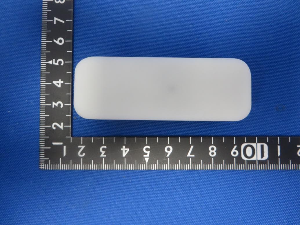
Click to zoom
Application Details
- Equipment Class
- PUB - Part 15 Unlicensed PCS Base Station
- Date of Grant
- Jan 29, 2020
- Application Purpose
- Original Equipment
- Date of Application
- Jan 05, 2020
- Equipment Note
- Window Sensor
- Frequency Range
- 1921.53600000 - 1928.44800000
- Company
- Sercomm Corporation
- Country
- Taiwan
Documents & Files
Document Text
Text extracted from the exhibit documents filed with the FCC. Open a document above to read the original.
Users Manual
1 SD-DWS07 Door/Window Sensor Installation Guide Door/Window sensors are designed to secure the perimeter of the residential premise, and provide the ability to add various automation services. The Door/Window sensor, which consists of a magnet that attaches to a door or window, will communicate door events to the home control system or security panel. When the magnet is moved away from the sensor, a signal will be sent to the control panel that communicates the changed state to the security system. Frequency 2.4GHz Battery Type CR2 Battery * 1 Operating Temperature 0 C to 40 C (32°F - 104°F) at 90% RH Non-condensing Storage Temperature -10 C to 60 C (14°F - 140°F) Battery Life 4 Years (20 trigger events per day @Room Temperature 25°C) Dimension Sensor Device: 67.5 mm x 24 mm x 20 mm (2" x 1.14" x 0.43") Magnet: 43 mm x 9.5 mm x 15 mm (2" x 0.39" x 0.43") Initiate pairing on your home control system or security panel using the instructions provided with it 1. Pull the exposed plastic tab from the sensor. (Figure 1) 2. The LED indicator will be lit for every seconds to indicate the sensor is booting successfully 3. It will blink one time per seconds while attempting to pair with the security panel or home controller. 4. If network is not found after 90 seconds, the sensor will go into sleep mode. To wake the sensor again, you need to use magnet or tamper (Figure 2) to trigger a paring process, and then sensor will repeat steps from 3 to 4. 1. Please make sure that the sensor and magnet is located less than 10 mm from each other. For optimal performance, it is highly recommended to install the Door/Window sensor on the fixed frame and the magnet on the moving part of the door/window. Place the sensor near the top of the door that close to the opening edge of the door. This is the mounting location for the sensor. 2. Use the provided double-sided tape on the sensor. Attach the sensor to the door. Press firmly and hold in place for a few seconds 3. Use provided double-sided tape on the magnet. Make sure the alignment of both sensor and magnet are facing each other (Figure 3). Press firmly and hold in place for a few seconds. 1. The Green Pairing LED will stay off during the normal operation. 2. The sensor is equipped with a tamper switch. If the cover of sensor is removed, the sensor will send an alarm to the home controller or security system. Introduction Specification Installation Pairing Sensor Operation Figure 3 Figure 2 Figure 1 2 If sensor needs to be factory defaulted (for example, to prepare it for joining with a home controller or security system). 1. Remove sensor cover. 2. Remove the CR2 battery from sensor. 3. Depress the tamper switch before inserting the battery. 4. Insert the battery. The sensor should illuminate the LED once when boot-up/initialization tasks are complete. 5. Release the tamper switch while the LED is illuminated (it will be lit for 4 seconds). The sensor should then reset to factory default settings and begin searching for any available home controller or security system. If you need to reboot the device, remove the battery, depress and release the tamper switch one time, then re-insert the battery. 6. Place the cover back on sensor. Note: Replace Battery with CR2 only. Use of another battery may negatively impact the performance of the product. FCC Statement: This equipment has been tested and found to comply with the limits for a Class B digital device, pursuant to Part 15 of the FCC Rules. These limits are designed to provide reasonable protection against harmful interference in a residential installation. This equipment generates, uses and can radiate radio frequency energy and, if not installed and used in accordance with the instructions, may cause harmful interference to radio communications. However, there is no guarantee that interference will not occur in a particular installation. If this equipment does cause harmful interference to radio or television reception, which can be determined by turning the equipment off and on, the user is encouraged to try to correct the interference by one of the following measures: • Reorient or relocate the receiving antenna. • Increase the separation between the equipment and receiver. • Connect the equipment into an outlet on a circuit different from that to which the receiver is connected. • Consult the dealer or an experienced radio/TV technician for help. The FCC ID for this device is P27SSH1R0 You are cautioned that changes or modifications not expressly approved by the party responsible for compliance could void your authority to operate the equipment. This device complies with Part 15 of the FCC Rules. Operation is subject to the following two conditions: (1) This device may not cause harmful interference, and (2) This device must accept any interference received, including interference that may cause undesired operation. FCC RF Radiation Exposure Statement: • This Transmitter must not be co-located or operating in conjunction with any other antenna or transmitter. • This equipment complies with FCC RF radiation exposure limits set forth for an uncontrolled environment. This equipment should be installed and operated with a minimum distance of 20 centimeters between the radiator and your body. Reset to Factory Defaults & Reboot Certification
Cover Letter(s)
DeclarationofAuthorization We Name:SercommCorporation Address:8F,No.3-1,YuanQuSt.,NanKang,Taipei115,Taiwan,R.O.C. Declarethat: NameRepresentativeofagent:MarlinChen AgentCompanyname:MRTTechnology(Suzhou)Co.,Ltd Address:D8Building,YouxinIndustrialPark,No.2Tian'edangRd., WuzhongEconomicDevelopmentZone, City:Suzhou CountryChina isauthorizedtoapplyforCertificationofthefollowingproduct(s): Productdescription:WindowSensor Typedesignation:SSH1R0-29xxxxx(the1stxshouldbe"blank"or"-";therestxcouldbe0to9, AtoZ,atoz,"blank"or"-",forthemarketingpurpose) FCCID:P27SSH1R0 Trademark:ADT onourbehalf. Date:December19,2019 Name:NickWu Signature:
Cover Letter(s)
Date:December19,2019 FederalCommunicationsCommission AuthorizationandEvaluationDivision FCCID:P27SSH1R0 ConfidentialityRequest PursuanttoSections0.457and0.459oftheCommission’sRules,weherebyrequest confidentialtreatmentofinformationaccompanyingthisapplicationasoutlinedbelow: 1.Block Diagram 2.Schematics 3.OperationDescription Theabovematerialscontaintradesecretsandproprietaryinformationnotcustomarily releasedtothepublic.Thepublicdisclosureofthesemattersmightbeharmfultothe applicantandprovideunjustifiedbenefitstoitscompetitors. TheapplicantunderstandsthatpursuanttoRule0.457,disclosureofthisapplicationand allaccompanyingdocumentationwillnotbemadebeforethedateoftheGrantforthis application. Sincerely, ---------------------------------------------------------- Name:NickWu SercommCorporation
External Photos
Report No.: 1912RSU041-UE 1 of 3 EUT Photograph (1) EUT Photo (2) EUT Photo Report No.: 1912RSU041-UE 2 of 3 (3) EUT Photo (4) EUT Photo Report No.: 1912RSU041-UE 3 of 3 (5) EUT Photo (6) EUT Photo
ID Label/Location Info
Label Location
Internal Photos
Report No.: 1912RSU041-UE 1 of 3 EUT Photograph (1) EUT Photo (2) EUT Photo Report No.: 1912RSU041-UE 2 of 3 (3) EUT Photo (4) EUT Photo Report No.: 1912RSU041-UE 3 of 3 (5) EUT Photo
RF Exposure Info
MRT Technology (Suzhou) Co., Ltd Report No.: 1912RSU041-U1 Phone: +886-3-3288388 Report Version: V02 Web: www.mrt-cert.com Issue Date: 01-08-2020 FCC ID: P27SSH1R0 Page Number: 1 of 8 RF Exposure Evaluation Declaration FCC ID: P27SSH1R0 Applicant: Sercomm Corporation Application Type: Certification Product: Window Sensor Model No.: SSH1R0-29xxxxx (the 1st x should be "blank" or "-"; the rest x could be 0 to 9, A to Z, a to z, "blank" or "-", for the marketing purpose) Brand Name: ADT FCC Classification: Unlicensed PCS Base Station (PUB) Test Procedure(s): KDB 447498 D01v06 Test Date: December 20 ~ 30, 2019 Reviewed By: ( Sunny Sun ) Approved By: ( Robin Wu ) The test results relate only to the samples tested. The test results shown in the test report are traceable to the national/international standards through the calibration of the equipment and evaluated measurement uncertainty herein. The test report shall not be reproduced except in full without the written approval of MRT Technology (Suzhou) Co., Ltd. Report No.: 1912RSU041-U1 FCC ID: P27SSH1R0 Page Number: 2 of 8 Revision History Report No. Version Description Issue Date Note 1912RSU041-U1 Rev. 01 Initial Report 01-04-2020 Invalid 1912RSU041-U1 Rev. 02 Updated with TCB’s Comment 01-08-2020 Valid Report No.: 1912RSU041-U1 FCC ID: P27SSH1R0 Page Number: 3 of 8 General Information Applicant: Sercomm Corporation Applicant Address: 8F, No. 3-1, YuanQu St., NanKang, Taipei 115, Taiwan, R.O.C. Manufacturer: Sercomm Corporation Manufacturer Address: 8F, No. 3-1, YuanQu St., NanKang, Taipei 115, Taiwan, R.O.C. Test Site: MRT Technology (Suzhou) Co., Ltd Test Site Address: D8 Building, No.2 Tian’edang Rd., Wuzhong Economic Development Zone, Suzhou, China Test Device Serial No.: N/A Production Pre-Production Engineering Test Facility / Accreditations Measurements were performed at MRT Laboratory located in Tian’edang Rd., Suzhou, China. MRT facility is a FCC accredited (MRT Designation No. CN1166) test facility with the site description report on file and has met all the requirements specified in ANSI C63.4-2014. MRT facility is an IC registered (MRT Reg. No. 11384A-1) test laboratory with the site description on file at Industry Canada. MRT facility is a VCCI registered (R-20025, G-20034, C-20020, T-20020) test laboratory with the site description on file at VCCI Council. MRT Lab is accredited to ISO 17025 by the American Association for Laboratory Accreditation (A2LA) under the American Association for Laboratory Accreditation Program (A2LA Cert. No. 3628.01) in EMC, Telecommunications, Radio and SAR testing. Report No.: 1912RSU041-U1 FCC ID: P27SSH1R0 Page Number: 4 of 8 1. PRODUCT INFORMATION 1.1. Equipment Description Product Name: Window Sensor Model No.: SSH1R0-29xxxxx (the 1st x should be "blank" or "-"; the rest x could be 0 to 9, A to Z, a to z, "blank" or "-", for the marketing purpose) Brand Name: ADT DECT Specification: Frequency Range: 1921.536 ~ 1928.448MHz Number of Channels: 5 Maximum Output Power: 17.88dBm Type of Modulation: Digital (Gaussian Frequency Shift Keying) Antenna Gain: 2.47dBi Antenna Type: PCB Antenna Report No.: 1912RSU041-U1 FCC ID: P27SSH1R0 Page Number: 5 of 8 2. RF Exposure Evaluation 2.1. Limits SAR Test Exclusion Thresholds for 100 MHz – 6 GHz and ≤ 50 mm Approximate SAR Test Exclusion Power Thresholds at Selected Frequencies and Test Separation Distances are illustrated in the following Table. The equation and threshold in Note 1 must be applied to determine SAR test exclusion. MHz 5 10 15 20 25 mm 150 39 77 116 155 194 SAR Test Exclusion Threshold (mW) 300 27 55 82 110 137 450 22 45 67 89 112 835 16 33 49 66 82 900 16 32 47 63 79 1500 12 24 37 49 61 1900 11 22 33 44 54 2450 10 19 29 38 48 3600 8 16 24 32 40 5200 7 13 20 26 33 5400 6 13 19 26 32 5800 6 12 19 25 31 MHz 30 35 40 45 50 mm 150 232 271 310 349 387 SAR Test Exclusion Threshold (mW) 300 164 192 219 246 274 450 134 157 179 201 224 835 98 115 131 148 164 900 95 111 126 142 158 1500 73 86 98 110 122 1900 65 76 87 98 109 2450 57 67 77 86 96 3600 47 55 63 71 79 5200 39 46 53 59 66 5400 39 45 52 58 65 5800 37 44 50 56 62 Note: The 1-g and 10-g SAR test exclusion thresholds for 100 MHz to 6 GHz at test separation distances ≤ 50 mm are determined by: Report No.: 1912RSU041-U1 FCC ID: P27SSH1R0 Page Number: 6 of 8 [(max. power of channel, including tune-up tolerance, mW)/(min. test separation distance, mm)] * [√f(GHz)] ≤ 3.0 for 1-g SAR and ≤ 7.5 for 10-g extremity SAR, where ⚫ f(GHz) is the RF channel transmit frequency in GHz ⚫ Power and distance are rounded to the nearest mW and mm before calculation ⚫ The result is rounded to one decimal place for comparison ⚫ 3.0 and 7.5 are referred to as the numeric thresholds in the step 2 below The test exclusions are applicable only when the minimum test separation distance is ≤ 50 mm and for transmission frequencies between 100 MHz and 6 GHz. When the minimum test separation distance is < 5 mm, a distance of 5 mm according to 5) in section 4.1 is applied to determine SAR test exclusion. Report No.: 1912RSU041-U1 FCC ID: P27SSH1R0 Page Number: 7 of 8 2.2. Test Result of RF Exposure Evaluation Product Motion Sensor Test Item RF Exposure Evaluation Test Mode Frequency Band (MHz) Maximum EIRP(dBm) Duty Cycle Factor (dB) Frame Power (dBm) SAR Test Exclusion Threshold (mW) DECT 1921.536 ~ 1928.448 20.25 -13.80 6.45 11 Note 1: Both burst-averaged and calculated frame-averaged powers are included. Frame-averaged powers were calculated from the measured burst-averaged power by converting the slot powers into linear units and calculating the energy over 24 timeslots Frame Power = 4.416mW < 11mW Note 2: Per FCC KDB 447498 D01v06, the SAR exclusion threshold for distances<50mm is defined by the following equation: Based on the maximum EIRP and the antenna to use separation distance, SAR was not required; [(4.416mW/5)* √1.928] = 1.23 < 3.0 Note: When the minimum test separation distance is < 5 mm, a distance of 5…
Text truncated - open the document above for the full version.
Test Report
MRT Technology (Suzhou) Co., Ltd Report No.: 1912RSU041-U1 Phone: +86-512-66308358 Report Version: V01 Web: www.mrt-cert.com Issue Date: 01-04-2020 FCC ID: P27SSH1R0 Page Number: 1 of 44 FCC ID: P27SSH1R0 Applicant: Sercomm Corporation Application Type: Certification Product: Window Sensor Model No.: SSH1R0-29xxxxx (the 1st x should be "blank" or "-"; the rest x could be 0 to 9, A to Z, a to z, "blank" or "-", for the marketing purpose) Brand Name: ADT FCC Classification: Unlicensed PCS Base Station FCC Rule Part(s): FCC Part 15 Subpart D Test Procedure(s): ANSI C63.17-2013 Test Date: December 20 ~ 30, 2019 MEASUREMENT REPORT FCC PART 15 Subpart D Reviewed By: ( Sunny Sun ) Approved By: ( Robin Wu ) The test results relate only to the samples tested. This equipment has been shown to be capable of compliance with the applicable technical standards as indicated in the measurement report and was tested in accordance with the measurement procedures specified in ANSI C63.17. Test results reported herein relate only to the item(s) tested. The test report shall not be reproduced except in full without the written approval of MRT Technology (Suzhou) Co., Ltd. Report No.: 1912RSU041-U1 FCC ID: P27SSH1R0 Page Number: 2 of 44 Revision History Report No. Version Description Issue Date Note 1912RSU041-U1 Rev. 01 Initial Report 01-04-2020 Valid Report No.: 1912RSU041-U1 FCC ID: P27SSH1R0 Page Number: 3 of 44 CONTENTS Description Page General Information ........................................................................................................................ 6 1. INTRODUCTION ...................................................................................................................... 7 1.1. Scope ....................................................................................................................... 7 1.2. MRT Test Location ................................................................................................... 7 2. PRODUCT INFORMATION ...................................................................................................... 8 2.1. Feature of Equipment under Test ............................................................................. 8 2.2. Working Frequencies ............................................................................................... 8 2.3. Test Software ........................................................................................................... 8 2.4. EMI Suppression Device(s)/Modifications ................................................................ 8 2.5. Labeling Requirements ............................................................................................ 9 2.6. Automatic Discontinuation of Transmission .............................................................. 9 3. DESCRIPTION of TEST ......................................................................................................... 10 3.1. Evaluation Procedure ............................................................................................. 10 3.2. AC Line Conducted Emissions ............................................................................... 10 4. ANTENNA REQUIREMENTS................................................................................................. 11 5. TEST EQUIPMENT CALIBRATION DATE ............................................................................. 12 6. MEASUREMENT UNCERTAINTY ......................................................................................... 14 7. TEST RESULT ....................................................................................................................... 15 7.1. Summary ................................................................................................................ 15 7.2. Power Line Conducted Emissions .......................................................................... 16 7.2.1. Test Limit ................................................................................................................ 16 7.2.2. Test Setup .............................................................................................................. 16 7.2.3. Test Result ............................................................................................................. 16 7.3. Emission Bandwidth Measurement ........................................................................ 17 7.3.1. Test Limit ................................................................................................................ 17 7.3.2. Test Procedure used .............................................................................................. 17 7.3.3. Test Setup .............................................................................................................. 17 7.3.4. Test Result ............................................................................................................. 18 7.4. Peak Power Output ................................................................................................ 19 7.4.1. Test Limit ................................................................................................................ 19 7.4.2. Test Procedure Used .............................................................................................. 19 7.4.3. Test Setup .............................................................................................................. 19 7.4.4. Test Result ............................................................................................................. 20 Report No.: 1912RSU041-U1 FCC ID: P27SSH1R0 Page Number: 4 of 44 7.5. Power Spectral Density .......................................................................................... 21 7.5.1. Test Limit ................................................................................................................ 21 7.5.2. Test Procedure Used ....................................…
Text truncated - open the document above for the full version.
Test Setup Photos
Report No.: 1912RSU041-UT 1 of 1 FCC Part15D Test Setup Photo Description: Radiated Spurious Emission Test Setup for 1GHz ~ 18GHz Description: Conducted Measurement Test Setup
Contact Information
Applicant
Nick Wu(Engineer)
Technical Contact
MRT Technology (Suzhou) Co., LtdRobin Wu
[email protected]86-512-66308358
D8 Building, Youxin Industrial Park, · Suzhou · China
Non-Technical Contact
MRT Technology (Suzhou) Co., LtdRobin Wu
[email protected]86-512-66308358
Test Firm
MRT Technology (Suzhou) Co., Ltd.Mr. Marlin Chen
[email protected]+86-512-66308358
Technical Specifications
| # | Rule Parts | Frequency Range | Power Output |
|---|---|---|---|
| 1 | 15D | 1.92 GHz - 1.93 GHz | 60.00 mW |
Other Applications from Sercomm Corporation
P27-WATERZW60R0
Sep 02, 2026WIRELESS WATER AND TEMPERATURE SENSOR
Equipment Class
DTS - Digital Transmission SystemP27-SMOKEZW60R0
Aug 26, 2026Smoke-Heat Detector, Combo, Smoke-Heat-CO
Equipment Class
DTS - Digital Transmission SystemP27-HEATZW60R0
Aug 26, 2026Heat Detector
Equipment Class
DTS - Digital Transmission SystemP27-COZW60R0
Aug 25, 2026Carbon Monoxide Detector
Equipment Class
DTS - Digital Transmission SystemP27-MOTIONZW60R0
Aug 04, 2026WIRELESS PIR MOTION SENSOR
Equipment Class
DTS - Digital Transmission System