P27SZSRN01ZigBee Siren Repeater
Sercomm Corporation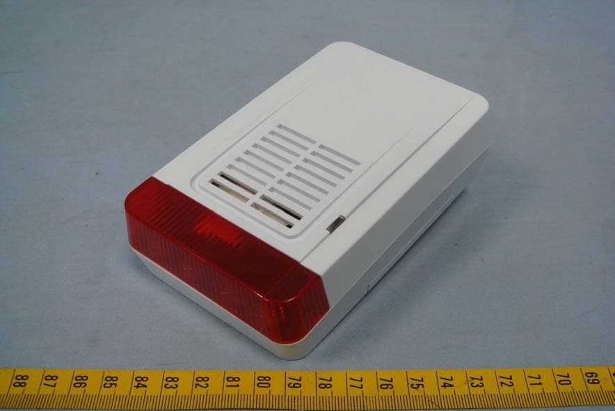
Click to zoom
Application Details
- Equipment Class
- DTS - Digital Transmission System
- Date of Grant
- Sep 24, 2012
- Application Purpose
- Original Equipment
- Date of Application
- Sep 24, 2012
- Equipment Note
- ZigBee Siren Repeater
- Frequency Range
- 2405.00000000 - 2480.00000000
- Company
- Sercomm Corporation
- Country
- Taiwan
Documents & Files
Document Text
Text extracted from the exhibit documents filed with the FCC. Open a document above to read the original.
Users Manual
SZ-SRN01 ZigBee Siren Repeater User Guide i Table of Contents CHAPTER 1 INTRODUCTION.............................................................................................. 1 Package Contents .............................................................................................................. 1 Specification ....................................................................................................................... 1 CHAPTER 2.............................................................................................................................. 2 DEVICE DESCRIPTION.......................................................................................................... 2 Components ....................................................................................................................... 2 Installation ......................................................................................................................... 3 Operation ........................................................................................................................... 3 REGULATORY APPROVAL.................................................................................................. 4 FCC Statement ..................................................................................................................4 CE Approval ..................................................................................錯誤! 尚未定義書籤。 Copyright 2012. All Rights Reserved. Document Version: 1.0 All trademarks and trade names are the properties of their respective owners. 1 Chapter 1 Introduction This Chapter provides an overview of the ZigBee Siren Repeater features and capabilities. Congratulations on the purchase of your new ZigBee Siren Repeater. The ZigBee Siren Repeater is a consumer electronic device, which is used for home automation and security. Package Contents The following items should be included: SZ-SRN01 x 1 pcs CR123A Lithium Battery x 1 pcs Screws for Wall mount x 1 pcs Quick installation guide x 1 pcs If any of the above items are damaged or missing, please contact your dealer imme- diately. Specification Frequency: 2.4GHz Battery type: DC 3V, CR123A Lithium Battery Power Source: AC110V Low Battery detection: under DC2.7V 85dB / 3 Meter piezo Siren. Operating temperature: 0° - 50°C (32° - 122°F); Storage temperature: -20° - 70°C (-4° - 158°F) LED indicator for Power and RF Tamper Alarm Dimensions : 129 mm x 80 mm x 43 mm (5.07" x 3.15" x 1.7") 1 2 Chapter 2 Device Description This Chapter provides device description for the ZigBee Siren Repeater Components Components Back Drawing Front Drawing 2 3 Installation 1. Remove the battery cover from siren. Observe correct polarity before insert batter- ies. Operation 1. Join Function For "Join" a network, please do the following instruction Press the Join/Leave button for less than 1 second. The LED is blinking while processing. If the sensor has been joined with the controller successfully, the Green LED will be on for 2 seconds and then off. The Green LED will be off instantly if failed. 2. Leave Function For "Leave" a network, please do the following instruction Press Join/Leave button for 3 seconds to let the sensor disassociate from the controller. The LED will stay off during the normal operation. The sensor is equipped with a tamper switch. If the cover of sensor is removed, the sensor will send an alarm to the ZigBee controller. The sensor will be in "Awake" mode before replacing the cover. 4 Chapter 3 REGULATORY APPROVAL FCC Statement This equipment has been tested and found to comply with the limits for a Class B digital device, pursuant to part 15 of the FCC rules. These limits are designed to provide reasonable protection against harmful interference in a residential installation. This equipment generates, uses and can radiate radio frequency energy and, if not installed and used in accordance with the instructions, may cause harmful interfer- ence to radio communications. However, there is no guarantee that interference will not occur in a particular installation. If this equipment does cause harmful interference to radio or television reception, which can be determined by turning the equipment off and on, the user is encouraged to try to correct the interference by one or more of the following measures: -Reorient or relocate the receiving antenna. -Increase the separation between the equipment and receiver. -Connect the equipment into an outlet on a circuit different from that to which the receiver is connected. -Consult the dealer or an experienced radio/TV technician for help. You are cautioned that changes or modifications not expressly approved by the party responsible for compliance could void your authority to operate the equipment. This device complies with Part 15 of the FCC Rules. Operation is subject to the follow- ing two conditions: (1) this device may not cause harmful interference and (2) this device must accept any interference received, including interference that may cause undesired operation This Transmitter must not be co-located or operating in conjunction with any other antenna or transmitter. This equipment complies with FCC RF radiation exposure limits set forth for an uncon- trolled environment . This equipment should be installed and operated with a minimum distance of 20 centimeters between the radiator and your body. 3
Users Manual
1 SZ-SRN01 ZigBee Siren Repeater Installation Guide Specification Frequency 2.4GHz Batter Type DC 3V, CR123A Lithium Battery Power Source 100 – 240VAC Operating Temperature 0 C to 50 C (32° - 122°F) Storage Temperature -20 C to 70 C (-4° - 158°F) Backup Battery Life Standy Mode 24 Hours RF Range Open Air:100M Internal Sounder Output At least 85 dB at 3 meters Dimension 129 mm x 80 mm x 43 mm (5.07" x 3.15" x 1.7") Package Contents Intallation Pre-Intallation 1. Remove the battery cover of the device. 2. Install the supplied CR123A battery correctly. Note: For safety reason, please replace the backup CR123A battery after the siren has been triggered (except self-testing). 2 Operation Power Status LED (Green/Amber) On (Green) - AC power mode. On (Amber) - DC battery mode. Blinking (Amber)- Low battery detection. 1. Join Function For "Join" a network, please do the following instruction: Put the ZigBee Coordinator into “Permit-Joining” mode. Press the Join/Leave button for less than 1 second. The Join/Leave LED is blinking while processing. If the siren has been joined with the ZigBee Coordinator successfully, the Join/Leave LED will be on for 2 seconds and then off. The Join/Leave LED will be off instantly if failed. 2. Leave Function For "Leave" a network, please do the following instruction: Press Join/Leave button for 3 seconds to let the siren disassociate from the ZigBee Coordinator. The Join/Leave LED will be on for 1 second and then off. 3. Test Function Remove the battery cover before testing. Press the Test button for 3 seconds. When pressing the Test button, the device will generate sounds and flash light to indicate that the siren is serviceable. 3 Note: The Join/Leave LED will stay off during the normal operation. The siren is equipped with a tamper switch. If the device is removed, the siren will send an alarm message to the ZigBee Coordinator. For safety reason, please replace the backup CR123A battery after the siren has been triggered (except self-testing). Procedure 1. Remove the screw of the outlet’s cover plate. Plug the device into the 110V outlet. Note: Make sure that the outlet is not controlled by a wall switch. 2. Tighten the device to the outlet with the supplied screw. The supplied washer can be used as a spacer between the screw and the outlet, if required. ZigBee Router Setup The siren can also be used as a ZigBee Router that lets you extend the security range of your home. When using the device as a ZigBee Router, just locate it in a suitable place, which has average signal strength and is at the halfway between the ZigBee Coordinator and the furthest sensor. The repeater can even boost signals weakened by walls and other obstructions. 4 FCC Statement This equipment has been tested and found to comply with the limits for a Class B digital device, pursuant to Part 15 of the FCC Rules. These limits are designed to provide reasonable protection against harmful interference in a residential installation. This equipment generates, uses and can radiate radio frequency energy and, if not installed and used in accordance with the instructions, may cause harmful interference to radio communications. However, there is no guarantee that interference will not occur in a particular installation. If this equipment does cause harmful interference to radio or television reception, which can be determined by turning the equipment off and on, the user is encouraged to try to correct the interference by one of the following measures: Reorient or relocate the receiving antenna. Increase the separation between the equipment and receiver. Connect the equipment into an outlet on a circuit different from that to which the receiver is connected. Consult the dealer or an experienced radio/TV technician for help. To assure continued compliance, any changes or modifications not expressly approved by the party responsible for compliance could void the user's authority to operate this equipment. (Example - use only shielded interface cables when connecting to computer or peripheral devices). FCC Radiation Exposure Statement This equipment complies with FCC RF radiation exposure limits set forth for an uncontrolled environment. This equipment should be installed and operated with a minimum distance of 20 centimeters between the radiator and your body. This device complies with Part 15 of the FCC Rules. Operation is subject to the following two conditions: (1) This device may not cause harmful interference, and (2) This device must accept any interference received, including interference that may cause undesired operation. This transmitter must not be co-located or operating in conjunction with any other antenna or transmitter.
Cover Letter(s)
SerComm Corporation中磊電子股份有限公司 Taipei Office: 8F, No.3-1, YuanQu St., NanKang, Taipei 115, Taiwan, R.O.C. TEL: 886-2-2655-3988 FAX: 886-2-2655-3966 Chu Nan Office: 3F, No. 81, YuYi Rd., Chu-Nan, Miao-Li 350, Taiwan, R.O.C. TEL: 886-37-585-899 FAX: 886-37-585-000 Date:August 24, 2012 BABT TCB Forsyth House, Churchfield Road, Walton-on-Thames, Surrey, KT12 2TD Confidentiality Request FCC ID: P27SZSRN01 Pursuant to Sections 0.457(d)(1)(ii) and 0.459 of the Commission’s Rules, SerComm Corporation hereby requests permanent confidential treatment of information accompanying this application as outlined below: Common exhibits for which confidentiality is requested are: Schematics Block Diagrams Theory of Operation The above materials contain trade secrets and proprietary information not customarily released to the public. The public disclosure of these matters might be harmful to the Applicant and provide unjustified benefits to its competitors. The Applicant understands that pursuant to Rule 0.457(d)(1)(ii), disclosure of this Application and all accompanying materials will not be made before the date of the Grant for this Application. Your Sincerely, Ronnie Cheng Associate Manager / R&D Division SerComm Corporation TEL: 886-2-2655-3988#2547 FAX: 886-2-2655-7379 E-Mail: [email protected]
Cover Letter(s)
SerComm Corporation中磊電子股份有限公司 Taipei Office: 8F, No.3-1, YuanQu St., NanKang, Taipei 115, Taiwan, R.O.C. TEL: 886-2-2655-3988 FAX: 886-2-2655-3966 Chu Nan Office: 3F, No. 81, YuYi Rd., Chu-Nan, Miao-Li 350, Taiwan, R.O.C. TEL: 886-37-585-899 FAX: 886-37-585-000 Date:August 24, 2012 BABT FCB Forsyth House, Churchfield Road, Walton-on-Thames, Surrey, KT12 2TD Dear Sir or Madam, We, SerComm Corporation hereby authorize Compliance Certification Services Inc / Stan Lin . to act as our agent in all matters relating to applications for equipment authorization, including the signing of all documents relating to these matters. This authorization expires on 2013/02/24 Your Sincerely, Ronnie Cheng Associate Manager / R&D Division SerComm Corporation TEL: 886-2-2655-3988#2547 FAX: 886-2-2655-7379 E-Mail: [email protected]
External Photos
Report No: T120815D07 Page 1 / 6 Rev.00 EXTERNAL PHOTOGRAPHS OF EUT
Internal Photos
Report No: T120815D07 Page 2 Rev.00 INTERNAL PHOTOGRAPHS OF EUT Report No: T120815D07 Page 3 Rev.00 Report No: T120815D07 Page 4 Rev.00 Antenna Report No: T120815D07 Page 5 Rev.00 Report No: T120815D07 Page 6 Rev.00
RF Exposure Info
Compliance Certification Services Inc. Report No.: T120815D07-RP1 FCC ID: P27SZSRN01 Date of Issue: Sep. 14, 2012 Page 44 Rev.00 This report shall not be reproduced except in full, without the written approval of Compliance Certification Services. 8. APPENDIX I RADIO FREQUENCY EXPOSURE LIMIT According to §15.247(i), systems operating under the provisions of this section shall be operated in a manner that ensures that the public is not exposed to radio frequency energy levels in excess of the Commission's guidelines. See § 1.1307(b)(1) of this chapter. EUT Specification EUT ZigBee Siren Repeater Frequency band (Operating) WLAN: 2.412GHz ~ 2.462GHz WLAN: 5.18GHz ~ 5.32GHz / 5.50GHz ~ 5.70GHz WLAN: 5.745GHz ~ 5.825GHz Others 2405 MHz ~ 2480 MHz Device category Portable (<20cm separation) Mobile (>20cm separation) Others Exposure classification Occupational/Controlled exposure (S = 5mW/cm 2 ) General Population/Uncontrolled exposure (S=1mW/cm 2 ) Antenna diversity Single antenna Multiple antennas Tx diversity Rx diversity Tx/Rx diversity Max. output power 21.37dBm (0.1371W) Antenna gain (Max) 2.87 dBi (including cable loss) (Numeric gain: 1.94) Evaluation applied MPE Evaluation SAR Evaluation N/A Remark: 1. The maximum output power is 21.37dBm ( 0.1371W) at 2440MHz (with 1.94 numeric antenna gain.) 2. For mobile or fixed location transmitters, no SAR consideration applied. The maximum power density is 1.0 mW/cm 2 even if the calculation indicates that the power density would be larger. TEST RESULTS No non-compliance noted. Compliance Certification Services Inc. Report No.: T120815D07-RP1 FCC ID: P27SZSRN01 Date of Issue: Sep. 14, 2012 Page 45 Rev.00 This report shall not be reproduced except in full, without the written approval of Compliance Certification Services. Calculation Given d GP E ×× = 30 & 3770 2 E S= Where E = Field strength in Volts / meter P = Power in Watts G = Numeric antenna gain d = Distance in meters S = Power density in milliwatts / square centimeter Combining equations and re-arranging the terms to express the distance as a function of the remaining variables yields: 2 3770 30 d GP S ×× = Changing to units of mW and cm, using: P (mW) = P (W) / 1000 and d (cm) = d(m) / 100 Yields () () 2 2 0796.0 100/3770 1000/30 d GP d GP S × ×= × ×× = Equation 1 Where d = Distance in cm P = Power in mW G = Numeric antenna gain S = Power density in mW / cm 2 Maximum Permissible Exposure EUT output power = 137.088mW Numeric Antenna gain = 1.94 Substituting the MPE safe distance using d = 20 cm into Equation 1: Yields GPS××=000199.0 Where P = Power in mW G = Numeric antenna gain S = Power density in mW / cm 2 Æ Power density = 0. 0529 mW / cm 2 (For mobile or fixed location transmitters, the maximum power density is 1.0 mW/cm 2 even if the calculation indicates that the power density would be larger.)
Test Report
Compliance Certification Services Inc. Report No.: T120815D07-RP1 FCC ID: P27SZSRN01 Date of Issue: Sep. 14, 2012 Page 1 / 49 Rev.00 FCC 47 CFR PART 15 SUBPART C TEST REPORT For ZigBee Siren Repeater Model: SZ-SRN01xxxxxxxx (x= 0~9, A~Z, Blank or any Character) Trade Name: SerComm Issued to SerComm Corporation 8F, No. 3-1, YuanQu St., NanKang, Taipei 115, Taiwan, R.O.C. Issued by Compliance Certification Services Inc. No.81-1, Lane 210, Bade 2nd Rd., Lujhu Township, Taoyuan County 33841, Taiwan, R.O.C. TEL: 886-3-324-0332 FAX: 886-3-324-5235 http://www.ccsrf.com [email protected] Note: This report shall not be reproduced except in full, without the written approval of Compliance Certification Services Inc. This document may be altered or revised by Compliance Certification Services Inc. personnel only, and shall be noted in the revision section of the document. The client should not use it to claim product endorsement by TAF, A2LA, NIST or any government agencies. The test results in the report only apply to the tested sample. Compliance Certification Services Inc. Report No.: T120815D07-RP1 FCC ID: P27SZSRN01 Date of Issue: Sep. 14, 2012 Page 2 Rev.00 This report shall not be reproduced except in full, without the written approval of Compliance Certification Services. Revision History Rev. Issue Date Revisions Effect Page Revised By 00 Sep. 14, 20012 Initial Issue ALL Jill Shiau Compliance Certification Services Inc. Report No.: T120815D07-RP1 FCC ID: P27SZSRN01 Date of Issue: Sep. 14, 2012 Page 3 Rev.00 This report shall not be reproduced except in full, without the written approval of Compliance Certification Services. TABLE OF CONTENTS 1. TEST RESULT CERTIFICATION ...........................................................................................4 2. EUT DESCRIPTION................................................................................................................5 3. TEST METHODOLOGY..........................................................................................................6 3.1 EUT CONFIGURATION .....................................................................................................6 3.2 EUT EXERCISE .................................................................................................................6 3.3 GENERAL TEST PROCEDURES......................................................................................6 3.4 FCC PART 15.205 RESTRICTED BANDS OF OPERATIONS ..........................................7 3.5 DESCRIPTION OF TEST MODES.....................................................................................7 4. INSTRUMENT CALIBRATION ...............................................................................................8 4.1 MEASURING INSTRUMENT CALIBRATION ....................................................................8 4.2 MEASUREMENT EQUIPMENT USED ..............................................................................8 4.3 MEASUREMENT UNCERTAINTY.....................................................................................9 5. FACILITIES AND ACCREDITATIONS .................................................................................10 5.1 FACILTIES .......................................................................................................................10 5.2 EQUIPMENT....................................................................................................................10 5.3 TABLE OF ACCREDITATIONS AND LISTINGS..............................................................11 6. SETUP OF EQUIPMENT UNDER TEST ..............................................................................12 6.1 SETUP CONFIGURATION OF EUT ................................................................................12 6.2 SUPPORT EQUIPMENT..................................................................................................12 7. FCC PART 15.247 REQUIREMENTS ..................................................................................13 7.1 6DB BANDWIDTH ............................................................................................................13 7.2 PEAK POWER .................................................................................................................16 7.3 AVERAGE POWER .........................................................................................................19 7.4 BAND EDGES MEASUREMENT .....................................................................................22 7.5 PEAK POWER SPECTRAL DENSITY .............................................................................27 7.6 SPURIOUS EMISSIONS..................................................................................................30 7.7 POWERLINE CONDUCTED EMISSIONS .......................................................................41 8. APPENDIX I RADIO FREQUENCY EXPOSURE .................................................................44 9. APPENDIX II PHOTOGRAPHS OF TEST SETUP...............................................................46 Compliance Certification Services Inc. Report No.: T120815D07-RP1 FCC ID: P27SZSRN01 Date of Issue: Sep. 14, 2012 Page 4 Rev.00 This report shall not be reproduced except in full, without the written approval of Compliance Certification Services. 1. TEST RESULT CERTIFICATION Applicant: SerComm Corporation 8F, No. 3-1, YuanQu St., NanKang, Taipei 115, Taiwan, R.O.C. Manufacturer: SerComm Corporation 8F, No. 3-1, YuanQu St., NanKang, Taipei 115, Taiwan, R.O.C. Equipment Under Test: ZigBee Siren Repeater Trade Name: SerComm Model: SZ-SRN01xxxxxxxx (x= 0~9, A~Z, Blank or any Character) Date of Test: August 20 ~ September 12, 2012 APPLICABLE STANDARDS STANDARD TEST RESULT FCC 47 CFR Part 15 Subpart C No non-compliance noted We hereby certify that: The above equipment was tested by Compliance Certification Services Inc. The test data, data evaluation, test procedures, and equipment configurat…
Text truncated - open the document above for the full version.
Test Setup Photos
Compliance Certification Services Inc. Report No.: T120815D07-RP1 FCC ID: P27SZSRN01 Date of Issue: Sep. 14, 2012 Page 46 Rev.00 This report shall not be reproduced except in full, without the written approval of Compliance Certification Services. 9. APPENDIX II PHOTOGRAPHS OF TEST SETUP Radiated Emission Set up Photos Below 1GHz Compliance Certification Services Inc. Report No.: T120815D07-RP1 FCC ID: P27SZSRN01 Date of Issue: Sep. 14, 2012 Page 47 Rev.00 This report shall not be reproduced except in full, without the written approval of Compliance Certification Services. Above 1GHz Compliance Certification Services Inc. Report No.: T120815D07-RP1 FCC ID: P27SZSRN01 Date of Issue: Sep. 14, 2012 Page 48 Rev.00 This report shall not be reproduced except in full, without the written approval of Compliance Certification Services. Conducted Emission Setup Photos Compliance Certification Services Inc. Report No.: T120815D07-RP1 FCC ID: P27SZSRN01 Date of Issue: Sep. 14, 2012 Page 49 Rev.00 This report shall not be reproduced except in full, without the written approval of Compliance Certification Services. Power Line Conducted Emissions Setup Photos
Contact Information
Applicant
Nick Wu(Engineer)
Test Firm
Compliance Certification Services Inc.Kurt Chen
Technical Specifications
| # | Rule Parts | Frequency Range | Power Output |
|---|---|---|---|
| 1 | 15C | 2.40 GHz - 2.48 GHz | 140.00 mW |
Other Applications from Sercomm Corporation
P27-MOTIONZW60R0
Aug 04, 2026WIRELESS PIR MOTION SENSOR
Equipment Class
DTS - Digital Transmission SystemP27-SCP5173P
Dec 24, 2025Moso Canopy 5GOD2
Equipment Class
CBD - Citizens Band Category A and B DevicesP27-TPM530
Nov 24, 2025CATM1 Module
Equipment Class
PCB - PCS Licensed TransmitterP27MQIO
Sep 16, 2025Mqio 9W
Equipment Class
DTS - Digital Transmission SystemP27LORAAREAV2
Jul 25, 2024MachineQ Area 8C V2 LoRaWAN Gateway
Equipment Class
PCB - PCS Licensed Transmitter