P4A0005-8327-53OmniRemote Plus Springboard Module
Pacific Neo-Tek, Inc.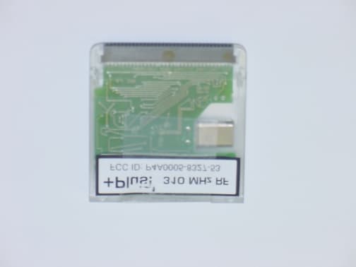
Click to zoom
Application Details
- Equipment Class
- DSC - Part 15 Security/Remote Control Transmitter
- Date of Grant
- Jun 23, 2002
- Application Purpose
- Original Equipment
- Date of Application
- Jun 23, 2002
- Equipment Note
- OmniRemote Plus Springboard Module
- Frequency Range
- 310.00000000 - 310.00000000
- Company
- Pacific Neo-Tek, Inc.
- Country
- United States
Documents & Files
Document Text
Text extracted from the exhibit documents filed with the FCC. Open a document above to read the original.
Users Manual
- Table of contents FCC Statements 1: Quick start 2: Avoiding problems 3: Basic features in detail 4: X-10 5: Macros 6: Timers 7: Support contact FCC Statements This device complies with Part 15 of the FCC Rules. Operation is subject to the following two conditions: (1) this device may not cause harmful interference, and (2) this device must accept any interference received, including interference that may cause undesired operation. WARNING: Changes or modifications to this unit not expressly approved by the party responsible for compliance could void the user's authority to operate the equipment. NOTE: This equipment has been tested and found to comply with the limits for a Class B digital device, pursuant to Part 15 of the FCC Rules. These limits are designed to provide reasonable protection against harmful interference in a residential installation. This equipment generates, uses, and can radiate radio frequency energy and, if not installed and used in accordance with the instructions, may cause harmful interference to radio communications. However, there is no guarantee that interference will not occur in a particular installation. If this equipment does cause harmful interference to radio or television reception, which can be determined by turning the equipment off and on, the user is encouraged to try to correct the interference by one or more of the following measures: -Reorient or relocate the receiving antenna. -Increase the separation between the equipment and receiver. -Connect the equipment into an outlet on a circuit different from that to which the receiver is connected. -Consult the dealer or an experienced radio TV technician for help. - Chapter 1:Quick start What is it? OmniRemote is an IR learning remote control. It uses infrared light to communicate with TV's, VCR's and many other devices (nearly any device that uses IR). OmniRemote Plus can also control RF X-10 using a built in radio transmitter. "Out of the box" this software won't control anything. Because it's a learning remote control it requires a training period before it can be used. What this method loses in convenience it gains in flexibility. Once the buttons have been created (you can use OmniRemote's existing buttons or you can create new ones all your own) you can train them using Menu|Modes|Training (menus pop up either by clicking the Menu silk button or by tapping the bar at the top of the screen). While in training mode, align your remote (explained in detail in chapter 2), double click the button you want to train, then press the equivalent button on your remote control. For buttons that can be held down during use (for example volume buttons or some fast-forward and rewind buttons) hold the button until the Learn IR screen disappears rather than quickly pressing and releasing the button. Continue doing this until every button has been trained, then choose Menu|Modes|Normal. You can tell which buttons need to be trained because untrained normal buttons are displayed with a "dotty" grey border. After that you're ready to go! - Chapter 2:Avoiding problems If you have poor range, or if buttons work intermittently or not at all try the following steps: Try re-training the button you are having trouble with. Use: Menu|Buttons|Edit|choose button|Retrain or use the training mode. It is unlikely that you will train every button perfectly the first time. Some buttons will probably require re-training. Try a different IR carrier frequency. This setting is in Menu|Options|Training Settings it is used during training. Once the optimum setting is determined, it should be used for all buttons on that remote. To determine the optimum setting, perform the following steps: Press the Auto detect button. Hold your remote up to the IR sensor on your Palm or your OmniRemote Module. Hold down or repeatedly press one of your remote's buttons. On the screen the word Testing should be followed by changing numbers as it scans for the correct frequency. Very slowly pull your remote away from the Visor until slow beeping begins. Hold remote still and continue holding or pressing button while beeps continue. Test will complete in a few seconds. Auto detect will only try scanning the lower five built-in frequencies and the one typed on the blank (under the Auto detect button). 39.2 is the most commonly used frequency. Try fast sampling mode. This setting is also in Menu|Options|Training Settings. For some devices it can yield much better reliability, but its shorter sample length won't work with all devices. Also buttons trained with this setting only work with the Springboard Module installed. (so you can't share with your friends without Visors) When training try holding the button on your remote a little longer rather than just a "tap". Training must be performed with the remote aimed at the IR receiver on the left side of the Visor near the top. When training, try positioning the Visor and remote a different distance apart. Generally closer is better, but on some remotes the LED is not in the middle, if it's near the side and you make the Visor's receiver touch the middle of the remote, you might miss it entirely, in which case a half inch apart might be better. Make sure the remote's LED and the Visor's receiver are at the same height and sitting on a stable surface (rather than in your hand). The beeps in training mode are helpful as a guide, but aren't a guarantee that you have them aligned perfectly. When testing, hold the Visor near the device you are trying to control, but not within six inches. Keep the Visor aimed at the device's receiver and don't sit at an angle to the front of the device. Glass doors or other obstacles between the Palm and the device can cause poor range. If using timers, make sure OmniRemote is running when the timer goes off, or if the Visor is off that OmniRemote was the program running when it was turned off. - Chapter 3:Basic features in detail This chapter assumes that you hav…
Text truncated - open the document above for the full version.
Block Diagram
FCC ID: P4A0005-8327-53
External Photos
External Photos FCC ID: P4A0005-8327-53
ID Label/Location Info
Label artwork Label location
Internal Photos
Internal Photos FCC ID: P4A0005-8327-53
Operational Description
Page 1 of 2. Pacific Neo-Tek Making the impossible possible The OmniRemote Plus Springboard Module was designed and manufactured by: Pacific Neo-Tek, Inc. 2-1500 E Cliff Dr. #B Santa Cruz, CA 95062 The OmniRemote Plus Springboard Module contains a 310MHz RF transmitter which is designed to send data to standard “off the shelf” X-10 compatible RF receivers (produced by various other manufacturers). The purpose of this is to allow the user to control lights and appliances (through an X-10 home control system) from their Handspring Visor handheld organizer. A Springboard Module is an expansion card which slides into a Handspring Visor handheld organizer giving it additional software and capabilities (in this case including the RF transmitter). The transmitter is a simple 310MHz sine wave oscillator (L-C oscillator) which is turned on and off under the control of software running on the Visor Handheld producing a pulsed CW signal. The timing of these pulses of 310MHz RF describe the binary data which is being sent to the X-10 receiver. The L-C oscillator can be turned on and off under software control because its source of power is one of the logic outputs of one of the I/O chips in the module. A logic 1 being output from this general purpose I/O pin will supply 3.2 volts which is enough to power the oscillator. The transmitter circuit uses very little current, so no amplification is needed. The antenna is internal and consists of a track on the PCB which forms an elongated loop. www.pacificneotek.c om Page 2 of 2. Schematic of RF transmitter portion of design Board layout of RF transmitter portion of design Contact: Name: Charlie Payne Phone: (831)476-3236 Fax: (831)475-5380 E-mail: [email protected]
Schematics
FCC ID: P4A0005-8327-53 Schematic of RF transmitter portion of design Board layout of RF transmitter portion of design
Test Report
Test Report FCC Part 15.231 RSS 210 for Pacific Neo-Tek on the Omni Remote Spring Board Module Model: OSB4 FCC ID: P4A0005-8327-53 Test Report #: 20540461 Date of Report: June 6, 2002 Job #: J20054046 Date of Test: July 2, 3 & 5, 2001 Total No of Pages Contained in this Report: 19 NVLAP Laboratory Code: 200201-0 Marcos Rodriguez, Test Engineer Ollie Moyrong, EMC Manager Review Date: ___________ All services undertaken are subject to the following general policy: Reports are submitted for exclusive use of the client to whom they are addressed. Their significance is subject to the adequacy and representative character of the samples and to the comprehensiveness of the tests, examinations or surveys made. This report shall not be reproduced except in full, without written consent of Intertek Testing Services, NA Inc. This report must not be used to claim product endorsement by NVLAP, NIST or any other agency of the U.S. Government. FCC Part 15.231/RSS210 Cert, Ver 2/3/97 1365 Adams Court Menlo Park, CA 94025 Pacific Neo-Tek, Model No. OSB4Date of Test: July 2, 3 & 5, 2001 FCC ID: P4A0005-8327-53 Report No.: 20540461Page 1 of 19 TABLE OF CONTENTS 1.0Summary of Tests.............................................................................................................2 2.0General Description ........................................................................................................3 2.1Product Description...............................................................................................3 2.2Related Submittal(s) Grants...................................................................................4 2.3Test Methodology..................................................................................................5 2.4Test Facility...........................................................................................................5 3.0System Test Configuration..............................................................................................6 3.1Support Equipment ................................................................................................6 3.2Block Diagram of Test Setup.................................................................................6 3.3Justification............................................................................................................7 3.4Software Exercise Program ...................................................................................7 3.5Mode of Operation during Test .............................................................................7 3.6Modifications Required for Compliance ...............................................................7 4.0Measurement Results ......................................................................................................8 4.1Radiated emission..................................................................................................8 4.1.1 Field Strength Calculation .........................................................................8 4.1.2 Radiated Emission test results ...................................................................9 4.2AC Line Conducted Emission test results ...........................................................11 4.3Occupied Bandwidth ...........................................................................................12 4.4Transmitter Duty Cycle Calculation and Measurements.....................................14 5.0Antenna Requirement ...................................................................................................18 6.0 List of Test Equipment ..................................................................................................19 1365 Adams Court Menlo Park, CA 94025 Pacific Neo-Tek, Model No. OSB4Date of Test: July 2, 3 & 5, 2001 FCC ID: P4A0005-8327-53 Report No.: 20540461Page 2 of 19 1.0Summary of Tests MODEL: OSB4 FCC ID: P4A0005-8327-53 TESTREFERENCERESULTSREPORT SECTION Field Strength of fundamental15.231(b)Complies4.1 Field Strength of spurious emissions15.231(b)Complies4.1 Field Strength of emissions in restricted bands15.231(b), 15.205Complies4.1 AC Conducted Emission15.207Not Applicable- 20 dB Bandwidth15.231(c)Complies4.3 Periodic Operation Requirement15.231(a)Complies4.4 Frequency Tolerance15.231(d)Not Applicable- Antenna Requirement15.203Complies5.0 1365 Adams Court Menlo Park, CA 94025 Pacific Neo-Tek, Model No. OSB4Date of Test: July 2, 3 & 5, 2001 FCC ID: P4A0005-8327-53 Report No.: 20540461Page 3 of 19 2.0General Description 2.1Product Description Overview of the EUT ApplicantPacific Neo-Tek 2-1500 East Cliff Drive Suite B, Santa Cruz, CA 95062, USA Trade Name & Model No.Pacific Neo –Tek, OSB4 FCC IdentifierP4A0005-8327-53 Use of product This is an expansion module which can be installed in an “off the shelf” handled organized (Handling Visor). The module mimics the RF signal w hich w ould be generated by an X-10 hand held remote, thus allow ing the user to control their X-10 devices with their Visor hand held organizer. Transmitter activation[ X ] Manual and automatically deactivate within 5 seconds of being released [ ] Periodic transmissions Frequency Range310 MHz Antenna RequirementThe EUT uses a permanently connected antenna. Manufacturer name & addressPacific Neo-Tek 2-1500 East Cliff Drive Suite B, Santa Cruz, CA 95062, USA 1365 Adams Court Menlo Park, CA 94025 Pacific Neo-Tek, Model No. OSB4Date of Test: July 2, 3 & 5, 2001 FCC ID: P4A0005-8327-53 Report No.: 20540461Page 4 of 19 2.2Related Submittal(s) Grants This is an Application for Certification of a low power transmitter. One transmitter is included in this Application. 1365 Adams Court Menlo Park, CA 94025 Pacific Neo-Tek, Model No. OSB4Date of Test: July 2, 3 & 5, 2001 FCC ID: P4A0005-8327-53 Report No.: 20540461Page 5 of 19 2.3Test Methodology Both AC mains line-conducted and radiated emissions measurements were performed according to the procedures in ANSI C63.…
Text truncated - open the document above for the full version.
Test Setup Photos
FCC ID: P4A0005-8327-53 FCC ID: P4A0005-8327-53
Contact Information
Applicant
Lorie Hull(Manager)
Technical Contact
Intertek Testing ServicesDavid Chernomordik
[email protected]650 463 2900
1365 Adams Court · Menlo Park, California · United States
Non-Technical Contact
Intertek Testing ServicesDavid Chernomordik
[email protected]650 463 2900
Test Firm
Intertek Testing Services NA Inc.John Quigley
Technical Specifications
| # | Rule Parts | Frequency Range | Power Output |
|---|---|---|---|
| 1 | 15.231 | 310 MHz - 310 MHz | - |