P4Q-N448Watch
Mitac Digital Technology Corporation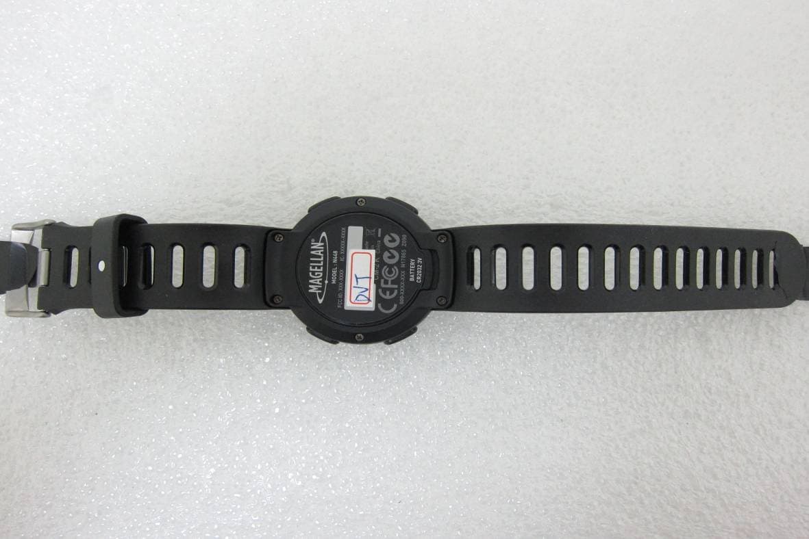
Click to zoom
Application Details
- Equipment Class
- DTS - Digital Transmission System
- Date of Grant
- Aug 25, 2013
- Application Purpose
- Original Equipment
- Date of Application
- Aug 22, 2013
- Equipment Note
- Watch
- Frequency Range
- 2402.00000000 - 2480.00000000
- Country
- Taiwan
Documents & Files
Document Text
Text extracted from the exhibit documents filed with the FCC. Open a document above to read the original.
Users Manual
Echo Series User Manual 1 Use only Magellan cables and accessories; the use of non- Magellan cables and accessories (other than compatible ANT+ wireless accessories) may severely degrade performance or damage the device, and will void the warranty. Lithium-ion battery: Never store the device or the battery in a high temperature location. Do not disassemble, puncture or incinerate the battery. Do not attempt to remove the battery. Please contact Magellan Technical Center for issues related to the battery. Do not use the device outside of the following temperature range: -4°F to 131°F (-20°C to 55°C). The information provided in this document is subject to change without notice. Improvements and enhancements to the product may occur without any formal notification. Check the Magellan website (active.magellanGPS.com/start) for product updates and additional information. The IEC 60529/IPX7 is a European system of test specification standards for classifying the degrees of protection provided by the Safety It is strongly recommended to consult a doctor before starting any exercise program. If you have a pacemaker or other implemented device, consult your doctor before using the heart rate monitor. 2 enclosures of electrical equipment. An IPX7 designation means that the unit withstands immersion in one meter (approx 3ft) of still water for up to 30 minutes. Magellan guarantees this grade provided the battery door and all jack covers are properly and securely closed. This device is not IPX8 grade; water-pressure such as washing the unit with running water may cause damage to the unit and voids warranty. Declaration of conformity Note: For regulatory identification purposes, Echo is assigned a model number of N448. CE Products with the CE marking comply with Radio & Telecommunication Terminal Equipment Directive (R&TTE) (1999/5/EC), the Electromagnetic Compatibility Directive (2004/108/EC) and the Low Voltage Directive (2006/95/EC) - issued by the Commission of the European Community. Compliance with these directives implies conformity to the following European Standards: EN301489-1: Electronic compatibility and Radio spectrum Matters (ERM), ElectroMagnetic Compatibility (EMC) standard for radio equipment and services; Part 1: Common technical requirements EN301489-17: Electronic compatibility and Radio spectrum Matters (ERM),ElectroMagnetic Compatibility (EMC) standard for radio equipment and services; Part 17: Specific conditions for 2,4 GHz wideband transmission systems and 3 5 GHz high performance RLAN equipment EN 300 328: Electromagnetic compatibility and Radio spectrum Matters (ERM); Wideband Transmission systems; Data transmission equipment operating in the 2,4 GHz ISM band and using spread spectrum modulation techniques; Harmonized EN covering essential requirements under article 3.2 of the R&TTE Directive EN55022: Radio disturbance characteristics EN55024: Immunity characteristics EN61000-3-2: Limits for harmonic current emissions EN61000-3-3: Limitation of voltage fluctuation and flicker in low-voltage supply system IEC 60950-1:2001: Product Safety The manufacturer cannot be held responsible for modifications made by the User and the consequences thereof, which may alter the conformity of the product with the CE Marking. Hereby, Masternaut declares that this N382 is in compliance with the essential requirements and other relevant provisions of Directive 1999/5/EC. WEEE This product must not be disposed of as normal household waste, in accordance with the EU directive for waste electrical and electronic equipment (WEEE - 2002/96/EC). Instead, it should be disposed of by returning it to the point of sale, or to a municipal recycling collection point. 4 FCC Federal Communications Commission (FCC) Statement You are cautioned that changes or modifications not expressly approved by the part responsible for compliance could void the user’s authority to operate the equipment. This equipment has been tested and found to comply with the limits for a Class B digital device, pursuant to part 15 of the FCC rules. These limits are designed to provide reasonable protection against harmful interference in a residential installation. This equipment generates, uses and can radiate radio frequency energy and, if not installed and used in accordance with the instructions, may cause harmful interference to radio communications. However, there is no guarantee that interference will not occur in a particular installation. If this equipment does cause harmful interference to radio or television reception, which can be determined by turning the equipment off and on, the user is encouraged to try to correct the interference by one or more of the following measures: • Reorient or relocate the receiving antenna. • Increase the separation between the equipment and receiver. • Connect the equipment into an outlet on a circuit different from that to which the receiver is connected. • Consult the dealer or an experienced radio/TV technician for help. This device complies with Part 15 of the FCC Rules. Operation is subject to the following two conditions: (1) this device may not cause harmful interference and (2) this device must accept any interference received, including interference that may cause undesired operation You are cautioned that changes or modifications not expressly approved by the party responsible for compliance could void your authority to operate the equipment. FCC RF Radiation Exposure Statement 5 This transmitter must not be co-location or operating in conjunction with any other antenna or transmitter. This equipment complies with FCC RF radiation exposure limits set forth for an uncontrolled environment. This equipment should be installed and operated with a minimum distance of 20 centimeters between the radiator and your body. IC This Class B digital apparatus complies with Canada ICES-003. Cet appareil numérique de la classe B est conforme à la norme NMB-003 du Canada. Operation is subject to …
Text truncated - open the document above for the full version.
Cover Letter(s)
UNLESS OTHER SPECIFIED TOLERANCES ON: X=± X.X=± X.XX= ANGLES=± HOLEDIA=± INPAQ TECHNOLOGY CO., LTD. SCALE: ----- UNIT:mm DRAWN BY:楊奇峰 CHECKED BY:蔡孟學 DESIGNED BY:謝立庭 APPROVED BY:黃月碧 THIS DRAWINGS AND SPECIFICATIONS ARE THE PROPERTY OF INPAQ TECHNOLOGY CO.,LTD.AND SHALL NOT BE REPRODUCED OR USED AS THE BASIS FOR THE MANUFACTURE OR SALE OF APPARATUS OR DEVICES WITHOUT PERMISSION DOCUMENT SPEC REV. TITLE:ACA-2012-A1-CC-S Specification NO. ENS000030640 A1 PAGE 1 OF 7 - ACA-2012-A1-CC-S Specification 1. APPLICATION: WLAN, 802.11b/g, Bluetooth, etc... 2. Explanation of Part Number : AC A 2012 A1 CCS (1) (2) _ (3) _ (4) _ (5) _ (6) (7) (1) Product Type:Chip Antenna (2) Center Frequency/Band Code : A—2442MHz group (3) Size Code: 2.0mm(Length) x 1.2mm(Width) (4) Design Revision Code: Rev.1 (5) CC= Coupling Ceramic Type (6) Special Code: S=RoHS Compliant (7) Suffix For Special Requirements 3. Electrical Specification : ITEM SPECIFICATION Frequency Band 2400MHz~2483MHz VSWR Less than 3 Polarization Linear *Peak Gain 1.72 dBi Typ. *Peak Efficiency 72.3% Typ. Impedance 50Ω Typ. * Test condition: Test board size 110*55 mm Matching circuit: Pi matching circuit will be required 4. Physical Dimension : (Unit:mm) Chip Antenna L W H A ACA2012 2.0±0.31.2±0.30.55±0.20.4±0.25 UNLESS OTHER SPECIFIED TOLERANCES ON: X=± X.X=± X.XX= ANGLES=± HOLEDIA=± INPAQ TECHNOLOGY CO., LTD. SCALE: ----- UNIT:mm DRAWN BY:楊奇峰 CHECKED BY:蔡孟學 DESIGNED BY:謝立庭 APPROVED BY:黃月碧 THIS DRAWINGS AND SPECIFICATIONS ARE THE PROPERTY OF INPAQ TECHNOLOGY CO.,LTD.AND SHALL NOT BE REPRODUCED OR USED AS THE BASIS FOR THE MANUFACTURE OR SALE OF APPARATUS OR DEVICES WITHOUT PERMISSION DOCUMENT SPEC REV. TITLE:ACA-2012-A1-CC-S Specification NO. ENS000030640 A1 PAGE 2 OF 7 - 5. Recommend PCB Layout : (Unit:mm) *Clearance Area = 8 x 2.5 mm All metallization should be removed from all PCB layers. UNLESS OTHER SPECIFIED TOLERANCES ON: X=± X.X=± X.XX= ANGLES=± HOLEDIA=± INPAQ TECHNOLOGY CO., LTD. SCALE: ----- UNIT:mm DRAWN BY:楊奇峰 CHECKED BY:蔡孟學 DESIGNED BY:謝立庭 APPROVED BY:黃月碧 THIS DRAWINGS AND SPECIFICATIONS ARE THE PROPERTY OF INPAQ TECHNOLOGY CO.,LTD.AND SHALL NOT BE REPRODUCED OR USED AS THE BASIS FOR THE MANUFACTURE OR SALE OF APPARATUS OR DEVICES WITHOUT PERMISSION DOCUMENT SPEC REV. TITLE:ACA-2012-A1-CC-S Specification NO. ENS000030640 A1 PAGE 3 OF 7 - 6. Electrical Characteristics : VSWR Radiation Pattern The Gain pattern is measured in INPAQ’s FAR-field chamber. DUT is placed on the table of rotator, a standard horn antenna and Vector Network Analyzer is used to collect data. ◎ 3D Gain Pattern (2442 MHz) Mark Frequency VSWR 1 2400 MHz1.80 2 2442 MHz1.53 3 2483 MHz2.28 3D Chamber Definition Power (dBm) -30 5 -25 -20 -15 -10 -5 0 Z Y X Azimuth = 100.0 El e va ti on = -30. 0 Roll = -70.0 X Y Z UNLESS OTHER SPECIFIED TOLERANCES ON: X=± X.X=± X.XX= ANGLES=± HOLEDIA=± INPAQ TECHNOLOGY CO., LTD. SCALE: ----- UNIT:mm DRAWN BY:楊奇峰 CHECKED BY:蔡孟學 DESIGNED BY:謝立庭 APPROVED BY:黃月碧 THIS DRAWINGS AND SPECIFICATIONS ARE THE PROPERTY OF INPAQ TECHNOLOGY CO.,LTD.AND SHALL NOT BE REPRODUCED OR USED AS THE BASIS FOR THE MANUFACTURE OR SALE OF APPARATUS OR DEVICES WITHOUT PERMISSION DOCUMENT SPEC REV. TITLE:ACA-2012-A1-CC-S Specification NO. ENS000030640 A1 PAGE 4 OF 7 - ◎ 2D Gain Pattern (2442 MHz) X-Y Plane Y-Z Plane X-Z Plane X Z Y Z X Y UNLESS OTHER SPECIFIED TOLERANCES ON: X=± X.X=± X.XX= ANGLES=± HOLEDIA=± INPAQ TECHNOLOGY CO., LTD. SCALE: ----- UNIT:mm DRAWN BY:楊奇峰 CHECKED BY:蔡孟學 DESIGNED BY:謝立庭 APPROVED BY:黃月碧 THIS DRAWINGS AND SPECIFICATIONS ARE THE PROPERTY OF INPAQ TECHNOLOGY CO.,LTD.AND SHALL NOT BE REPRODUCED OR USED AS THE BASIS FOR THE MANUFACTURE OR SALE OF APPARATUS OR DEVICES WITHOUT PERMISSION DOCUMENT SPEC REV. TITLE:ACA-2012-A1-CC-S Specification NO. ENS000030640 A1 PAGE 5 OF 7 - 7. Environmental Characteristics (1) Reliability Test Item Condition Specification Thermal shock 1. 30±3 minutes at -40°C±5°C, 2. Convert to +105°C (5 minutes) 3. 30±3 minutes at +105°C±5°C, 4. Convert to -40°C (5 minutes) 5. Total 100 continuous cycles No apparent damage Fulfill the electrical spec. after test. Humidity resistance 1. Humidity: 85% R.H. 2. Temperature: 85±5°C 3. Time: 1000 hours. No apparent damage Fulfill the electrical spec. after test. High temperature resistance 1. Temperature: 150°C±5°C 2. Time: 1000 hours. No apparent damage Fulfill the electrical spec. after test. Low temperature resistance 1. Temperature: -40°C±5°C 2. Time: 1000 hours. No apparent damage Fulfill the electrical spec. after test. Soldering heat resistance 1. Solder bath temperature : 260±5°C 2. Bathing time: 10±1 seconds No apparent damage Solderability The dipped surface of the terminal shall be at least 95% covered with solder after dipped in solder bath of 245±5°C for 3±1 seconds. No apparent damage (2) Storage Condition (a) At warehouse: The temperature should be within 0 ~ 30°C and humidity should be less than 60% RH. The product should be used within 1 year from the time of delivery. (b) On board: The temperature should be within -40~85°C and humidity should be less than 85% RH. (3) Operating Temperature Range Operating temperature range : -40°C to +105°C. UNLESS OTHER SPECIFIED TOLERANCES ON: X=± X.X=± X.XX= ANGLES=± HOLEDIA=± INPAQ TECHNOLOGY CO., LTD. SCALE: ----- UNIT:mm DRAWN BY:楊奇峰 CHECKED BY:蔡孟學 DESIGNED BY:謝立庭 APPROVED BY:黃月碧 THIS DRAWINGS AND SPECIFICATIONS ARE THE PROPERTY OF INPAQ TECHNOLOGY CO.,LTD.AND SHALL NOT BE REPRODUCED OR USED AS THE BASIS FOR THE MANUFACTURE OR SALE OF APPARATUS OR DEVICES WITHOUT PERMISSION DOCUMENT SPEC REV. TITLE:ACA-2012-A1-CC-S Specification NO. ENS000030640 A1 PAGE 6 OF 7 - 8. Recommended Reflow Soldering (1) Soldering Gun Procedure Note the follows, in case of using solder gun for replacement. (a) The tip temperature must be less than 350°C for the period within 3 seconds by using soldering gun under 30 W. (b) The soldering gun tip shall not touch this product directly. (2) Soldering Volume Note that excess of soldering volume will…
Text truncated - open the document above for the full version.
External Photos
FCC ID: P4Q-N448 IC: 2420C-N448 International Standards Laboratory Report Number: ISL-13LR132FC APPENDIX 2 PHOTOGRAPHS OF EUT FCC ID: P4Q-N448 IC: 2420C-N448 International Standards Laboratory Report Number: ISL-13LR132FC EUT 1 EUT 2
ID Label/Location Info
FCC ID &IC LABEL FORMAT AND LOCATION Applicant: Mitac International Corporation FCC ID: P4Q‐N448 IC: 2420C‐N448 Ta h o e Rub N448 label location
Internal Photos
FCC ID: P4Q-N448 IC: 2420C-N448 International Standards Laboratory Report Number: ISL-13LR132FC APPENDIX 3 PHOTOGRAPHS OF EUT FCC ID: P4Q-N448 IC: 2420C-N448 International Standards Laboratory Report Number: ISL-13LR132FC EUT 1 EUT 2 FCC ID: P4Q-N448 IC: 2420C-N448 International Standards Laboratory Report Number: ISL-13LR132FC EUT 3 EUT 4 FCC ID: P4Q-N448 IC: 2420C-N448 International Standards Laboratory Report Number: ISL-13LR132FC EUT 5 EUT 6 FCC ID: P4Q-N448 IC: 2420C-N448 International Standards Laboratory Report Number: ISL-13LR132FC EUT 7 EUT 8 Antenna FCC ID: P4Q-N448 IC: 2420C-N448 International Standards Laboratory Report Number: ISL-13LR132FC EUT 9
RF Exposure Info
FCC ID: P4Q-N448 IC: 2420C-N448 International Standards Laboratory Report Number: ISL-13LR132FC 12 RF EXPOSURE 12.1 Standard Applicable According to§2.1093 this is a Portable device. For The radiation source included into the device the output power is taken from a corre- sponding RF test report. If needed the output power is converted to source based, time –average out power. Finally the output power is compared to FCC and IC low power SAR evaluation exemption level. FCC SAR test exclusion: According to KDB 447498 D01 V5, Appendix A: SAR Test Exclusion Thresholds for 100 MHz – 6 GHz and ≤ 50 mm, the thresholds power level is 10mW (10dBm) at 5 mm. The 1-g and 10-g SAR test exclusion thresholds for 100MHz to 6GHz at test separation dis- tance <= 50mm are determined by IC Exemption from Routine Evaluation Limits – SAR Evaluation: RSS 102 Issue 4 SAR evaluation is required if the separation distance between the user and the radiating ele- ment of the device is less than or equal to 20 cm, except when the device operates as follows: above 2.2 GHz and up to 3 GHz inclusively, and with output power (i.e. the higher of the conducted or radiated (e.i.r.p.) source-based, time-averaged output power) that is less than or equal to 20 mW for general public use and 100 mW for controlled use; 12.2 Measurement Result: The Measured Max. peak output power is -2.17dBm (0.00061 W) , which is lower than the threshold power level 10 mW (24.48mW) at 5mm (KDB 447498 D01 V5, Appendix A) in general population category;and 20mW in RSS 102 issue 4. The SAR measurement is not necessary.
Test Report
Page: 1 of 53 TEST REPORT of FCC Part 15 Subpart C AND CANADA RSS-210 New Application; Class I PC; Class II PC Product : Watch Brand: Magellan, Mio, Navman, Mitac Model: N448 Model Difference: N/A FCC ID: IC: P4Q-N448 2420C-N448 FCC Rule Part: IC Rule Part: §15.247, Cat: DTS RSS-210 issue 8:2010, Annex 8 Applicant: Mitac International Corporation Address: Building B, No. 209, Sec. 1, Nan Gang Rd., Nan Gang Dist., Taipei, 11568, Taiwan, R.O.C. Test Performed by: International Standards Laboratory <Lung-Tan LAB> *Site Registration No. BSMI: SL2-IN-E-0013; MRA TW1036; TAF: 0997; IC: IC4067B-3; *Address: No. 120, Lane 180, San Ho Tsuen, Hsin Ho Rd. Lung-Tan Hsiang, Tao Yuan County 325, Taiwan *Tel : 886-3-407-1718; Fax: 886-3-407-1738 Report No.: ISL-13LR132FC Issue Date : 2013/08/02 Test results given in this report apply only to the specific sample(s) tested and are traceable to nation- al or international standard through calibration of the equipment and evaluating measurement uncertainty herein. This report MUST not be used to claim product en- dorsement by TAF, NVLAP or any agency of the Government. This test report shall not be reproduced except in full, without the written approval of International Standards Laboratory. -2 of 43- FCC ID: P4Q-N448 IC: 2420C-N448 International Standards Laboratory Report Number: ISL-13LR132FC VERIFICATION OF COMPLIANCE Applicant: Mitac International Corporation Product Description: Watch Brand Name: Magellan, Mio, Navman, Mitac Model No.: N448 Model Difference: N/A FCC ID: P4Q-N448 IC: 2420C-N448 Date of test: 2013/07/24 ~ 2013/07/31 Date of EUT Received: 2013/07/24 We hereby certify that: All the tests in this report have been performed and recorded in accordance with the standards de- scribed above and performed by an independent electromagnetic compatibility consultant, Interna- tional Standards Laboratory. The test results contained in this report accurately represent the measurements of the characteristics and the energy generated by sample equipment under test at the time of the test. The sample equip- ment tested as described in this rport is in compliance with the limits of above standards. Test By: Date: 2013/08/02 Dion Chang / Engineer Prepared By: Date: 2013/08/02 Gigi Yeh / Specialist Approved By: Date: 2013/08/02 Vincent Su / Technical Manager -3 of 43- FCC ID: P4Q-N448 IC: 2420C-N448 International Standards Laboratory Report Number: ISL-13LR132FC Version Version No. Date Description 00 2013/08/02 Initial creation of document -4 of 43- FCC ID: P4Q-N448 IC: 2420C-N448 International Standards Laboratory Report Number: ISL-13LR132FC Table of Contents 1 GENERAL INFORMATION .................................................................................................... 6 1.1 Related Submittal(s) / Grant (s) ..................................................................................................... 7 1.2 Test Methodology .......................................................................................................................... 7 1.3 Test Facility .................................................................................................................................... 7 1.4 Special Accessories ........................................................................................................................ 7 1.5 Equipment Modifications ............................................................................................................... 7 2 SYSTEM TEST CONFIGURATION ....................................................................................... 8 2.1 EUT Configuration ........................................................................................................................ 8 2.2 EUT Exercise ................................................................................................................................. 8 2.3 Test Procedure ................................................................................................................................ 8 2.4 Configuration of Tested System ..................................................................................................... 9 3 SUMMARY OF TEST RESULTS .......................................................................................... 10 4 DESCRIPTION OF TEST MODES ....................................................................................... 10 5 AC POWER LINE CONDUCTED EMISSION TEST ......................................................... 11 5.1 Standard Applicable: .................................................................................................................... 11 5.2 Measurement Equipment Used: ................................................................................................... 11 5.3 EUT Setup: ................................................................................................................................... 11 5.4 Measurement Procedure: ............................................................................................................. 12 5.5 Measurement Result: ................................................................................................................... 12 6 PEAK OUTPUT POWER MEASUREMENT ....................................................................... 13 6.1 Standard Applicable: .................................................................................................................... 13 6.2 Measurement Equipment Used: ................................................................................................... 14 6.3 Test Set-up: .................................................................................................................................. 14 6.4 Measurement Procedure: ............................................................................................................. 14 6.5 Measurement Result: ................................................…
Text truncated - open the document above for the full version.
Test Setup Photos
FCC ID: P4Q-N448 IC: 2420C-N448 International Standards Laboratory Report Number: ISL-13LR132FC APPENDIX 1 PHOTOGRAPHS OF SET UP FCC ID: P4Q-N448 IC: 2420C-N448 International Standards Laboratory Report Number: ISL-13LR132FC Radiated Emission Setup Photos
Contact Information
Applicant
Ruey-Yuan Chen(Director)
Technical Contact
International standards LaboratoryVincent Su
[email protected]886-2-66123337
No. 120, Lan 180, San Ho Tsuen, Hsin Ho Rd., · Taiwan
Non-Technical Contact
International standards LaboratoryVincent Su
[email protected]886-2-66123337
Test Firm
International Standards Laboratory Corp.Benson Chen
Technical Specifications
| # | Rule Parts | Frequency Range | Power Output |
|---|---|---|---|
| 1 | 15C | 2.40 GHz - 2.48 GHz | 610.00 µW |
Other Applications from Mitac Digital Technology Corporation
P4Q-N749
Nov 28, 2025Motorcycle Dashcam
Equipment Class
DTS - Digital Transmission SystemP4Q-N711
Nov 28, 2025Motorcycle Dashcam
Equipment Class
DTS - Digital Transmission SystemP4Q-PROX
Oct 14, 2024PRO X
Equipment Class
DXX - Part 15 Low Power Communication Device TransmitterP4Q-N722
Apr 10, 2024Tablet
Equipment Class
DXX - Part 15 Low Power Communication Device Transmitter
P4Q-N635RN
Mar 07, 2024Chrion Pro
Equipment Class
PCB - PCS Licensed Transmitter