P5P-RX-3028RWireless Door Chime
Precise Int'l (H.K.) Ltd.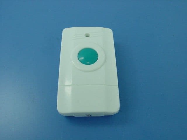
Click to zoom
Application Details
- Equipment Class
- CRR - Superregenerative Receiver
- Date of Grant
- Feb 07, 2002
- Application Purpose
- Original Equipment
- Date of Application
- Feb 07, 2002
- Equipment Note
- Wireless Door Chime
- Frequency Range
- 311.30000000 - 312.30000000
- Company
- Precise Int'l (H.K.) Ltd.
- Country
- Hong Kong
Documents & Files
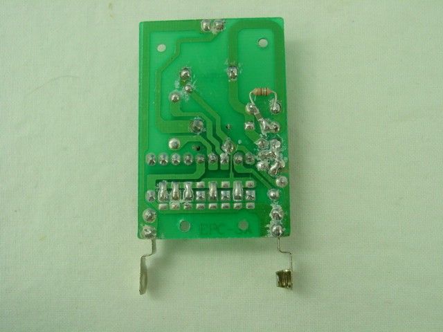
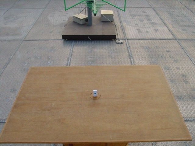
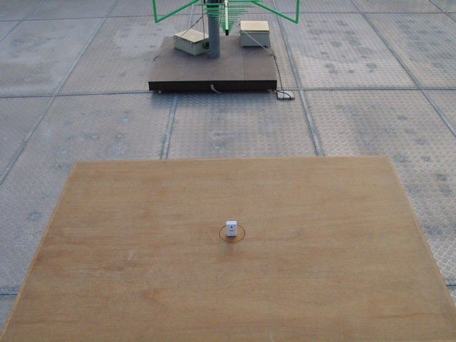
Document Text
Text extracted from the exhibit documents filed with the FCC. Open a document above to read the original.
Users Manual
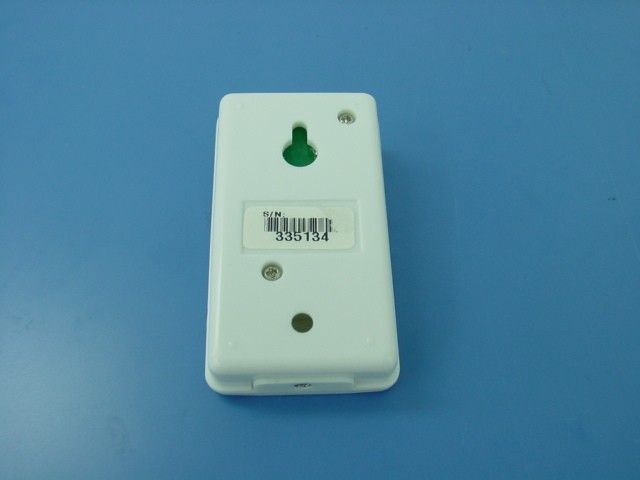
PRECAUTIONS : WARNING : Changes or modifications to this unit not expressly approved by the party responsible for compliance could void the user authority to operate the equipment. NOTE : This equipment has been tested and found to comply with the limits for a Class B digital device, pursuant to Part 15 of the FCC Rules. These limits are designed to provide reasonable protection against harmful interference in a residential installation. This equipment generates, uses and can radiate radio frequency energy and, if not installed and used in accordance with the instruction, may cause interference to radio communications. However, there is no guarantee that interference will not occur in a particular installations. If this equipment does cause harmful interference to radio or television reception, which can be determined by turning the equipment off and on, the user is encouraged to try to correct the interference by one or more of the following measures: • Reorient or relocates the receiving antenna. • Increase the separation between the equipment and receiver. • Connect the equipment into an outlet different from that to which the receiver is needed. • Consult the dealer or an experienced radio / TV technician for help. OPERATION PROCEDURE For Transmitter unit – 1) Put a 12V battery (provided) into the battery slot. 2) Use the double-sided adhesive tape to stick on the back side of the unit, then put the unit on your desired position near the door, or just use the wall-mount hole on the back side of the unit, then mount the unit on your desired position near the door. (Avoid putting the unit nears the metal object). 3) LED indicator is on when pressing the button. In case there is no LED indicator, it indicates that the battery is dry and need to replace a new battery. For Receiver unit – 1) Put 2 pcs AA size battery into the battery slot (alkaline batteries are recommended). 2) Put the unit at your desired position. 3) LED indicator is on when the transmitter button is pressed. 4) If there is no LED indicator or sound, it indicates that the battery is dry and need to replace a new battery. BATTERY PRECAUTIONS Follow these precautions when using batteries in this device: 1. Use only the size and type of batteries specified. 2. Be sure to follow the correct polarity when installing the batteries as indicated in the battery compartment. Reversed batteries may cause damage to the device. 3. Do not mix different types of batteries together (e.g. Alkaline and Carbon-zinc) or old batteries with fresh ones. 4. If the device is not to be used for a long period of time, remove the batteries to prevent damage or injury from possible battery leakage. 5. Do not try to recharge batteries not intended to be recharged; they can overheat and rupture. (Follow battery manufacturer’s directions.)
Operational Description
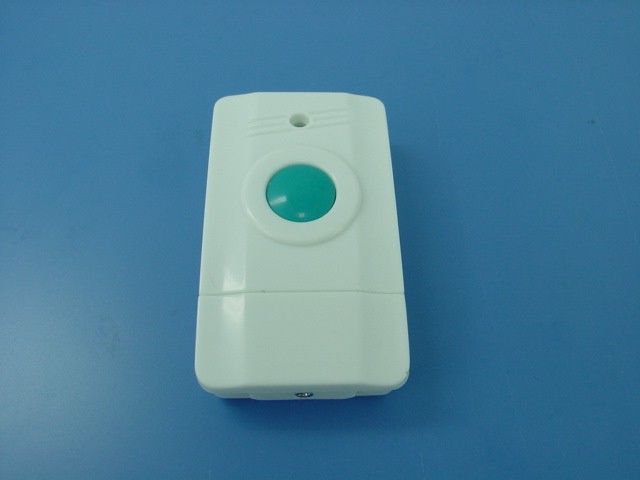
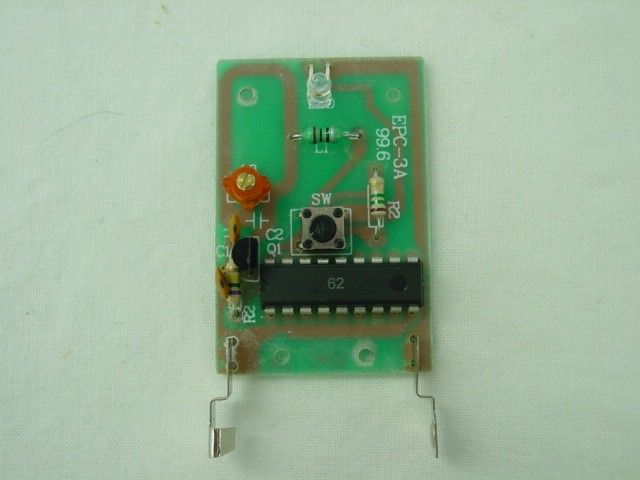
Operation Description of the Wireless Door Chime The wireless door chime transmits at 313.77 MHz which is controlled by a RC circuit. It is powered by a 12 V battery. There is only a single button in the center of the transmitter. When the button is pressed once, it transmit a radio frequency and the door bell (receiver) will be sounded. No more signal is transmitted when the button is released. Refer to the circuit design, the circuit description are as follows : IC1 and associated circuit act as encoder. Q1 and associated circuit act as oscillator and amplifier.
Test Report
TEST REPORT Room 1401-3, Yan Hing Centre, 9-13 Wong Chuk Yeung St.., Fo Tan, Shatin, Hong Kong. Tel: (852) 2698 8198 Fax: (852) 2695 4177 E-mail: [email protected] Web Site: http://www.cmatcl.com This report is restricted by the Terms and Conditions as stated on the back page of the application form or it can be provided on request. Report No. : AB018583-1 Date : 2002 January 10 Client : Precise Int’l (H.K.) Ltd. Flat E, 3/F., Block 4, Golden Dragon Ind. Center, 182-190 Tai Lin Pai Road, Kwai Chung, N. T., Hong Kong. Sample Description : Sample stated to be Wireless Door Chime (Transmitter). Model No. : MSR#7077, E-1909, E-1908, 301, 302 Rating : 1 x 12 V battery No. of sample(s) : One(1) piece *** Date Received : 2001 December 20. Test Period : 2001 December 20 – 2002 January 08. Test Requested : FCC Part 15 Certification Test Method : FCC Rules and Regulations Part 15 – May 2001 ANSI C63.4 – 1992 Test Result : See attached sheet(s) from page 2 to 10. Conclusion : The submitted sample was found to comply with requirement of FCC Part 15 Subpart C. For and on behalf of CMA Testing and Certification Laboratories Authorized Signature : Page 1 of 10 Danny Chui EMC Engineer - EL. Division FCC ID : P5P-TX-3038T This document shall not be reproduced either in full or in part except with written approval by the Authorized Representative of CMA Testing. TEST REPORT Room 1401-3, Yan Hing Centre, 9-13 Wong Chuk Yeung St.., Fo Tan, Shatin, Hong Kong. Tel: (852) 2698 8198 Fax: (852) 2695 4177 E-mail: [email protected] Web Site: http://www.cmatcl.com This report is restricted by the Terms and Conditions as stated on the back page of the application form or it can be provided on request. Report No. : AB018583-1 Date : 2002 January 10 Table of Contents 1 General Information ..................................................................................................................... 3 1.1 General Description ................................................................................................................ 3 1.2 Related Submittal Grants ........................................................................................................ 3 1.3 Location of the test site ........................................................................................................... 4 1.4 List of measuring equipment .................................................................................................. 5 2 Description of the radiated emission test ..................................................................................... 6 2.1 Test Procedure ........................................................................................................................ 6 2.2 Test Result .............................................................................................................................. 6 2.3 Radiated Emission Measurement Data ................................................................................... 7 3 Description of the Line-conducted Test .......................................................................................8 3.1 Test Procedure ........................................................................................................................ 8 3.2 Test Result .............................................................................................................................. 8 3.3 Graph and Table of Conducted Emission Measurement Data................................................ 8 4 Photograph.................................................................................................................................... 9 4.1 Photographs of the Test Setup for Radiated Emission and Conduction Emission ................. 9 4.2 Photographs of the External and Internal Configurations of the EUT.................................... 9 5 Supplementary document .............................................................................................................. 9 5.1 Bandwidth............................................................................................................................... 9 6 Appendices .................................................................................................................................. 10 Page 2 of 10 FCC ID : P5P-TX-3038T This document shall not be reproduced either in full or in part except with written approval by the Authorized Representative of CMA Testing. TEST REPORT Room 1401-3, Yan Hing Centre, 9-13 Wong Chuk Yeung St.., Fo Tan, Shatin, Hong Kong. Tel: (852) 2698 8198 Fax: (852) 2695 4177 E-mail: [email protected] Web Site: http://www.cmatcl.com This report is restricted by the Terms and Conditions as stated on the back page of the application form or it can be provided on request. Report No. : AB018583-1 Date : 2002 January 10 1 General Information 1.1 General Description The equipment under test (EUT) is a transmitter for a wireless door chime operating at 313.7747 MHz which is controlled by a RC circuit. The EUT is powered by a 12 V battery. There is only a single button in the center of the EUT. When the button is pressed once, it transmit a radio frequency and the door bell (receiver) will be sounded. No more signal is transmitted when the button is released. The brief circuit description is listed as follows : - IC1 and associated circuit act as encoder - Q1 and associated circuit act as oscillator and amplifier The models EL-1909, EL-1908, 301 and 302 are the same as model MSR#7077 in hardware aspect. The difference in model numbers serves as marketing strategy. 1.2 Related Submittal Grants This is a single application for certification of a transmitter. The receiver of this transmitter is authorized by Certification procedure. Page 3 of 10 FCC ID : P5P-TX-3038T This document shall not be reproduced either in full or in part except with written approval by the Authorized Representative of CMA Testing. TEST REPORT Room 1401-3, Yan Hing …
Text truncated - open the document above for the full version.
Contact Information
Applicant
Eva Wong(Marketing Manager)
Test Firm
CMA Industrial Development Foundations LimitedStephen Lam
Technical Specifications
| # | Rule Parts | Frequency Range | Power Output |
|---|---|---|---|
| 1 | 15B | 311.3 MHz - 312.3 MHz | - |
Other Applications from Precise Int'l (H.K.) Ltd.
P5P-TX-3038T
Jan 21, 2002Wireless Door Chime
Equipment Class
DSC - Part 15 Security/Remote Control Transmitter