P63SALO010Key Fob Transmitter
IDAFAB Engineering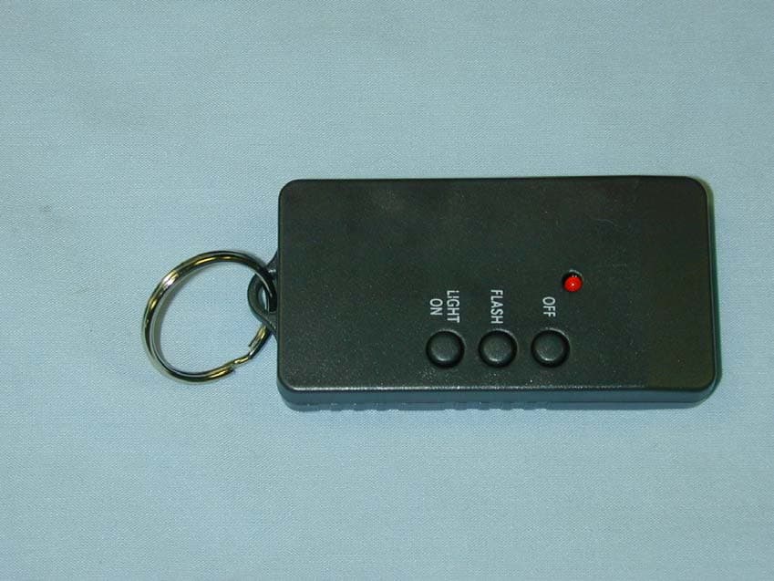
Click to zoom
Application Details
- Equipment Class
- DSC - Part 15 Security/Remote Control Transmitter
- Date of Grant
- Jul 14, 2002
- Application Purpose
- Original Equipment
- Date of Application
- Jul 14, 2002
- Equipment Note
- Key Fob Transmitter
- Frequency Range
- 315.00000000 - 315.00000000
- Company
- IDAFAB Engineering
- Country
- United States
Documents & Files
Document Text
Text extracted from the exhibit documents filed with the FCC. Open a document above to read the original.
Users Manual
Auto-Eye Personal Anti-Crime Light $59.95 suggested mfg. price Provides 25-60 feet of safe, well-lit space all around your automobile! Activates by remote control from over 300 feet away! Finds your car instantly without unlocking doors! Finds someone hiding in or around your car! Auto-Eye flashes in panic alarm mode! Great for blackouts or dark garages and streets! Plugs into lighter socket and suspends from rear-view mirror! Stores easily after use in beverage container! Replaces flares, flashlights and spotlights! Portable (with battery pack) and water-resistant! Great for home, boat, or campsite! Scientifically designed and measured on photospectrometer! Auto-Eye is visible for about 1/2 mile! Super-bright Halogen lamp delivers illumination 360 degrees! NEVER PARK IN THE DARK! Model #911 U.S Patent No. No. 5,988,838 , T.M., Lightsafer, Inc . Important! Read Before Use. Congratulations on purchasing Auto-Eye Personal Anti-Crime Light! Auto-Eye Personal Anti-Crime Light is an innovative hi-power illumination system carefully designed to increase comfort, convenience and safety for the user. Auto-Eye Personal Anti-Crime Light was invented so that you NEVER PARK IN THE DARK! @TM Auto-Eye Personal Anti-Crime Light is very bright and must be powered by the automobile battery. IT IS IMPORTANT TO TEST THIS PRODUCT TO DETERMINE WHETHER THE LIGHTER PLUG IS “LIVE.” Testing the product: Plug Auto-Eye Personal Anti-Crime Light into the lighter plug WITHOUT THE KEY IN THE IGNITION. Activate the remote unit and notice whether the LED light on the hand-held transmitter turns on. If the product does not illuminate, carefully turn the key to activate the auto battery WITHOUT STARTING THE ENGINE. If Auto-Eye Personal Anti-Crime Light only works when the key is in the ignition, the lighter plug must be modified so that is “live.” Converting your lighter plug so that it works without the key in the ignition requires running a “hot” lead wire to the lighter plug assembly. Your auto dealer or mechanic can convert your lighter plug to allow Auto-Eye Personal Anti-Crime Light to run off of your automobile battery. Or, purchase an optional lighter plug for your car (available at auto parts, electrical supply or hobby stores) in order to install your Auto-Eye Personal Anti-Crime Light quickly and inexpensively. If you do not wish to use the lighter plug to activate Auto-Eye Personal Anti-Crime Light, you must purchase the rechargeable battery pack for convenient, completely portable use. Replacing the bulb: Auto-Eye Personal Anti-Crime Light uses a 35-watt Halogen lamp and scientifically designed lens to intensify the beam at the desired level. Halogen lamps become VERY HOT after use. You must never handle the lamp directly. To change bulb, carefully turn the top of the lantern counterclockwise. Let the unit cool for an additional 15 minutes before changing the lamp. Use a soft cloth to remove the bulb from the socket assembly by pulling bulb gently, directly upward. Replace with a similar bulb. Do not exceed 35 watts! When replacing the dome top, line up the bulb with the metal guide, keeping the top of the bulb within the opening of the metal guide. Line up screw heads with the metal clips attached to the lens section. Gently turn the dome top clockwise until the unit is secure. Test to make certain the top is attached securely. Installing the Product: When leaving vehicle, suspend Auto-Eye Personal Anti-Crime Light from the rear-view mirror by placing hook over rear-view mirror post. Or, place unit on level dashboard. Plug unit into automobile lighter socket. When returning to vehicle, TURN LIGHT OFF BEFORE ENTERING AUTOMOBILE! Auto-Eye Personal Anti-Crime Light is very bright, and it is recommended you do not directly look at the product unless far away. UNPLUG Auto-Eye Personal Anti-Crime Light FROM LIGHTER PLUG. HOLD PRODUCT FROM HOOK, STRAP, OR BOTTOM. PRODUCT BECOMES WARM AFTER EXTENDED USE (OVER 10 MINUTES). DO NOT GRAB PRODUCT FROM CLEAR LENS OR UPPER DOME. WARNING: When not in use, store in beverage container. NEVER DRIVE WITH Auto-Eye Personal Anti-Crime Light SUSPENDED FROM REAR-VIEW MIRROR!! It is unsafe and illegal to operate a motor vehicle with anything suspended from rear-view mirror or on dashboard. Manufacturer or distributor assumes no responsibility for inappropriate use of product. Conditions Affecting Use: Auto-Eye Personal Anti-Crime Light is activated by radio-frequency remote control. Reception will vary depending upon electrical interference in the environment. Auto-Eye Personal Anti-Crime Light works best in an open area with a minimum of interference, or “noise.” Under optimal circumstances, Auto-Eye Personal Anti-Crime Light may activate from up to an astounding 900 feet OR MORE. The optimal environment is an open field away from electrical generators. The ideal environment is at night and away from lighting structures, radio towers, antennas, or other electrical generators. To maximize range, hold transmitter with keys in the palm of your hand. Do not grasp the transmitter on the opposite end of the key chain. Point transmitter in the general direction of your Auto-Eye Personal Anti-Crime Light. The bottom button is “ON,” the middle button is the “FLASH mode,” and the top button is “OFF.” Push the desired button in the general direction of the vehicle. Auto-Eye Personal Anti-Crime Light is most useful in the absence of available security lighting. In dimly-lit parking lots, Auto-Eye may not seem as bright as when used in a darker environment. Auto-Eye is rated to deliver security levels of illumination at a distance of up to 25 feet from the automobile in a completely dark environment. If product activation is consistently less than 100 feet, replace battery in hand-held transmitter. Open battery door and carefully replace old battery with new battery. If after replacing battery, product performance does not improve, contact manufacturer for replacement of product. Accessories: …
Text truncated - open the document above for the full version.
Cover Letter(s)
Murray Rudenberg,Ph.D. President, Lightsafer, Inc. 2423 Camino Del Rio So. Ste. 106 San Diego, CA 92108 (858) 509-7575 Fax (619) 497-1993 Hm. (858) 794-0370 e-mail: [email protected] September 23, 2001 Federal Communications Commission 7435 Oakland Mills Road Columbia MD 21046 Dear Sirs: This is to request that all schematics associated with the Product, currently called KnightEye, remain confidential. These products are pioneering a new application in the market place, and as we near product release, we feel that confidentiality is required in order to protect our market position at this sensitive time. Thank you very much. Sincerely, Murray Rudenberg, Ph.D.
Cover Letter(s)
Hi Tim Pleases see responses to your queries below : 1) I will upload the new confidentiality agreement 2) The test report has been amended to reflect this 3) I will upload the block diagram 4) Yes. There is a statement on page 13 of the test report to reflect this was done. 5) There is a plot of the duty cycle on page 9 of the test report that shows the pulse train repeats at approximately 62ms after the beginning of the first pulse train. (10ms/div times 6.2 divisions) 6)The data was taken using a peak detector. The test report has been changed to reflect this. (100kHz RBW/100kHz VBW) 7) The 315MHZ data on page 15 is bogus. Data on this page was taken in an anechoic chamber and was recorded for reference only to reflect that the device was transmitting. Reference to 315MHz has been removed from test report. No emissions were detected above 1GHz and the spectrum was searched to the 10th harmonic of the carrier. 8) This measurement was taken using a PEAK detector. The report has been changed to reflect this. 9) Yes this application is only for the transmitter. Client will use DOC for receiver. Tim, I have been trying to upload documentd to your site both for this application and also for Ryko. I am having many problems with it. I will go ahead and try again but if all else fails I will have to email them to you. For this application (IDAFAB) I am going to upload the revised test report, block diagram and also the confidentiality request. If you have any more questions please let me know. Thank you for your help and patience Best Regards Denise To: [email protected] Subject: RE: Review of IDAFAB Engineering Application, FCC ID: P63SALO010 Page 1 of 2In 7/15/2002Printed for "Timothy R. Johnson" <[email protected]> -----Original Message----- From: Timothy R. Johnson [mailto:[email protected] ] Sent: Friday, May 24, 2002 10:41 AM To: David Light; Denise Godfrey Subject: Review of IDAFAB Engineering Application, FCC ID: P63SALO010 David/Denise, We haven't heard from you in awhile. We were wondering when we might expect a response to our questions? Please let us know. Thank You, Tim ---------------------------------Original email (5/10/02) --------------------------------- David/Denise, Attached are comments regarding review of this application. Thank You, Timothy R. Johnson, NARTE Certified EMC Engineer (No. EMC-002205-NE) Examining Engineer American TCB, Inc. 6731 Whittier Ave. McLean, VA 22101 email: [email protected] alternate email: [email protected] mobile number: 404-414-8071 corporate phone: 703-847-4700 corporate fax: 703-847-6888 Page 2 of 2In 7/15/2002Printed for "Timothy R. Johnson" <[email protected]>
Cover Letter(s)
American Telecommunications Certification Body Inc. 6731 Whittier Ave, McLean, VA 22101 May 10, 2002 RE: IDAFAB Engineering FCC ID: P63SALO010 After a review of the submitted information, I have a few comments on the above referenced Application. 1) It does not appear that confidentiality was requested on any exhibits. Please confirm that this is NOT requested for any exhibits. 2) The test report states the frequency range is 260-470 (page 5 of 27). The frequency range listed here and on the 731 should be the actual tuning or transmission range of the TX. If 315 MHz is the only operational frequency, please adjust both the 731 and test report from "260-470" to "315" MHz. 3) Please provide a block diagram of the TX that includes the frequencies as specified in CFR 2.1033(a)(5). 4) Please confirm that this device was positioned in 3 orthogonal planes to obtain worse case results. 5) Please provide plots showing that the duty cycle is repeats approximately every 60 msec as stated by the operational description. 6) For the table on page 14 of 27, please explain which type of detector was used to obtain the original meter reading (Peak, QP, Average) and the associated bandwidth settings used. 7) Please explain the difference between the 315 MHz data listed on page 14 and 15. 8) The 5 th harmonic on page 15 of 27 appears to be taken with an average detector according to the table. The RBW and VBW settings state they are 1 MHz, while page 13 of 27 states that RBW = 1 MHz and the VBW = 3MHz. Please clarify the actual settings used. Please note that for OOK type devices measurements should be made with a peak detector (for > 1 GHz, this is defined as RBW=VBW=1MHz) and corrected by the duty cycle for comparison to the average limits. There is not actually an average measurement. 9) FYI, This application only covers the transmitter. The receiver portion of this system must be approved using a DoC or a separate application for certification. 10) FYI, For future applications, please include an separate exhibit that only shows the test photographs. Timothy R. Johnson Examining Engineer mailto: [email protected] The items indicated above must be submitted before processing can continue on the above referenced application. Failure to provide the requested information may result in application termination. Correspondence should be considered part of the permanent submission and may be viewed from the Internet after a Grant of Equipment Authorization is issued. Please do not respond to this correspondence using the email reply button. In order for your response to be processed expeditiously, you must submit your documents through the AmericanTCB.com website. Also, please note that partial responses increase processing time and should not be submitted. Any questions about the content of this correspondence should be directed to the sender.
Operational Description
01/31/2002 Page 1 of 4 To; Nemko Dallas, Inc. 802 North Kealy Ph 972-436-9600 Lewisville, Texas 75089 Fax 972-436-2667 C /o Susan Griffith [email protected] from; IDAFAB Engineering C /o Glenn Borland 2459 Fawn Creek Lane Ph 760-743-7726 Escondido, CA 92026 Fax 760-745-0014 Brief operational description of the SALIO wireless switched light. The SALIO wireless light system consists of a handheld wireless transmitter and a low cost receiver located in the base of a portable light. Desired operational range was to be greater than 450 feet line of sight. Antennas are to be self contained in both the receiver and transmitter. Operation was to be under Article 47, part 15.XXX Transmitter; The RF portion of the transmitter consists of a SAW (F1) stabilized Pierce oscillator (Q1) directly coupled to a tuned antenna etched on the transmitter PC board. The frequency of operation is 315 MHz. The oscillator is on/off keyed via the base of the oscillator transistor. The on/off keying signal is derived from a PTC remote control encoder (U1). The "data" rate is approx. 500 symbols(bits)/sec. The bit period is approx. 2 mSec and data is encoded as 0.5 mSec hi (xmitter on) or 1.5 mSec hi (xmitter on) the balance of the bit period low (xmitter off). The length of a data packet (all information needed for address codes and data to be sent [i.e.. light on/off or blinking]) is approx. 45 mSec and repeats (as long as the transmitter button is held down) approx. every 60 mSec. Release of the button stops the transmission. Power for the whole transmitter section runs off a raw +12 volt battery (BATT1). Address selection is accomplished via jumpers (J1 through J8) Receiver; The receiver is a single conversion super heterodyne with a first IF of 1.8 MHz. The LO for the receiver is (as in the transmitter) a SAW (F1) stabilized Pierce oscillator (Q1) operating at a frequency of 316.8 MHz. The antenna for the receiver is a tuned design utilizing the top and bottom reflectors of the light. The bottom reflector is ground ant the top is tuned with a series L and connected to the receiver input matching stage (C11, L1, C12, & C10). The detector responds to On/Off keying and the data is derived from the detector stage of the receiver. A single pole of post detection filtering is used (C8). IDAFAB Engineering 01/31/2002 Page 2 of 4 The majority of the RF portion of the receiver is built around an economical HiMark UHF receiver "chip" (U1). This unit contains RF amplifier, First (and only) mixer, IF filter (such as it is), successive detection "limiter", and a comparator. Data from the receiver is then sent to a PTC decoder chip which matches up the address and, if the addresses match, sends out the appropriate commands to the light. The command breakdown is as follows; 1) Light on 2) Light on (blinking) 3) Light off The light is switched on and off by way of a N channel enhancement mode IGFET (U5). The IGFET is driven with two bipolar transistors (Q3 & Q5). The input to the bipolar transistors is a two input diode OR gate. The light on/off input comes from the decoder chip (U3). The flashing light input comes from a simple 555 timer (U2). The power to the 555 is switched with the other output from the decoder chip via Q2 & Q4. The receiver, LO, and decoder runs off a +5 volt regulator (U4). The 555 timer, FET driver, and the light itself (LAMP1) runs off the raw +12 volts. Address selection is accomplished via jumpers (J1 through J8). IDAFAB Engineering
Test Report
NEMKO Test Report: 1L0698RUS1 Applicant: IDAFAB Engineering 2459 Fawn Creek Lane Escondido, CA 92026 Equipment Under Test: Auto-Eye Personal Anti-Crime Light Remote Control (E.U.T.) In Accordance With: FCC Part 15, Subpart C For Low Power Transmitters Operating Periodically In The Band 40.66 - 40.77 MHz And Above 70 MHz Tested By: NEMKO Dallas, Inc. 802 N. Kealy Lewisville, TX 75057-3136 Authorized By: David Light, Wireless Lab Supervisor Date: 5 March 2002 Total Number of Pages: 27 Nemko Dallas, Inc. FCC PART 15, SUBPART C POWER TRANSMITTERS EQUIPMENT: Auto-Eye Personal Anti-Crime Light Remote Control PROJECT NO.: 1L0698RUS1 TABLE OF CONTENTS Section 1. Summary of Test Results..........................................................................................3 Section 2. Equipment Under Test (E.U.T.)................................................................................5 Section 3. Transmission Requirements......................................................................................7 Section 4. Radiated Emissions.................................................................................................13 Section 5. Occupied Bandwidth...............................................................................................17 Section 6. Frequency Tolerance...............................................................................................19 Section 7. Periodic Alternate Field Strength Requirements....................................................20 Section 8. Powerline Conducted Emissions............................................................................21 Section 9. Block Diagrams .......................................................................................................22 Section 10. Test Equipment List................................................................................................25 ANNEX A - RESTRICTED BANDS..........................................................................................26 Page 2 of 27 Nemko Dallas, Inc. FCC PART 15, SUBPART C POWER TRANSMITTERS EQUIPMENT: Auto-Eye Personal Anti-Crime Light Remote Control PROJECT NO.: 1L0698RUS1 Section 1. Summary of Test Results Manufacturer: IDAFAB Engineering Model No.: Auto-Eye Personal Anti-Crime Light Remote Control General: All measurements are traceable to national standards. These tests were conducted on a sample of the equipment for the purpose of demonstrating compliance with Part 15, Subpart C, Paragraph 15.231. All tests were conducted using measurement procedure ANSI C63.4-1992. Radiated emissions are made on an open area test site. A description of the test facility is on file with the FCC. New Submission Production Unit Class II Permissive Change Pre-Production Unit THIS TEST REPORT RELATES ONLY TO THE ITEM(S) TESTED. THE FOLLOWING DEVIATIONS FROM, ADDITIONS TO, OR EXCLUSIONS FROM THE TEST SPECIFICATIONS HAVE BEEN MADE. See “ Summary of Test Data”. NVLAP LAB CODE: 100426-0 NEMKO Dallas Inc. authorizes the above named company to reproduce this report provided it is reproduced in its entirety and for use by the company’s employees only. Any use which a third party makes of this report, or any reliance on or decisions to be made based on it, are the responsibility of such third parties. NEMKO Dallas Inc. accepts no responsibility for damages, if any, suffered by any third party as a result of decisions made or actions based on this report. This report applies only to the items tested. Page 3 of 27 Nemko Dallas, Inc. FCC PART 15, SUBPART C POWER TRANSMITTERS EQUIPMENT: Auto-Eye Personal Anti-Crime Light Remote Control PROJECT NO.: 1L0698RUS1 Summary Of Test Data Name of Test Paragraph No. Results Transmission Requirements 15.231(a) Complies Radiated Emissions 15.231(b) Complies Occupied Bandwidth 15.231(c) Complies Frequency Tolerance 15.231(d) Not Applicable Alternate Field Strength Requirements 15.231(e) Not Applicable Powerline Conducted Emissions 15.207 Not Applicable Footnotes: 1. Frequency Tolerance is not required due to the fact that the device does not operate in the band of 40.66-40.70 MHz 2. Alternate Field Strength Requirements were not needed due to the device’s compliance with BW measurements. 3. Powerline Conducted Emissions is not required as this is a battery-operated device. Page 4 of 27 Nemko Dallas, Inc. FCC PART 15, SUBPART C POWER TRANSMITTERS EQUIPMENT: Auto-Eye Personal Anti-Crime Light Remote Control PROJECT NO.: 1L0698RUS1 Section 2. Equipment Under Test (E.U.T.) General Equipment Information Frequency Range: 315 MHz Operating Frequency(ies) of Sample: 315 MHz Supply Power Requirement: 12V battery Duty Cycle Correction Factor: -6.4 dB Page 5 of 27 Nemko Dallas, Inc. FCC PART 15, SUBPART C POWER TRANSMITTERS EQUIPMENT: Auto-Eye Personal Anti-Crime Light Remote Control PROJECT NO.: 1L0698RUS1 Description of E.U.T. A small key fob transmitter that has three buttons all of which transmit at the same frequency in this case 315 MHz. It can be set up to turn on lights, turn off lights, and to lock/unlock doors. The transmission is pulse based giving it a minor duty cycle adjustment for most measurements in this procedure. Modifications Incorporated in E.U.T. Page 6 of 27 Nemko Dallas, Inc. FCC PART 15, SUBPART C POWER TRANSMITTERS EQUIPMENT: Auto-Eye Personal Anti-Crime Light Remote Control PROJECT NO.: 1L0698RUS1 Section 3. Transmission Requirements NAME OF TEST: Transmission Requirements PARA. NO.: 15.231(a) TESTED BY: Lance Walker DATE: 01/02/2002 Minimum Standard: 15.231(a) Continuous transmissions such as voice, video or data transmissions are not permitted. 15.231(a)(1) A manually operated transmitter shall employ a switch that will automatically deactivate the transmitter within not more than 5 seconds after being released. 15.231(a)(2) A transmitter activated automatically shall cease transmission within 5 seconds of activation. 15.231(a)(3) Periodic transmissions at regular pre- determined intervals are…
Text truncated - open the document above for the full version.
Test Setup Photos
Nemko Dallas, Inc. FCC PART 15, SUBPART C POWER TRANSMITTERS EQUIPMENT: Auto-Eye Personal Anti-Crime Light Remote Control PROJECT NO.: 1L0698RUS1 Radiated Photographs (Worst Case Configuration) FRONT VIEW REAR VIEW Page 16 of 27
Contact Information
Applicant
Glenn Borland(Owner)
[email protected](760) 743-7726
Technical Contact
Nemko Dallas, Inc.David Light
[email protected]972-436-9600
802 N Kealy Rd. · Lewisville, Texas · United States
Non-Technical Contact
Nemko Dallas, Inc.Denise Godfrey
[email protected]972-436-9600
Test Firm
Nemko Dallas, Inc.Michael Cantwell
Technical Specifications
| # | Rule Parts | Frequency Range | Power Output |
|---|---|---|---|
| 1 | 15.231 | 315 MHz - 315 MHz | - |