P6YAD688BBase Unit
Aura Communications Incorporated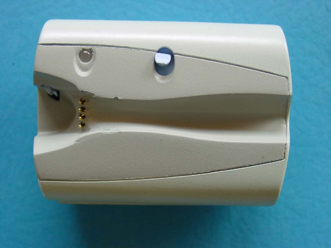
Click to zoom
Application Details
- Equipment Class
- DXT - Part 15 Low Power Transceiver, Rx Verified
- Date of Grant
- Jul 21, 2003
- Application Purpose
- Original Equipment
- Date of Application
- Jul 21, 2003
- Equipment Note
- Base Unit
- Frequency Range
- 13.56000000 - 13.96000000
- Country
- United States
Documents & Files
Document Text
Text extracted from the exhibit documents filed with the FCC. Open a document above to read the original.
Users Manual
Wireless Headset System Wireless Headset Model: AD688H Base unit Model: AD688B User’s Guide Package Contents Retainer hook Headset release LED Docking Connector Base Unit Headset Unit Volume Button Flash Button Noise Canceling Microphone Speaker Get Ready • Insert AA battery into Base. • Dock headset onto base to charge. Get Set • Allow 4 hours for full charge. • Insert coiled cord into base and cell phone headset jacks. Go • Use your phone and Docker headset just like a wired headset. When not in use • Dock the headset to the base. • The base will automatically keep the headset fully charged. Battery Care • Insert AA Battery - Battery button end (+) at the flat spring - Green Light Indicates normal operation - Red light indicates AA battery is low. Replace the battery at your earliest convenience. - Remove spent batteries from the housing to avoid damage from leakage. • Docking charges the headset - Solid light for 5 to 30 seconds while the base checks the headset battery level. - Light blinks once every 3 seconds during charge. - Light turns off when the headset is fully charged. Connecting to your phone • A short coiled cord is provided • Insert one end into the Docker headset jack • Insert the other end into the cell phone. • The light will blink once per second when the headset is removed from the base. To suspend headset operation • Dock the headset to the base • Hold the Flash button until the LED blinks rapidly (about 5 times per second) • Release Flash button • Headset will turn on for use when removed from the dock. Trouble Indicator • An amber flashing light on the base indicates trouble. Dock the headset and wait for a blinking green light Customize your headset for your convenience. • Adjust Headset volume with the volume button. Tone Meaning 1 Beep Volume was changed 2 High Beeps Maximum Volume 2 Low Beeps Minimum Volume • The headset will retain the volume setting for the next time you use the phone, but it can be readjusted any time. Change the ear you use • Grasp the hook at the base near the headset post. • Gently but firmly pull the ear-hook off of the post. • Turn the ear hook over. • Push the ear hook back over the post Flash Button Use • Your Docker headset will send flash signals to your phone when the Flash button is pushed. • Your phone will determine what the Flash button will initiate. (Refer to your phone’s user Manual.) • Many phones with voice recognition will be enabled for voice reception by a flash Tones Provide Status Information Tone Meaning 2 quick beeps per second for 8 seconds Base and headset are out of range 3 quick beeps every 45 seconds Low headset battery 6 quick beeps Headset is shutting down due to a critically low battery Specifications Audio Jack 2.5mm, 3 pin Adapters Included Yes Typical Use 3 months Based on an average of 500 minutes use per month Range 1.5 Meters Base Battery AA Alkaline Headset Battery 40mAH NiMH chargeable, non-replaceable Headset Weight 18 grams Base Weight 50 grams with AA Headset Dimensions L105 X W21mm Base Dimensions L64 X W46 X H21mm Earhook Replaceable Extra provided End call (flash) ready Yes End call tone Yes Headset volume control Yes Battery low warning Yes - Tones / LED Out of range warning Yes - Tones Charge indicator Yes - LED Belt attachment Yes FCC Compliance By manufacturer Transmission type Magnetic Induction Troubleshooting Problem Solution No Light No sound 1. Check AA battery orientation 2. Replace AA Battery, Charge Headset Red light Replace AA battery at your earliest convenience Flashing Orange Light Dock the headset and wait up to 30 seconds for normal flashing green light Phone does not respond to the headset Coiled cord is not properly connected to the phone People say my voice is too faint (or too loud) Adjust the microphone volume 1. Undock the headset 2. Place a phone call to someone who will help you set a comfortable level 3. Hold the volume button down until the light is continuously lit 4. Release the volume button 5. Light will blink 1, 2, 3, times (low medium or high) to indicate the current microphone setting. 6. Press and release the volume button once for each level change to cycle through the settings. 7. Confirm the best setting with the call recipient. 8. Wait 15 seconds without pressing any buttons for the units to return to normal operation. Safety and Additional Information • Avoid extreme temperatures, moisture and dust • Clean only with a soft, dry cloth • Do not attempt to open the units. There ar e no user serviceable parts inside. Doing so will void the warranty • Keep the headset docked to the base when not in Use • Replace the AA Base battery when the light turns red. • Do not bend the housing or microphone boom. • Check laws and regulations for the use of mobile phones and hands free equipment in your area • Always give full attention to driving and pull off the road and park before making or answering a call if driving conditions so require. • Your Docker headset operates at 13.56 MHz at power levels typically less than 1/10,000,000 that of your cell phone. • Do not use your Docker headset near medical equipment without requesting permission. • If your are using any personal medical devices e.g. a pace maker or hearing aid, please refer to the appropriate docum entation or the medical equipment manufacturer. • Turn off all electronic devices in any area with a potentially explosive or flammable atmosphere • Follow directions to suspend operation when instructed by aircraft personnel to turn off all electronic devices. • Recharge your headset only at temper atures between 0 and 65 C or battery damage may occur. Warranty Aura Communications warrants that Pr oducts delivered hereunder, under normal use, shall be free of defects in materials and workmanship and comply with the Aura’s Product Specification for a peri od of three (3) months from the date of purchase. If, during this warranty period, any Product is defective, the buyer shall return the unit with dated proof…
Text truncated - open the document above for the full version.
External Photos
Base Unit Model AD688B-X Photos Photo 2. Base unit: Top view
External Photos
Base Unit Model AD688B-X Photos Photo 3. Base unit: Bottom view
ID Label/Location Info
Aura Communications Inc. Base unit Model : AD688B-X FCC ID Label Notes: 1. Material: UL approved 2mil matte metallic mylar with adhesive backing. 1 mil clear mylar overlaminate. 2. All text is black 3. Font #8, Ariel Narrow Orig . 06.26.02 A.Viner Checked Rev. Scale 5 : 1 Sheet 1 of 1 DRG No. A Aura Communications Inc. Base Mod: AD688B-X FCC ID: P6YAD688B 10 mm 30 mm
ID Label/Location Info
Aura Communications Inc. Base unit Model : AD688B-X FCC ID Label location Orig . 06.20.03 A.Viner Checked Rev. Scale 2 : 1 Sheet 1 of 1 DRG No. A Location of the FCC ID Label in the Battery Compartment of the Base enclosure 45 mm FCC ID Label Location Door of the battery compartment (open) Battery Compartment (door open) 10 mm 1 0 m m 40 mm 60 mm
Internal Photos
Base Unit Model AD688B-X Photos Photo 6. Base unit: Printed circuit board: antennas side
Internal Photos
Base Unit Model AD688B-X Photos Photo 5. Base unit: Printed circuit board: LibertyLink chip side
Test Report
Intertek Testing Services, NA, Inc.70 Codman Hill Road Boxborough MA 01719 Aura Communications, Inc., Model No. AD688B-XDate of Test: July 1-2, 2003 FCC ID: P6YAD688B Report # 30448702FCC Part 15.209 Table of Contents 1.0Summary of Tests..................................................................................................................................................3 2.0General Description..............................................................................................................................................4 2.1Product Description................................................................................................................................4 2.2Related Submittal(s) Grants....................................................................................................................5 2.3Test Facility..............................................................................................................................................5 2.4Test Equipment and Support Equipment.............................................................................................5 3.0RF Power Output....................................................................................................................................................7 3.1Test Procedure.........................................................................................................................................7 3.2Test Results..............................................................................................................................................7 4.0Emission Bandwidth and Restricted Band Emissions.....................................................................................8 4.1Test Procedure.........................................................................................................................................8 4.2Test Results..............................................................................................................................................8 5.0 Field Strength of Spurious Radiation...................................................................................................................9 5.1Test Procedure.........................................................................................................................................9 5.2Test Results..............................................................................................................................................9 Intertek Testing Services, NA, Inc.70 Codman Hill Road Boxborough MA 01719 Aura Communications, Inc., Model No. AD688B-XDate of Test: July 1-2, 2003 FCC ID: P6YAD688B Report # 30448704FCC Part 15.209 2.0General Description 2.1Product Description The EUT is a transceiver operating at 13.56 and 13.96 MHz. It is intended to provide hands-free functionality for cell phone users. To achieve this, a Base Unit is connected to a cell phone headset output via a cable. When a call is initiated, the audio signal is carried by the cable from the phone to the Base Unit. The base unit then transmits the signal to the Wireless Headset Unit, mounted on the user’s ear, where it is converted back to audio. Both the Wireless Headset Unit and the Base Unit are transceivers. This report represents testing of the Base Unit. A production version of the EUT arrived on July 1, 2003, in Good condition. The EUT was assigned serial number 0001. Note that the EUT is battery powered and therefore line-conducted emissions testing was not required. The EUT has been tested at the request of Company:Aura Communications, Inc. 187 Ballardvale Street Wilmington, MA, 01887 Name of contact:Aron Viner Telephone:(978) 527-4130 Fax:(978) 988-3977 During testing, the EUT was activated from a fresh battery and was transmitting continuously. The EUT was manipulated in 3 orthogonal axes to determine a worst case orientation, and was rotated through 360 degrees to maximize emissions. Intertek Testing Services, NA, Inc.70 Codman Hill Road Boxborough MA 01719 Aura Communications, Inc., Model No. AD688B-XDate of Test: July 1-2, 2003 FCC ID: P6YAD688B Report # 30448705FCC Part 15.209 2.2Related Submittal(s) Grants An application for the Wireless Headset Unit was filed at the same time as this application, under the FCC ID: P6YAD688H. 2.3Test Facility Site 2C (Middle Site) is a 3m and 10m sheltered EMI measurement range located in a light commercial environment in Boxborough, Massachusetts. It meets the technical requirements of ANSI C63.4-1992 and CISPR 22:1993/EN 55022:1994 for radiated and conducted emission measurements. The shelter structure is entirely fiberglass and plastic, with outside dimensions of 33 ft x 57 ft. The structure resembles a quonset hut with a center ceiling height of 16.5 ft. The testing floor is covered by a galvanized sheet metal groundplane that is earth-grounded via copper rods around the perimeter of the site. The joints between individual metal sheets are bridged with a 2 inch wide metal strips to provide low RF impedance contact throughout. The sheets of metal are screwed in place with stainless steel, round-head screws every three inches. Site illumination and HVAC are provided from beneath the ground reference plane through flush entry ports, the port covers are electically bonded to the ground plane. A flush metal turntable with 12 ft. diameter and 5000 lb. load capacity is provided for floor-standing equipment. A wooden table 80 cm high is used for table-top equipment. The turntable is electrically connected to the ground plane with three copper straps. The straps are connected to the turntable at the center of it with ground braid. It is copper strap is directly connected to the groundplane at the edges of the turntable. The turntable is located on the south end of the structure and the antennas are mounted 3 and 10 meters away to the north. The antenna mast is a non-conductive with remote control o…
Text truncated - open the document above for the full version.
Test Report
Engineering Notes, February 2002, Rev. 1.0 Page 1 of 11 Engineering Notes Company Name:Aura Communications Model:AD688H-X and AD688B-X Project #:3044870 Notes:7/1/03 NNA Client arrived with EUT, eventually found enough test equipment to start output power measurements, measured both channel output powers @ 6m distance, EUT meets the requirements. Noticed odd peak structure with max peak offset from the fundamental by ~100-150 kHz. Fundamental was verified as actual peak emission when transmitting appropriate audio data stream through the unmodified unit; data for output power taken on the continuously transmitting version agrees with the level of the unmodified unit and therefore will be used.
Test Setup Photos
RF Output Power RF Output Power Spurious Emissions
Contact Information
Applicant
Aron I Viner(Principal Compliance Engineer)
Technical Contact
Aura Communications Inc.Aron Viner
[email protected]978 527 4130
187 Ballardvale Street · Wilmington, Massachusetts · United States
Non-Technical Contact
Aura Communications Inc.Aron Viner
[email protected]978 527 4130
Test Firm
Intertek Testing Services NA Inc.Roland Gubisch
Technical Specifications
| # | Rule Parts | Frequency Range | Power Output |
|---|---|---|---|
| 1 | 15C | 13.56 MHz - 13.96 MHz | - |
Other Applications from Aura Communications Incorporated
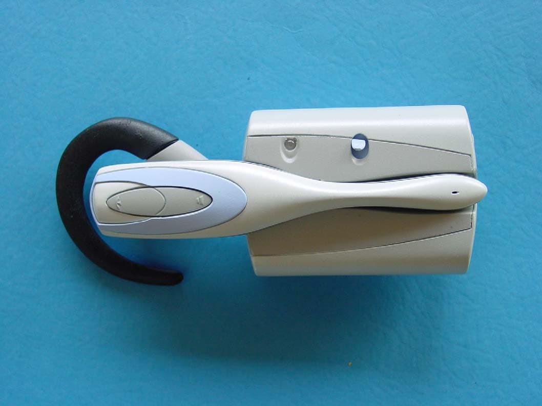
P6YAD688H
Jul 21, 2003Wireless Headset Unit
Equipment Class
DXT - Part 15 Low Power Transceiver, Rx Verified