P72WIAR3Repeater for wireless sensors
General Sensors, Incorporated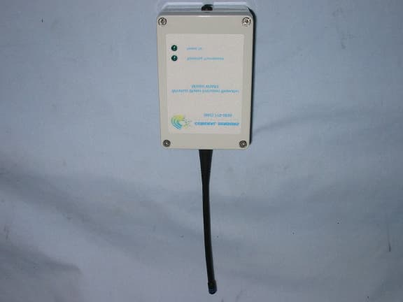
Click to zoom
Application Details
- Equipment Class
- DSC - Part 15 Security/Remote Control Transmitter
- Date of Grant
- Jul 02, 2002
- Application Purpose
- Original Equipment
- Date of Application
- Jul 02, 2002
- Equipment Note
- Repeater for wireless sensors
- Frequency Range
- 418.00000000 - 418.00000000
- Country
- United States
Documents & Files
Document Text
Text extracted from the exhibit documents filed with the FCC. Open a document above to read the original.
Users Manual
1 INSTRUCTION MANUAL Model WIAR3 WIRELESS REPEATER Contents of Package: • (1) Wireless Repeater • (4) 1” #6 Phillips head screws • (4) Plastic anchor inserts • (4) Molly bolts Tools you will need: • Phillips head screwdriver for #6 size screws • Small awl • Small hammer • Magic marker Other tools you may need: • Drill w/ 3/16” masonry bit or 3/32” wood bit for pilot holes when installing a Wireless Repeater on masonry or wood. Product Overview • The model WIAR3, Wireless Repeater is a wireless device that operates by receiving a sensor’s coded signal and then transmitting that signal to a receiver, greatly increasing the effective range of the system. It will be necessary to install a Wireless Repeater if distance or interference is making it difficult for a wireless sensor to communicate with either a General Sensor’s Single Port or 4 Port Receiver. Under ideal conditions (no interference from steel machinery or cabinets and a clear line of sight between the receiver and its corresponding sensor), a Wireless Repeater can increase the effective range of the receiver to more than 700 feet. Please Note: For a typical installation, the presence of steel cabinets, machinery, electrical equipment, etc., will limit the effective range of the system, even when used in conjunction with a Wireless Repeater. 1.Do I need a Wireless Repeater? • Before you begin, make sure a Wireless Repeater is necessary to solve the communication problem between the receiver and the sensor(s). The fastest way to do this is to remove the sensor from the wall, bring it up close to its corresponding receiver, and push the sensor’s blue Test button at the bottom of the sensor’s printed circuit board. If the DIP switch settings on the sensor and receiver match, the receiver should scroll through its LED display, indicating a good communication link. • If the receiver does NOT scroll through its display, check the DIP switch settings on both units. If the settings are not the same you must change them so that they agree. Make sure you remove the battery before changing the DIP switch settings or the micro-computer in the units will not recognize the change. Once you change the settings, push the red Reset button on the receiver. Now bring the sensor up close to the receiver and push the blue Test button again to see if the receiver scrolls through its display. A Wireless Repeater will not solve the problem if the receiver still does not scroll through its LED display. If this happens call General Sensors’ technical support toll-free at 1-800-778-0836 for further assistance. • A Wireless Repeater is needed to boost the signal if the receiver scrolls through its LED display when the sensor is brought up close to it and tested, but does NOT scroll through its LED display when the sensor is tested after being mounted in its ultimate location. This usually means that something between the sensor and the receiver such as steel cabinets or machinery is blocking successful transmission of the signal. 2.Finding a location for the Wireless Repeater: • A Wireless Repeater reacts in the same way as the Single Port and 4 Port Receiver to interference from steel cabinets, machinery, etc. Simply installing a Wireless Repeater right next to the sensor or receiver you are having trouble with will probably not solve the problem, since the object(s) that are interfering with the signal sent by the sensor will also obstruct the transmission of a good signal by the Wireless Repeater. 2 • The ideal place to install the Wireless Repeater is high on the wall, about halfway between the sensor and receiver that are having trouble communicating. If possible, try and place the Wireless Repeater away from any steel cabinets, machinery, etc. If there are steel cabinets, machinery, etc. between the sensor and its corresponding receiver, try to place the Wireless Repeater against a wall where there is a direct line of sight between it and both the sensor and the receiver, as shown below: Receiver Sensor Wireless Repeater 3. Powering up the Wireless Repeater: • Before proceeding to mount the Wireless Repeater in its final location you should connect the unit to a 12VDC power source. General Sensors Inc. recommends using 22 AWG, stranded wire when making connections to a power source. • You can commonly obtain a 12VDC power source from centralized alarm boxes or building automation systems. In the event that power is not available from such a source, you can power the Wireless Repeater from a small 12VDC power module available from General Sensors Inc. or other suppliers that plugs into a 110VAC commercial outlet. Make sure the current rating of the power module is 200 mA or greater. The power outlet should be non- switched, meaning that light switches must not turn the sensor unit off. Another power option is to connect the repeater to a 4 Port Receiver’s 12VDC supply. The advantage to this arrangement is that the 4 Port Receiver provides standby battery power for the 12VDC supply. • To attach the 12VDC power source, locate the terminal port on the Wireless Repeater’s printed circuit board (see below). Using a small flat head screwdriver, press on the arm of the jack labeled “-“ and insert the negative lead into the jack. Do the same for the jack labeled “+” and insert the positive lead into the jack. 12VDC Terminal • When the Wireless Repeater has been connected to a 12VDC power source the Green LED labeled Power On will light. 4. Establishing a communication link: • Once you have found a good location and have connected the Wireless Repeater to a 12VDC power source, follow these three steps to make sure the Wireless Repeater is acting to solve the communication problem between the sensor and receiver: 1) Place the repeater in an upright position where you plan to mount it. If the repeater is receiving signals from a Wireless Sensor, the green LED labeled Receiving Transmission should be lit. 2) Walk over to the sensor with the communication problem an…
Text truncated - open the document above for the full version.
Cover Letter(s)
Federal Communications Commission FCC ID: P72WIAR3 7435 Oakland Mills Road P72WIAS2 Columbia, MD 21046 P72WIAS3 To Whom It May Concern: This letter is to comply with section 0.457(d)(I) pertaining to confidential material. General Sensors Incorporated requests that the following documents regarding this submission for FCC ID listed above be kept confidential: Schematic The material above contains trade secrets or technical data which would customarily be guarded from competitors. It represents several years of research and development by General Sensors Incorporated and its availability is normally subjected to confidentiality and non-disclosure agreements. We respectively request that this document not be available to general public. Sincerely, Donald E. Hudson President General Sensors Incorporated 20 Baldwin Drive Branford, CT 06405
Cover Letter(s)
FCC ID: P72WIAR3 Response to TCB findings Hi Mike, We have identified the following issues after our review of the application: 1. This application is not activated in response to fire, security or safety of life issues and cannot claim the 15.231 (a) (4) exemption in order to operate continuously. It merely detects a condition which might result in water intrusion. Please examine the rules and submit a response to this issue. The device does not currently comply with the rules. The product software has been modified to operate during an alarm condition without the necessity of the 15.231(a)(4) exemption. The following transmission scheme has been verified through testing at Curtis-Straus: 1) At the initial detection of a fault, three alarm signals are sent. From the start of the first signal to the end of the third signal is 4.6s which satisfies the requirement that the transmission ends within 5sec. 2) 15min after the initial alarm, the sensor checks to determine if the fault condition still exits. If it does, another 4.6s alarm transmission is sent. If the fault no longer exists, no further transmissions are made. 3) Step 2 is repeated at 30min, 45min and 1hr after the initial alarm, but only of the fault condition is detected. If at any point the fault condition ceases, the sequence is halted and no further alarms are sent. Also, at the conclusion of the alarm transmission at the 1hr mark, no further transmissions will occur regardless of the fault condition. 4) At any point a manual reset can be implemented which will reset the sensor to step 1. 2. Please supply a discussion of the actual on-time of the transmitter. While the bit pattern has been somewhat related, it is unclear what the actual maximum on-time of the transmitter is in the worst case 100ms period. Plots of the actual transmitter pulse train should be presented to document compliance. Ans: Please see attached files: Bits.pdf and Transformat.pdf 3. Page 4 of the test report indicates that data was acquired at 10 meters, while the data table indicates 3 meters. Which is correct? Ans: All testing was done at 3 m. 4. For information. All emissions falling within the restricted bands of 15.205 must meet the general limits. Noted 5. Please supply a users manual. Ans: Please see attached file: instructions WIAR3.pdf 6. The form 731 indicates a request for confidentiality. However no formal letter justifying the request for confidentiality was supplied. This letter should also state what is to be classified as confidential. Ans: Please see attached letter-of-con.pdf 7. Please supply details of the antenna connector so compliance with 15.203 can be determined. Ans: Reverse Sex SMA Type 8. Please confirm a fresh battery was used during the testing. Ans: A fresh battery was used when we started the testing first day. Battery voltage was checked before testing every day afterwards to confirm battery charge. Best regards Barry C. Quinlan Certification Manager Curtis-Straus TCB -- Mairaj Hussain EMC Engineer ******************* Curtis-Straus LLC One Stop Laboratory for NEBS, EMC, Product Safety, and Telecom Testing. 527 Great Road Littleton, MA 01460 USA Voice 978-486-8880 ext 275 Fax 978-486-8828 email: [email protected] WWW.CURTIS-STRAUS.COM
ID Label/Location Info
Iss.# Respond Systems, Inc. 20 Baldwin Dr. Branford, CT 06405 File: PageOf 3 Senior Tech.: David F. Britton 1 1 0.000 0.000 0.000 0.000 Manufacturing Notes 101 This is a Rose enclosure Rose p/n03081206 12/21/01 Drilling Of Pipe Sensor Enclosure c:\drawingfiles\singlereccase.dft PipeSensorCase 102 Tolerance on all dimensions is +/- 0.010" 103 Grommet for bottom is Mc Master P/N 9600k38 104 Drawing is NOT to scale 2/11/02 0.000 0.000 Grommet End Antenna End 1.571 0.891 Ø0.281 2.414 0.729 Ø0.406 Measure From 1/2 way up case Measure From 1/2 way up case 1.571 0.796 Ø0.578 105 Ground plane should be cut as follows 0.0001.300 0.000 1.500 0.678 0.650 Ø0.265 FCC ID: XXXXXXXXXXXXX (To be assigned) CANADA: YYYYYYYYYYYYY (To be assigned) This device complies with FCC Part 15 and Canada Rules and regulations. Operation is subject to the following two conditions: (1) This device may not cause harmful interference and (2) this device must accept interference that may cause undesired operation. General Sensors, Inc. Wireless Freezing Pipe Sensor (example) Model WIAS3 (example) Made in the USA
Test Report
MEASUREMENT/TECHNICAL REPORT Company: General Sensors, Incorporated FRN: 0006564041 Model WIAR3 FCC ID: P72WIAR3 Description: This is a report to support a request for an original grant of equipment authorization. Equipment Type: Low Power Communications Device Transmitter (DXX) Report prepared for: General Sensors, Incorporated 20 Baldwin Drive Branford, CT 06405 USA Phone: 203-481-2395 Fax: 203-481-2456 Report prepared by: Mairaj Hussain Curtis-Straus LLC 527 Great Road Littleton, MA 01460 USA Phone: 978-486-8880 FAX: 978-486-8828 FCC Application for General Sensors • FCC ID:P72WIAR3 • Report No. EC0157-1 22-Apr-02 ______________________________________________________________________ Introduction This report is an application for Certification of a Transmitter operating pursuant to 47 CFR 15.231. The model number covered by this report is WIAS3. This report is designed to demonstrate the compliance of these devices with the requirements outlined in 47 CFR Part 15 using the methods outlined in 47 CFR Part 2. EUT Configuration Work Order: C0157 Company: General Sensors Company Address: 20 Baldwin Drive Branford, CT 06405 Contact: Don Hudson Person(s) Present: None MNSN EUT: WIAR3- General sensor AC adaptorP/N: CT-4805 EUT Description: Wireless water intrusion repeater. The model WIAR3 wireless repeater is a wireless device that operates by receiving a sensor's coded signal and then transmitting that signal to a receiver. It is intended for indoor use only. EUT Max Frequency: 418 MHz Tx output values used: R13 = 0 ohm, R14 = 39.2 ohm, R15 = 110 ohm, R16 = 13 ohm Support Equipment: MNSN None EUT Cables: QtyShielded?LengthFerrites DC power cable1No1.5 mNone Unpopulated EUT Ports: QtyReason None _____________________________________________________________ Curtis-Straus LLC • 527 Great Road • Littleton, MA • TEL (978) 486-8880 • FAX (978) 486-8828 page 2 of 9 FCC Application for General Sensors • FCC ID:P72WIAR3 • Report No. EC0157-1 22-Apr-02 ______________________________________________________________________ Statement of Conformity The WIAR3 has been found to conform with the following parts of the 47 CFR as detailed below: Applicable FCC part 15C section: 15.231 Periodic operation in the band 40.66 – 40.70 MHz and above 70 MHz. Part 2 Part 15 Comments 15.15(b) The product contains no user accessible controls that increase transmission power above allowable levels. 2.925 15.19 The label will be made from maylor and it will be attached with permanent adhesive. A sample label is shown in the label exhibit. 15.21 Information to the user is shown in the instruction manual exhibit. 15.27 No special accessories are required for compliance. 15.31(e) Readings were taken at the fundamental frequency with the supply voltage varied 15% below the lowest nominal rated voltage and 15% above the highest nominal rated voltage. 15.207 See data table # 4supplied in this report. 15.231 a(1) See WIAR3 Operation Under Section 15.231 15.231 a(2) See WIAR3 Operation Under Section 15.231 15.231 a(3) See WIAR3 Operation Under Section 15.231 15.231 a(4) Not employed for radio controlled purposes. See WIAR3 Operation Under Section 15.231 15.231 b(1)(2)(3) See data tables #1 and # 2 supplied in this report. 15. 231 c See attached graph of the bandwidth 15.231 d NA. Transmitter operates at 418 MHz. 15.231 e Satisfies paragraph b through d. _____________________________________________________________ Curtis-Straus LLC • 527 Great Road • Littleton, MA • TEL (978) 486-8880 • FAX (978) 486-8828 page 3 of 9 FCC Application for General Sensors • FCC ID:P72WIAR3 • Report No. EC0157-1 22-Apr-02 ______________________________________________________________________ Test Methodology Radiated emission testing was performed according to the procedures in ANSI C63.4 (1992). The testing was performed at an antenna to EUT distance of 3 or 1 meter(s) below 30MHz and a distance of 10m above 30MHz. The actual test distance used is noted in the test data sheets. The device’s performance was investigated to 5 GHz. Since the device is installed in one orientation, the emissions were maximized around the vertical axis and the maximum reading was recorded. The integrated antenna cannot be maximized separately. All other performance tests were made in accordance with the procedures outlined in Part 15 of CFR 47. The applicable sections provided under Part 15 are provided in the measurement section of this report. _____________________________________________________________ Curtis-Straus LLC • 527 Great Road • Littleton, MA • TEL (978) 486-8880 • FAX (978) 486-8828 page 4 of 9 FCC Application for General Sensors • FCC ID:P72WIAR3 • Report No. EC0157-1 22-Apr-02 ______________________________________________________________________ Test Facility Curtis-Straus LLC All testing for the range 9kHz–5000MHz was performed at Curtis-Straus (A2LA Certificate Number 1627-01). The open area test site used to collect the radiated data is located at 527 Great Road, Littleton, MA 01460. Site “T” was used. _____________________________________________________________ Curtis-Straus LLC • 527 Great Road • Littleton, MA • TEL (978) 486-8880 • FAX (978) 486-8828 page 5 of 9 FCC Application for General Sensors • FCC ID:P72WIAR3 • Report No. EC0157-1 22-Apr-02 ______________________________________________________________________ Test Equipment Used S PECTRUM A NALYZERS x Analyzer Model No. Company Serial No. Calibration Due x B LACK 9kHz-12.8GHz 8596E HP 3710A00944 29-JUN-2002 x B LUE 9kHz-1.8GHz 8591E HP 3223A00227 14-SEP-2002 O PEN A REA T EST S ITES (OATS) x Site FCC Code IC Code VCCI Code Calibration Due x “A” Alaska 93448 IC 2762-A R-903/ C-480 23-JUN-2002 A NTENNAS x Antenna Model No. Company Serial No. Calibration Due x G REEN Bilog: 30MHz-2GHz CBL6112B Chase 2742 26-JAN-2003 x B LACK 9kHz-12.8GHz 8596E HP 3710A00944 29-JUN-2002 P REAMPLIFIERS x Preamplifier Model No. Company Serial No. Calibration Due x B LUE 0.01-2000MHz ZFL-1000-LN MiniCircuits/ C…
Text truncated - open the document above for the full version.
Test Report
General Sensors, Inc. Branford, CT Transmission Code Format 1st message trans. 2nd message trans. 3rd message trans. 4th message trans. issue no. ENGINEERING NOTES 102 The duration of one bit is 4.39245 ms, which is derived from (1/32,768Hz)x(4 clock cycles)x(36 instructions) receiver's microcomputer that next bit is start of incoming message receiver's microcomputer that next bit is start of incoming message receiver's microcomputer that next bit is start of incoming message receiver's microcomputer that next bit is start of incoming message receiver's microcomputer that next bit is start of incoming message receiver's microcomputer that next bit is start of incoming message receiver's microcomputer that next bit is start of incoming message One High to indicate to receiver's microcomputer that next bit is start of incoming message The receiver compares all 4 incoming messages in the first block of messages and looks for a match on two that are the same. After 2 sec + (sensor # - 1)(0.5 sec) the second block of messages is sent and the receiver compares the 4 new messages for a match ontwo that are the same. The same thing happens on the third block of messages. The microcomputer takes action on each block of messages after the compare is made. Sensor Condition Bit 0 1 2 3 0 0 0 0 0 1 2 3 4 5 6 7 0 1 2 3 4 5 6 7 LSB MSB FIXEDVARIBLE SYSTEM ADDRESS SENSOR NUMBER SENSOR CONDITION (SEE TABLE TO RIGHT) DIRECTION OF TRANSMISSION (LSB FIRST) 1 1 1 0 WARNING MESSAGE FROM TEMP. SENSOR (NOT USED) 0 1 0 0 SENSOR TESTS GOOD 1 1 0 0 CIRCUIT TEST BAD 0 0 1 0 CIRCUIT TEST BAD & LOW BATTERY 1 0 1 0 ALARM 1 0 0 0 TEST BUTTON ON TRANSMITTER WAS PUSHED 0 1 1 0 LOW BATTERY (NO OTHER STATUS CODES ARE USED) 1 2 3 4 5 6 7 Decimal Value 103 One normal instruction takes 122 microseconds. (32,768Hz )/ (4 cycles/ inst.) =8,192 inst/sec. and (1/8192 inst/sec)= 122 microseconds/inst. A branching inst ,like GOTO, takes two instructions cycles. 1st message trans. 2nd message trans. 3rd message trans. 4th message trans. receiver's microcomputer that next bit is start of incoming message receiver's microcomputer that next bit is start of incoming message receiver's microcomputer that next bit is start of incoming message receiver's microcomputer that next bit is start of incoming message receiver's microcomputer that next bit is start of incoming message receiver's microcomputer that next bit is start of incoming message receiver's microcomputer that next bit is start of incoming message One High to indicate to receiver's microcomputer that next bit is start of incoming message 1st message trans. 2nd message trans. 3rd message trans. 4th message trans. receiver's microcomputer that next bit is start of incoming message receiver's microcomputer that next bit is start of incoming message receiver's microcomputer that next bit is start of incoming message receiver's microcomputer that next bit is start of incoming message receiver's microcomputer that next bit is start of incoming message receiver's microcomputer that next bit is start of incoming message receiver's microcomputer that next bit is start of incoming message One High to indicate to receiver's microcomputer that next bit is start of incoming message 24 bits 1st message trans. 2nd message trans. 3rd message trans. 4th message trans. receiver's microcomputer that next bit is start of incoming message receiver's microcomputer that next bit is start of incoming message receiver's microcomputer that next bit is start of incoming message receiver's microcomputer that next bit is start of incoming message receiver's microcomputer that next bit is start of incoming message receiver's microcomputer that next bit is start of incoming message receiver's microcomputer that next bit is start of incoming message One High to indicate to receiver's microcomputer that next bit is start of incoming message 0 1 2 3 4 5 6 7 (Unused) Count of 1's in the 16 bit transmission that follows 24 bits 24 bits24 bits 4.3945 ms 5 bits (21.973 ms) 4.3945 ms 105.468 ms 105.468 ms 105.468 ms 105.468 ms 1st message trans. 2nd message trans. 3rd message trans. 4th message trans. receiver's microcomputer that next bit is start of incoming message receiver's microcomputer that next bit is start of incoming message receiver's microcomputer that next bit is start of incoming message receiver's microcomputer that next bit is start of incoming message receiver's microcomputer that next bit is start of incoming message receiver's microcomputer that next bit is start of incoming message receiver's microcomputer that next bit is start of incoming message One High to indicate to receiver's microcomputer that next bit is start of incoming message 1st message trans. 2nd message trans. 3rd message trans. 4th message trans. receiver's microcomputer that next bit is start of incoming message receiver's microcomputer that next bit is start of incoming message receiver's microcomputer that next bit is start of incoming message receiver's microcomputer that next bit is start of incoming message receiver's microcomputer that next bit is start of incoming message receiver's microcomputer that next bit is start of incoming message receiver's microcomputer that next bit is start of incoming message One High to indicate to receiver's microcomputer that next bit is start of incoming message 1st message trans. 2nd message trans. 3rd message trans. 4th message trans. receiver's microcomputer that next bit is start of incoming message receiver's microcomputer that next bit is start of incoming message receiver's microcomputer that next bit is start of incoming message receiver's microcomputer that next bit is start of incoming message receiver's microcomputer that next bit is start of incoming message receiver's microcomputer that next bit is start of incoming message receiver's microcomputer that next bit is start of incoming message One High to indicate to receiver's microcomputer that next bit is start of incoming me…
Text truncated - open the document above for the full version.
Contact Information
Applicant
Donald E Hudson(President)
Test Firm
Curtis-Straus LLCJonathan Stewart
Technical Specifications
| # | Rule Parts | Frequency Range | Power Output |
|---|---|---|---|
| 1 | 15.231 | 418 MHz - 418 MHz | - |
Other Applications from General Sensors, Incorporated
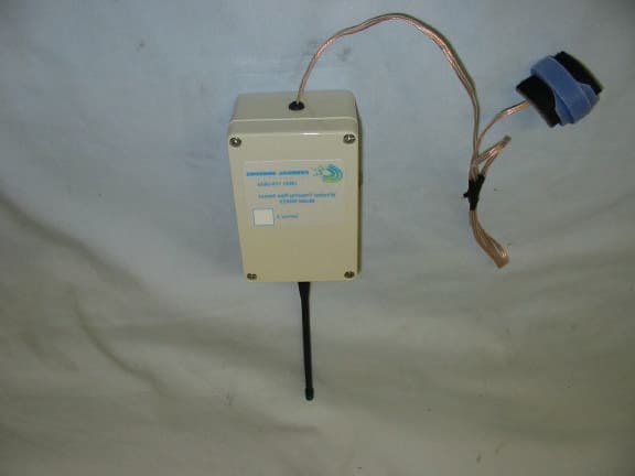
P72WIAS3
Jul 02, 2002Freezing Pipe Sensor
Equipment Class
DSC - Part 15 Security/Remote Control Transmitter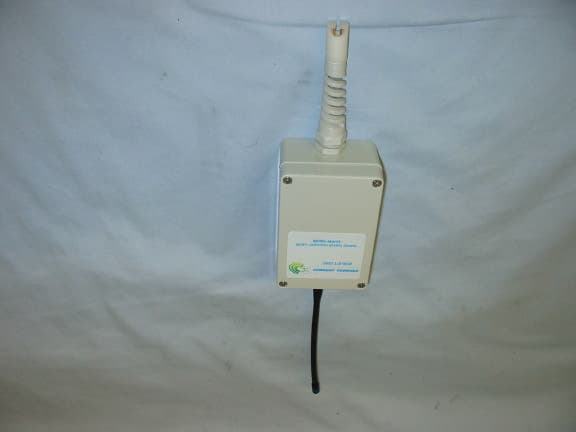
P72WIAS2
Jul 01, 2002Water Intrusion Sensor
Equipment Class
DSC - Part 15 Security/Remote Control Transmitter