P78525MO2002EL168Security/ Remote Control Trasmitter
Hang Zhou Mobile Electronics Co., Ltd.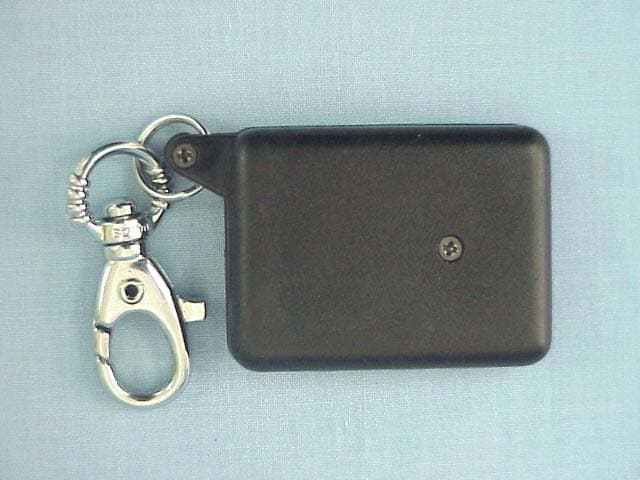
Click to zoom
Application Details
- Equipment Class
- DSC - Part 15 Security/Remote Control Transmitter
- Date of Grant
- Apr 07, 2002
- Application Purpose
- Original Equipment
- Date of Application
- Apr 07, 2002
- Equipment Note
- Security/ Remote Control Trasmitter
- Frequency Range
- 314.50000000 - 315.50000000
- Country
- China
Documents & Files
Document Text
Text extracted from the exhibit documents filed with the FCC. Open a document above to read the original.
Users Manual
User’s Manual Index System Contents Optional Accessories Features Alarm module-wiring diagram Door lock-wiring diagram Starter Disable Wiring Diagram Hardware Wiring Alarm Wiring Alarm programming Component Installation Anti-car jacking Transmitter Programming Testing & Operation Audible/Visual Status Indicators Programmable Feature Low voltage alarm Feature Note: Read This instruction manual thoroughly. Important: This unit is designed for a professional installation only! Any installation performed by an unqualified installer will VOID the warranty! System Contents Each System contains the following components: 1— Alarm Module 2— Transmitters 1—Siren 1— Shock Sensor 1— Main Wiring Harness 1—3 pin Door lock harness 1— Status LED 1— Push Button Valet Switch 1— Starter Disable Harness (3 Channel Model Only) 1---Anti jacket switch Optional Accessories Glass Break Sensor Radar Sensor Window Rollup Module Back Up Battery Siren Remote Car Starter Features Two small size 4-button remote controls with key chalan 150ft.minimurn transmitter operating range Remote panic function Door lock/unlock Door positive/negative triggers Trunk release output 3 rd channel output Defective Zone Alert/Defective Zone Bypass Last door Rearming Passive arming feature Separate dual stage shock sensor Status led Valet override switch 127dB 6-tone siren separated from main unit Starter disables output Built in relays Current sensing eirenit Anti-car jacking feature Programmable feature Transmitter code learning Warning sticker for window All mounting hardware to be included Emergency Override Switch Automatic Alarm Reset/Rearm Alarm Memory Keyless Entry in Valet Mode Flashing Parking Lights Output (Built in Relay) Low voltage alarm Hardware Wiring Siren Wiring Connect the Red siren wire to the Brown wire from the alarm control module. Connect the Black ground wire of the siren to the Black ground wire of the alarm unit or to the chassis ground. Dual Shock Sensor Wiring Using the shock sensor connector, plug the other end to the 4 pin connector on the PC board. LED Wiring: Plug the LED into the Red connector on the PC Board. Push Button Emergency override Switch Wiring: Plug the Emergency Override Switch into the Blue connector on the PC Board. Alarm Wiring Con’t White/black Stripe: Domelight Supervision –3 Channel Mode Only. Connect this White/Black Stripe wire to the common input or output for the domelight circuit. Orange: Stater Disable. 500 MA Negative Output When Armed. Connect this orange wire to pin 86 of the Starter Disable Relay. Grey: 2 nd Channel Output for Trunk Release 250 MA negative output when button #3 is pressed for 1.5 seconds. Green: Negative Door Switch Trigger Input (GM Type). Connect this Green wire to the door pin switch, which supplies negative (ground) when the door is opened. Blue: Negative Hood/Trunk Trigger Input. Connect this Blue wire to the Hood or Trunk negative trigger output. Violet :Positive Door Switch Trigger Input (Ford Type). Connect this violet wire to the door pin switch, which supplies positive +12 VDC when the door is opened. Brown :Siren + 12 V DC OUTPUT White: +12 VDC Output for Flashing Parking Lights. Connect the White wire to the positive side of the parking lights wire. Red: +12 VDC Main Power Source Input. Connect this Red wire to the positive terminal of the battery or to a constant +12 VDC main power source. The fuse must be installed at the battery end of the wire. Yellow: Switched +12 VDC Input. Connect this Ye l l o w wire to the ignition wire supplying +12 VDC when the ignition key is in the ignition “on”(run) position, This key switch position has +12 VDC only when the key is turned to the ignition “on”(run) position. When the car is running. Black wire to the chassis ground. White/Red Stripe: 3 rd Channel output –3 Channel Mode Only. 250 MA negative output when button #1 and #3 are pushed together for 2 seconds. Door Lock Harness Do not connect these doorlock wires directly to the power door lock motors. Green: Negative Door Lock Output( Lock pulse) Connect this Green wire to the lock wire of the door lock relay circuit. Blue: Negative Door Unlock Output (Unlock pulse) Connect this Blue wire to the unlock wire of the door lock relay circuit. Red: +12 VDC Constant Output. IMPORTANT: DO NOT CONNECT THIS RED WIRE DIRECTLY TO THE DOORLOCKMOTOR CIRCUIT Alarm Programming Dip Switch Programs: Switch # Function On Off Switch #1 Door Lock Pulse Timing .75 Sec. 3Sec. Switch #2 Door Lock Activation w/Ignition Yes No Switch #3 Door Lock w/Passive Arming Yes No Alarm Programming Con’t Dip Switch 1: Door Lock Timing (for use with Vacuum Door Lock Systems Only) Dip Switch 1 is in the “on” position: the door lock timing will be .75 second. Dip Switch 1 is in the “off” position: the door lock timing will be 3 seconds. Dip Switch 2: Ignition Auto Door Lock Dip Switch 2 is in the “on” position: the doors will lock automatically when the ignition is turned “on”, and unlock when the ignition is turned “off” (Default Setting). If a door is opened while the ignition is in the “on” position, the doors will not lock. Dip Switch 2 is in the “off” position: the doors will not lock automatically with ignition. Dip Switch 3: Passive Arm/Active Door Lock Dip Switch 3 is in the “on” position: the doors will lock automatically in passive arming mode. Dip switch 3 is in the “off” position: the doors will not lock automatically in passive arming mode. The doors will lock only when transmitter button number 1 is pressed. The Brown loop located inside the control module allows you to select Current or Switch Sensing mode. The system default is Switch Sensing Mode. To Activate Current Sensing Mode: Open the sliding door on the alarm system. Cut the Brown Loop located inside. The system is now programmed for Current Sensing. User Programmable Features-Transmitter Activated Transmitter Valet Mode Transmitter Chirp Delete Transmitter Sensor Delete Automatic Safety Rearm Quiet Arm/Disarm Mode Compon…
Text truncated - open the document above for the full version.
Block Diagram
Block Diagram Button Coding Circuit Encoder 2262 Circuit Signal Output Circuit Mixing and Amplifier Circuit Transmit Circuit
External Photos
FIGURE 1 CAR ALARM (TRANSMITTER) (M/N: RE-1) GENERAL APPEARANCE (FRONT SIDE) F IGURE 2 CAR ALARM (TRANSMITTER) (M/N: RE-1) GENERAL APPEARANCE (BACK SIDE)
ID Label/Location Info
Label Drawing Model: RE-1 FCC ID: P78525MO2002EL168 Factory: Hang Zhou Mobile Electronics CO., LTD Frequency Center: 315MHz Frequency Range: 0.5MHz Transmit Space: 25-35m Work Voltage: DC12V
ID Label/Location Info
Label Location Information Refer to the below red arrow: (for example)
Internal Photos
FIGURE 1 CAR ALARM (TRANSMITTER) (M/N: RE-1) COVER REMOVED FIGURE 2 CAR ALARM (TRANSMITTER) (M/N: RE-1) COMPONENT SIDE FIGURE 3 CAR ALARM (TRANSMITTER) (M/N: RE-1) SOLDERED SIDE
Operational Description
THE RE-1 OPERATION DESCRIPTION GENERAL: This device is used to control the car alarm into arm mode or disarm mode and other function. It consists of a car alarm module and a hand held control transmitter. They are four push buttons of the transmitter to operate the car alarm. the arm button is for arm the car alarm, the disarm button is for disarm the car alarm, the open trunk button is for control two channel output of the car alarm, the panic button is for panic the car alarm. An intemal twelve-volt alkaline battery provides power for the transmitter.(transmitter buttons position see diagram 1) The car alarm module has one thirteen connector for connect wiring to the car. the car alarm module obtains its power from the car battery +12VDC.the receiver module is consisting in car alarm module. The car alarm module will accept a total of 3 different transmitter codes. OPERATION: TRANSMITTER The hand-held remote is a 315Mhz transmitter with an output power of less then 10mW.the carrier is pulse modulated at 38kHz with a 25% duty cycle and contains status code and function data (12 bits/byte). when the four push buttons of the transmitter is depressed, the transmitter emits the code and data signal, which repcats every 42.24ms until the button is released. the purpose of the data is to send commands to control the car alarm module into arm mode or disarm mode and other function. The signal modulator(2262),with an internal clock of 100KHz produces the 12 bit modulator data (8 status+4 function).this chip work, drives an RF power transistor loaded with tuned antenna tank circuit. The antenna is etched onto the PC board. The transmitter can be set 8 bit status code input to the modulator, which can be manually set jump line on the PC board. A red LED is connected to the modulator to indicate the transmitter is working now. A single 12-volt battery supplies the power source for the transmitter. The circuit is protected from accidental reversed installation of the battery using IN4148 diode. The average current consumption of the unit in the transmit mode is 2.8mA. RECEIVER The receiver is a self-contained module consisting of car alarm module, a status LED, a push button valet switch, a main wiring harness. Car alarm module consisting of two PC boards, one is receive circuit, and other is main control board. The power supply from the car battery +12VDC. The +12VDC power source input are protected from the voltage by way of 15A fuse. The receiver board assembly is a two-stage, 315MHz, transistor receiver with tuned LRC circuits a dual OP amp (LM358) amplifies the signal. the antenna is a stiff 55cm black wire connected to the PC board. The board is connected to the main control board. The CPU on the main control board executes all functions when prompted by data received. A +12VDC voltage to the filtered (IN4007 diode, 220uF capacitor, 0.01uFcapacitor) to produce11.3VDC, the voltage regulator (MC78L05) connected to the 11.3VDC from a voltage-dropping resistor (47 ohms), supplies the 5VDC to the CPU circuit and the receive board assembly. The receiver current drain is 10mA DC.
Schematics
R63.3M R5100K Q1KSP10 D2 IN4148 D3 IN4148 D1LED C1103 C33.3P C4 C54.7P P3P4 B112V L1IuH VCC C23.3P D2IN4148 D3 IN4148 P1P2 VccEND A0A1A2A3A4A5A6A7 OUTA8A9A10A11CLK1CLK2 PT2262 12345678 9 1011121315161714 Schematics VCC R347K R447K R147K R247K R8150 R7470
Test Report
Hang Zhou Mobile Electronics Co., Ltd. FCC ID: P78525MO2002EL168 Page 1 of 21 Audix Technology (Shanghai) Co., Ltd. Report No: ACI-F02012 Prepared For : Hang Zhou Mobile Electronics Co., Ltd. 2F No.7 Bldg, Li Jia Qiao Industrial District, He Mu Zhi Rd, Hang Zhou Prepared By : Audix Technology (Shanghai) Co., Ltd. 3 F 34 Bldg 680 Guiping Rd, Caohejing Hi-Tech Park, Shanghai, China 200233 Tel : +86-21-64955500 Fax : +86-21-64955491 Report No. : ACI-F02012 Date of Test : Jan 28, 2002 Date of Report : Feb 26, 2002 Application for FCC Certification On behalf of Hang Zhou Mobile Electronics Co., Ltd. CAR ALARM (Transmitter) Model No.: RE-1 FCC ID: P78525MO2002EL168 Hang Zhou Mobile Electronics Co., Ltd. FCC ID: P78525MO2002EL168 Page 2 of 21 Audix Technology (Shanghai) Co., Ltd. Report No: ACI-F02012 TABLE OF CONTENTS Page 1 GENERAL INFORMATION.......................................................................................................... 4 1.1 Description of Equipment Under Test........................................................................................4 1.2 Description of Test Facility ........................................................................................................ 4 1.3 Measurement Uncertainty .......................................................................................................... 4 2 RADIATED EMISSION TEST....................................................................................................... 5 2.1 Test Equipment........................................................................................................................... 5 2.2 Block Diagram of Test Setup ..................................................................................................... 5 2.3 Radiated Emission Limit ............................................................................................................ 6 2.4 Test Configuration...................................................................................................................... 6 2.5 Operating Condition of EUT ...................................................................................................... 6 2.6 Test Procedures .......................................................................................................................... 6 2.7 Test Results ................................................................................................................................ 7 3 FUNDAMENTAL AND SPURIOUS EMISSIONS TEST ......................................................... 10 3.1 Test Equipment......................................................................................................................... 10 3.2 Block Diagram of Test Setup ................................................................................................... 10 3.3 Fundamental and Spurious Emission Limit ............................................................................. 10 3.4 Test Configuration.................................................................................................................... 10 3.5 Operating Condition of EUT .................................................................................................... 11 3.6 Test Procedures ........................................................................................................................ 11 3.7 Test Results .............................................................................................................................. 12 4 BANDWIDTH MEASUREMENT................................................................................................ 15 4.1 Test Equipment......................................................................................................................... 15 4.2 Bandwidth Limit....................................................................................................................... 15 4.3 Test Results .............................................................................................................................. 15 5 OPERATION DESCRIPTION ..................................................................................................... 16 APPENDIX I Plot of the Pulse Train........................................................................................... 17 APPENDIX II Plot of the Occupied Bandwidth......................................................................... 20 Hang Zhou Mobile Electronics Co., Ltd. FCC ID: P78525MO2002EL168 Page 3 of 21 Audix Technology (Shanghai) Co., Ltd. Report No: ACI-F02012 TEST REPORT FOR FCC CERTIFICATION Applicant : Hang Zhou Mobile Electronics Co., Ltd. Manufacturer : Hang Zhou Mobile Electronics Co., Ltd. EUT Description : CAR ALARM (Transmitter) (A) Model No.: RE-1 (B) Serial No.: N/A (C) Power Supply: DC 12V (D) Work Frequency: 315.8 MHz Test Procedure Used: FCC RULES AND REGULATIONS PART 15 SUBPART B & C MAY 2001 AND FCC/ANSI C63.4-1992 The device described above is tested by Audix Technology (Shanghai) Co., Ltd. to determine the maximum emission levels emanating from the device. The maximum emission levels are compared to the FCC Part 15 Subpart B & C limits. The test results are contained in this test report and Audix Technology (Shanghai) Co., Ltd. is assumed full responsibility for the accuracy and completeness of these measurements. Also, this report shows that the EUT to be technically compliant with the FCC official limits. This report applies to above tested sample only. This report shall not be reproduced in part without written approval of Audix Technology (Shanghai) Co., Ltd. This report must not be used by the applicant to claim product endorsement by NVLAP or any agency of the U.S. Government. Date of Test : Jan 28, 2002 Prepared by : Test Engineer : STELLA TANG (Assistant) SAMMY CHEN (Engineer) Reviewer : Approved Signatory : BYRON KWO (Supervisor) ALEX CHIU (Assistant Manager) Hang Zhou Mobile E…
Text truncated - open the document above for the full version.
Test Setup Photos
1. Radiated Emission Test (a) Attitude (Stand) HORIZONTAL VERTICAL (b) Attitude (Side) HORIZONTAL VERTICAL (c) Attitude (Lie) HORIZONTAL VERTICAL
Contact Information
Applicant
George Zhou(General Manager)
Test Firm
Audix Technology ( Shanghai ) Co., Ltd.Byron Kwo
Technical Specifications
| # | Rule Parts | Frequency Range | Power Output |
|---|---|---|---|
| 1 | 15.231 | 314.5 MHz - 315.5 MHz | - |