P7EHS-200WM001HS-200 Wireless Microphone
Daktronics, Inc.
Click to zoom
Application Details
- Equipment Class
- DXX - Part 15 Low Power Communication Device Transmitter
- Date of Grant
- Feb 13, 2002
- Application Purpose
- Original Equipment
- Date of Application
- Feb 13, 2002
- Equipment Note
- HS-200 Wireless Microphone
- Frequency Range
- 903.30000000 - 921.40000000
- Company
- Daktronics, Inc.
- Country
- United States
Documents & Files
Document Text
Text extracted from the exhibit documents filed with the FCC. Open a document above to read the original.
Users Manual
OmniSport ® is a registered trademark of Daktronics, Inc. ED12935 Product1056 Rev 4 – 13 February 2002 Copyright 1991, 2002 Daktronics, Inc. All rights reserved. While every precaution has been taken in the preparation of this manual, the publisher assumes no responsibility for errors or omissions. No part of this book covered by the copyrights hereon may be reproduced or copied in any form or by any means - graphic, electronic, or mechanical, including photocopying, taping, or information storage and retrieval systems - without written permission of the publisher. PO Box 5128 331 32 nd Ave Brookings SD 57006 Tel 605-697-4400 or 800-843-9879 Fax 605-697-4444 www.daktronics.com e-mail: [email protected] Horn Start HS-200 Operator’s Manual ED12935 Reproduction Reference ED12935 – P1056 Horn Start HS-200 Operators Manual 1. This page is for reproduction reference only and will not be included in the manual. 2. Copy this manual on FRONT AND BACK PAGES -8 ½ x 11 paper. Note: The first page, Cover Page, uses the front of the page (blank on back). Section heading pages always start on a new page; they never start on the back of another page. 3. Drawing included in this manual: A-23635 A-26797 A-150431 4. Use a blue window cover and a blue back. 5. Punch all pages, window cover, and manual back along the left edge and bind with a binder. 6. Please direct question and suggestions to Engineering Secretarial. Table of Contentsi Table of Contents Section 1:FCC Compliance Statement................................................................. 1-1 1.1HS-200 Wireless Microphone – FCC Compliance statement....................................1-1 Class A Device Statement..........................................................................................1-1 Section 2:Introduction............................................................................................... 2-1 2.1How To Use This Manual...........................................................................................2-1 Section 3:System Setup............................................................................................ 3-1 3.1System Setup..............................................................................................................3-1 Section 4:Operations................................................................................................. 4-1 4.1Operations...................................................................................................................4-1 4.2Battery Operation........................................................................................................4-1 4.3Changing the Horn Start Settings...............................................................................4-2 Section 5:System Storage......................................................................................... 5-1 5.1System Storage...........................................................................................................5-1 Section 6:Accessories............................................................................................... 6-1 6.1External Strobe Module..............................................................................................6-1 Battery Operation........................................................................................................6-1 AC Power Operation...................................................................................................6-1 6.2Wireless Microphone..................................................................................................6-2 HS-200 Wireless Microphone General Operation......................................................6-2 HS-200 Internal Wireless Module (IWM) General Operation...................................6-3 Section 7:Troubleshooting........................................................................................ 7-1 7.1Troubleshooting..........................................................................................................7-1 A speaker is not working............................................................................................7-1 The microphone is not working..................................................................................7-1 The strobe light does not work...................................................................................7-1 The recall tone does not sound...................................................................................7-1 The HS-200 will not turn on when attempting to run with battery power..................7-1 Noise Bursts when the Wireless Microphone is being used.......................................7-3 7.2Unit Exchange/Replacement Procedure.....................................................................7-3 Appendix A: Reference Drawings...................................................................................A-1 FCC Compliance Statement 1-1 Section 1: FCC Compliance Statement 1.1 HS-200 Wireless Microphone – FCC Compliance statement Class A Device Statement (Section 15.105(a) of the FCC Rules) Note: This equipment has been tested and found to comply with the limits for a Class A digital device, pursuant to part 15 of the FCC Rules. These limits are designed to provide reasonable protection against harmful interference when the equipment is operated in a commercial environment. This equipment generates, uses, and can radiate radio frequency energy and, if not installed and used in accordance with the instruction manual, may cause harmful interference to radio communications. Operation of this equipment in a residential area is likely to cause harmful interference in which case the user will be required to correct the interference at his/her own expense. Introduction 2-1 Section 2: Introduction 2.1 How To Use This Manual The Daktronics HS-200 Horn Start System uses the latest in electronic components to provide accurate starts…
Text truncated - open the document above for the full version.
Cover Letter(s)
SETTING NEW STANDARDS WORLDWIDE Message Centers • Time and Temperature Displays • Scoreboards For All Sports • Voting Systems Request for Confidential Treatment – HS-200 Wireless Microphone Daktronics Inc. requests that the schematic diagram included as a requirement specified by Section 2.1033(b)(5) of FCC rules be withheld from public disclosure in accordance with Section 0.457 and 0.459 of the Commission’s Rules, 47 C.F.R., following grant of the FCC ID application. In support of this request, Daktronics submits the following: 1) Identification of the specific information for which confidential treatment is sought The HS-200 Wireless Microphone schematic diagram, included as a requirement for Section 2.1033(b)(5), is that for which confidentiality is sought. 2) Identification of the Commission proceeding in which the information was submitted or a description of the circumstances giving rise to the submission: The proceeding is that involving the application for equipment authorization (certification) and FCC ID number assigment for the HS-200 Wireless Microphone. 3) Explanation of the degree to which the information is commercial or financial, or contains a trade secret or is privileged: This schematic diagram includes the results of design and testing engineering effort that was sponsored by Daktronics, Inc, and is therefore is considered confidential. 4) Explanation of the degree to which the information concerns a service that is subject to competition: This product could possibly be used in a similar system designed by a scoring and timing or other Daktronics competitor. 5) Explanation of how disclosure of the information could result in substantial competitive harm: Disclosure of the schematic diagrams would in effect give away Daktronics intellectual property to competitors. This would give competitors an unfair advantage in the expenditure of engineering and other development cost, as well as time to market of a similar design. DAKTRONICS, INC. 331 THIRTY-SECOND AVENUEFAX 605/697/4444 POST OFFICE BOX 5128TOLL FREE 800/843/9879 BROOKINGS, SOUTH DAKOTA 57006-5128 U.S.A.TELEPHONE 605/697/4400 SETTING NEW STANDARDS WORLDWIDE Message Centers • Time and Temperature Displays • Scoreboards For All Sports • Voting Systems 6) Identification of any measures taken by the submitting party to prevent unauthorized disclosure: All schematic information and other intellectual property at Daktronics is strictly confidential, and accessible only to other employees or authorized persons who have signed non-disclosure agreements. 7) Identification of whether the information is available to the public and the extent of any previous disclosure of the information to third parties: To the knowledge of those preparing this application, no schematic diagram of the Daktronics Wireless Microphone has been released in any type of public setting. 8) Justification of the period during which the submitting party asserts the material should not be available for public disclosure: We request that material should not be disclosed for at least 20 years. Daktronics is committed to supporting its products for extended period of time. While design enhancements may be made during this time, a release of this material would reveal the knowledge gained as a result of Daktronics investment in hours of labor, engineering and other, and give competitors and unfair advantage as asserted in (5.) The release of this information would also violate company policy as asserted in (6.) Randy Uehran Product Engineer Daktronics Inc.
External Photos
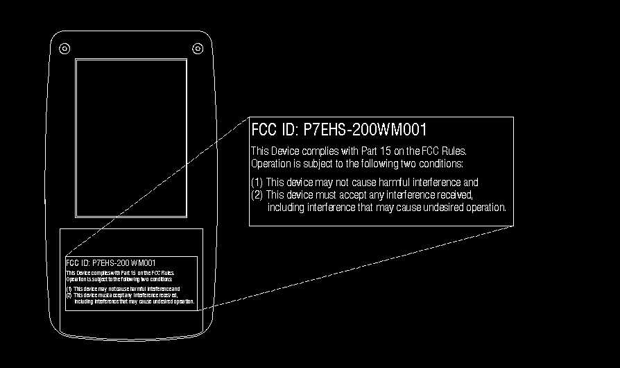
A FCC ID: P7EHS-200WM001Report No:3019125 – February, 2002 Page 58 of 65 External Photo A FCC ID: P7EHS-200WM001Report No:3019125 – February, 2002 Page 59 of 65 External Photo
Internal Photos
A FCC ID: P7EHS-200WM001Report No:3019125 – February, 2002 Page 61 of 65 Internal Photo A FCC ID: P7EHS-200WM001Report No:3019125 – February, 2002 Page 62 of 65 Internal Photo A FCC ID: P7EHS-200WM001Report No:3019125 – February, 2002 Page 63 of 65 Internal Photo
Operational Description
HS-200 Wireless Microphone Theory of Operation The HS-200 Wireless Microphone uses an OEM RF module and PCB mount antenna to transmit both voice and data signals to the HS-200 receiver. This device is used as a PA and starting system for swimming, track and other applications. A modified CB microphone controls the unit. When the side button on the microphone is pressed, a digital signal is sent to the receiver, turning the audio circuits on. Any voice picked up by the microphone while the side button is pressed is transmitted to the receiver. When the top button on the CB microphone is pressed, a digital signal is transmitted to the receiver, which produces an audible tone.
Test Report
A Daktronics Inc. Application For Certification Transmitter Model HS-200 Wireless Mic (FCC ID: P7EHS-200WM001) February 11, 2002 All services undertaken are subject to the following general policy: Reports are submitted for exclusive use of the client to whom they are addressed. Their significance is subject to the adequacy and representative character of the samples and to the comprehensiveness of the tests, examinations or surveys made. No quotations from reports or use of Intertek Testing Services name is permitted except as expressly authorized by Intertek Testing Services in writing. The report must not be used by the client to claim product endorsement by NVLAP or any agency of the U.S. Government. The NVLAP logo is applicable for testing to I EC/CISPR 22:1993 and FCC-47 CFR part 15 only. A TABLE OF CONTENTS 1.0General Description............................................................................................1 1.1Related Submittal(s) Grants ..........................................................................1 1.2Product Description ...................................................................................1 1.3Test Methodology .....................................................................................2 1.4Test Facility ............................................................................................2 2.0System Test Configuration...................................................................................3 2.1Justification .............................................................................................3 2.2EUT Exercising Software ............................................................................3 2.3Special Accessories....................................................................................3 2.4Equipment Modification ..............................................................................3 2.5Support Equipment List and Description ..........................................................3 2.6Test Configuration Block Diagram .................................................................4 3.0Test Results......................................................................................................5 3.1Field Strength of Fundamental and Harmonics Emissions .....................................6 3.2Out of Band Spurious Emissions.................................................................. 46 3.3Field Strength Calculation.......................................................................... 50 4.0Test Equipment............................................................................................... 51 EXHIBIT I Test Set Up Photographs ..................................................................................... 52 EXHIBIT II FCC ID Label Location ...................................................................................... 56 EXHIBIT III External Photographs ......................................................................................... 57 EXHIBIT IV Internal Photographs .......................................................................................... 60 EXHIBIT V Electrical Schematics and Block Diagram................................................................. 64 EXHIBIT VI User Manual and Operational Description ................................................................ 65 A FCC ID: P7EHS-200WM001Report No:3019125 – February, 2002 Page 1 of 65 1.0 GENERAL DESCRIPTION 1.1 Related Submittals Grants This is single application of the HS-200 Wireless Mic for Certification under Part 15 Subpart C. There are no other simultaneous applications . 1.2 Product Description Purpose of the IT2611 RF Module The HS-200 Wireless Mic is a part of the HS-200 Start System. The HS-200 Wireless Mic is a hand-held transmitter with an attached antenna. The intended use of the HS-200 Wireless Mic unit is to generate and transmit both voice and data signals upon command from an attached modified CB Microphone. When the side button on the microphone is pressed, a digital signal is sent to receiver, turning the audio circuits on, and any voice picked up by the microphone is transmitted to receiver. When the top button on the CB microphone is pressed, a digital is transmitted to receiver. The HS-200 Wireless Mic powered at 3VDC from two internal AA-size batteries. The HS-200 Wireless Mic Transmitter The HS-200 Wireless Mic Transmitter operates in frequency range: From 903.37 to 921.37MHz (FM/FSK Modulation Method), adjustable in eight channels from channel 0 to channel 7. The HS-200 Wireless Mic Antenna The antenna on the HS-200 Wireless Mic is a PCB mounted, internal to the chassis and is not easily accessible. A FCC ID: P7EHS-200WM001Report No:3019125 – February, 2002 Page 2 of 65 1.3Test Methodology Emission measurements were performed according to the procedures in ANSI C63.4-1992. All field strength radiated emissions measurements were performed in the semi-anechoic chamber, and for each scan, the procedure for maximizing emissions in Appendices D and E were followed. All field strength radiated tests were performed at an antenna to EUT distance of 3 meters, unless stated otherwise in the "Justification Section" of this Application. 1.4Test Facility The test site facility used to collect the radiated and conducted measurement data is located at 7250 Hudson Blvd., Suite 100, Oakdale, Minnesota. This test facility has been fully described in a report dated on January 2000 submitted to your office. Please reference the site registration number: 90706, dated May 19, 2000. A FCC ID: P7EHS-200WM001Report No:3019125 – February, 2002 Page 3 of 65 2.0SYSTEM TEST CONFIGURATION 2.1Justification The EUT was powered at 3VDC from two AA-size fresh batteries. The EUT was set up as tabletop equipment. 2.2EUT Exercising Software The HS-200 Wireless Mic was tested in the continuous transmission mode. 2.3Special Accessories There are no special accessories necessar…
Text truncated - open the document above for the full version.
Test Setup Photos
A FCC ID: P7EHS-200WM001Report No:3019125 – February, 2002 Page 53 of 65 Radiated Emissions Test Configuration A FCC ID: P7EHS-200WM001Report No:3019125 – February, 2002 Page 54 of 65 Radiated Emissions Test Configuration A FCC ID: P7EHS-200WM001Report No:3019125 – February, 2002 Page 55 of 65 Radiated Emissions Test Configuration
Contact Information
Applicant
Randy Uehran(Product Engineer)
Technical Contact
Daktronics, Inc.Dan Walkes
[email protected]605-697-4687
331 32nd Avenue · Brookings, South Dakota · United States
Non-Technical Contact
Intertek Testing Services NA Inc.Yuriy Litvinov
[email protected]651-730-1188
Test Firm
Intertek Testing ServicesUri Spector
Technical Specifications
| # | Rule Parts | Frequency Range | Power Output |
|---|---|---|---|
| 1 | 15C | 903.3 MHz - 921.4 MHz | - |