P7YSDIWD101
Shearwater Digital Innovations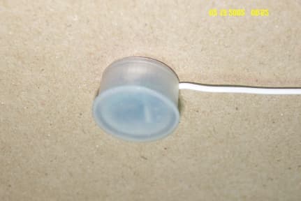
Click to zoom
Application Details
- Equipment Class
- DSC - Part 15 Security/Remote Control Transmitter
- Date of Grant
- Sep 02, 2002
- Application Purpose
- Original Equipment
- Date of Application
- Feb 26, 2002
- Frequency Range
- 319.50000000 - 319.50000000
- Country
- United States
Documents & Files
Document Text
Text extracted from the exhibit documents filed with the FCC. Open a document above to read the original.
Users Manual
Shearwater Digital Innovations – Installation Guide 1 Embedded Window Frame Security Sensor Installation Instructions The Embedded Window Frame Sensor/Transmitter detects when a window is closed or opened, and transmits a wireless security message to the System Control Panel. This is accomplished through the use of a sensor unit (which contains the wireless transmitter and battery), and magnet unit. When the two are separated, by opening the window, the sensor transmits an OPEN signal to the System Control Panel. When the window is shut, the magnet is again within the sensor's range, and a CLOSE signal is sent. Fig 1: Sensor and Magnet The sensor sends supervisory signals to the panel every 64 minutes (approximately). The sensor is powered by a 3.0V, lithium battery, model CR1632. The sensor has been designed to draw very little power when in standby mode, and the CR2032 battery should last up to 10 years typically. The battery should be replaced by the installer only, as to do so the entire package needs to be removed from the window frame. Required Tools for Installation ! Electric Drill ! SDI Custom Frame Drill Bit ! Pencil or chalk ! Installation Sheet for documenting sensor locations Guidelines The following guidelines will help ensure that installations are safe and efficient. ! A sensor can be mounted on any side of the window frame (top, side, or bottom), such that the opening of the window moves the magnet away from the sensor. ! Always try to mount the hardware such that the magnet, not the sensor, is in the moving window panel. The sensor can be installed in the moving window panel, but should be avoided. ! Do not install the sensor in the frame until after the panel has “learned” the sensor’s unique code (see LEARN SENSORS). ! Sensor’s should be kept as close to the panel or repeater as possible. Try to chose locations where the separation is within 100 ft. ! Avoid mounting the sensor in a location where it will be exposed to moisture. ! Avoid mounting a sensor where temperatures are excessively hot or cold. ! This device cannot be mounted in a metal frame, as the frame will block the antenna (there is an external version of this device that will fit on the exterior of an aluminum frame). ! WARNING: Some installations may have electrical wiring running through the door or window frames. Use caution to avoid electrical shocks . Magnet Sensor & Antenna Shearwater Digital Innovations – Installation Guide 2 Preparation 1. Determine a suitable location for the sensor and the magnet. These units are meant to be mounted inside the frame of the window. As such do not drill a mounting hole unless: • You are a qualified installer • There is sufficient room for the devices in the frame and window (Not all windows may have the necessary clearance). • You have read, and are familiar with the mounting instructions for the sensor and magnet (specifically the orientation required – see diagram included) • You have the custom drill bit to allow proper mounting of the sensor and magnet in the frame. 2. Measure and mark where the sensor and magnet will be installed in the window frame. Use the guide provided in Fig 2 for the location of the two holes. The magnet and the sensor need to be offset for correct performance. 3. Always ensure that the magnet is mounted on the side that the opening will occur on. Do not mount the magnet such that it has to travel over the sensor before it moves away from the sensor (Fig. 3). 4. Measure the distance between the window panel and frame. Ensure the separation is no more than 0.75” in height. Note: In cases where the separation may be greater, a larger magnet may be required. Contact the manufacturer for alternate magnets. 5. Verify the sensor will operate properly with the control panel, prior to drilling any holes. Go to the next section, LEARN SENSORS. Fig 2. Correct Positioning the Magnet and the Sensor relative to each other Sensor in Frame Magnet in Window Panel 1.000”+/-.200” Direction of Window Movement, away from sensor Direction of Window Movement, away from sensor. Left, Up, or Out of Page Shearwater Digital Innovations – Installation Guide 3 Fig 3: Incorrect Orientation of Magnet and Sensor Direction of Window Movement, magnet moves over and past sensor. Shearwater Digital Innovations – Installation Guide 4 Learn Sensors The sensors need to be added to the control panel memory (learned). This is done by triggering the sensor in it’s “Learn Mode” while the panel is setup to record it. Refer to your panel installation instructions or reference manual for complete details. 1. Set the panel to Program Mode. 2. Proceed to the LEARN SENSORS menu. 3. Select the appropriate sensor group and sensor number. 4. Trip the sensor. This is done simply by inserting the battery in it’s battery clip. When the device powers on, it will send out a “Learn” signal to the panel. 5. After verifying that the panel recognized the sensor, place it back in it’s plastic package, ensuring the antenna is lined up with the slot on the side of the plastic dowel. Ensure the cap is lined up so the wire antenna exits the small hole on the bottom, and snap the cap back on. (note: the square opening is used to remove the cap when replacing the battery). 6. Repeat this with all the sensor’s being installed. 7. Exit Program Mode. Fig 4. Dowel Package, Dowel Lid, Sensor Electronics (including battery) Fig. 5: Assembled Sensor Shearwater Digital Innovations – Installation Guide 5 Installation in Window Frame 1. Using the dealer provided window frame bit supplied with your dealer kit, drill a ¾” hole in the frame for the sensor, and one in the window panel for the magnet. 2. Both the sensor and the magnet have ribs on the outside that will provide a bite fit into the frame. First insert the wire into the inside of the frame, through the hole just drilled. Slowly press the sensor into the window frame until it’s lid is flush with the frame base. 3. The dealer has the option of using a sea…
Text truncated - open the document above for the full version.
Cover Letter(s)
July 29, 2002 Federal Communications Commission Dear Sir or Madam: We request that for the transmitter submissions, FCC ID: P7YSDIWD101, FCC ID: P7YSDIDD101, and FCC ID: P7YSDIFP101, the following infor mation be held confidential: Schematic Block Diagram Bill of Materials Sincerely, Dean Schebel Partner - Engineering SHEARWATER DIGITAL INNOVATIONS 9054 SHEARWATER ROAD • BLAINE, WA • 98230-5700 PHONE: 1-800-407-4389 • FAX: 1-800-407-4465
External Photos
EMC Compatibility Report Rev.1.0 02/15/02 Shearwater Digital Innovations Page 1 of 3Emission Test Record SDIWD-101Appendix H External Photos Appendix H: External Photos: Front view of the Test Setup EMC Compatibility Report Rev.1.0 02/15/02 Shearwater Digital Innovations Page 2 of 3Emission Test Record SDIWD-101Appendix H External Photos Rear view of the Test Setup EMC Compatibility Report Rev.1.0 02/15/02 Shearwater Digital Innovations Page 3 of 3Emission Test Record SDIWD-101Appendix H External Photos SDIWD-101 SDIWD-101
ID Label/Location Info
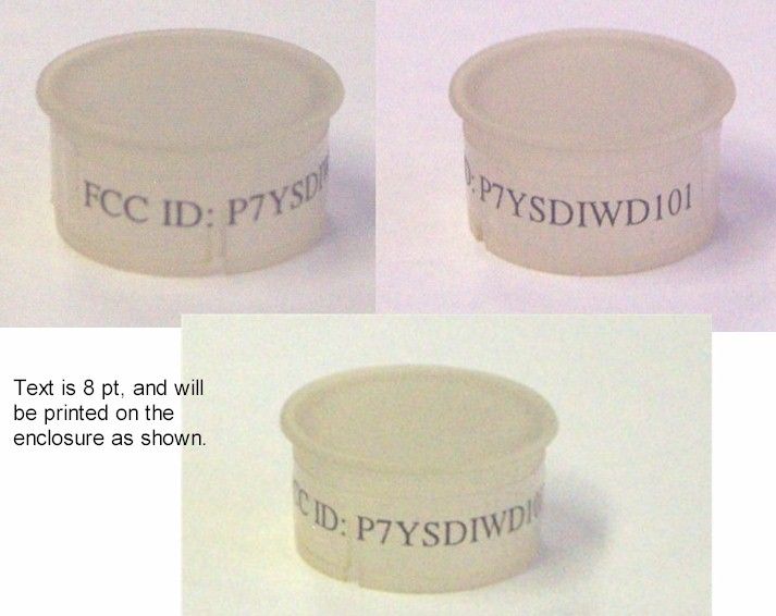
The following FCC identifier drawings are based on drawings rather than completed packages, which are in the process of being molded at this time. Window Dowel - Text is 8 point, engravedFlat Package – Text is 8 Point, engraved inside lid on cap. Door Dowel Package – Text is 8 point, engraved on bottom of package.
ID Label/Location Info
The following FCC identifier drawings are based on drawings rather than completed packages, which are in the process of being molded at this time. Window Dowel - Text is 8 point, engravedFlat Package – Text is 8 Point, engraved inside lid on cap. Door Dowel Package – Text is 8 point, engraved on bottom of package.
ID Label/Location Info
The following FCC identifier drawings are based on drawings rather than completed packages, which are in the process of being molded at this time. Window Dowel - Text is 8 point, engraved on cap.
ID Label/Location Info
FCC Label for the P7YSDIWD101
ID Label/Location Info
The following FCC identifier drawings are based on drawings rather than completed packages, which are in the process of being molded at this time. Window Dowel - Text is 7 point, engravedFlat Package – Text is 8 Point, engraved inside lid on cap. Door Dowel Package – Text is 7 point, engraved on bottom of package.
Internal Photos
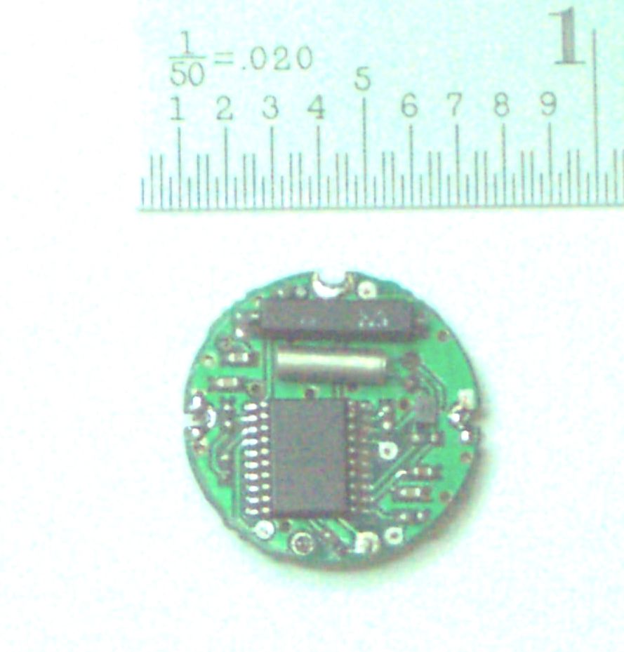
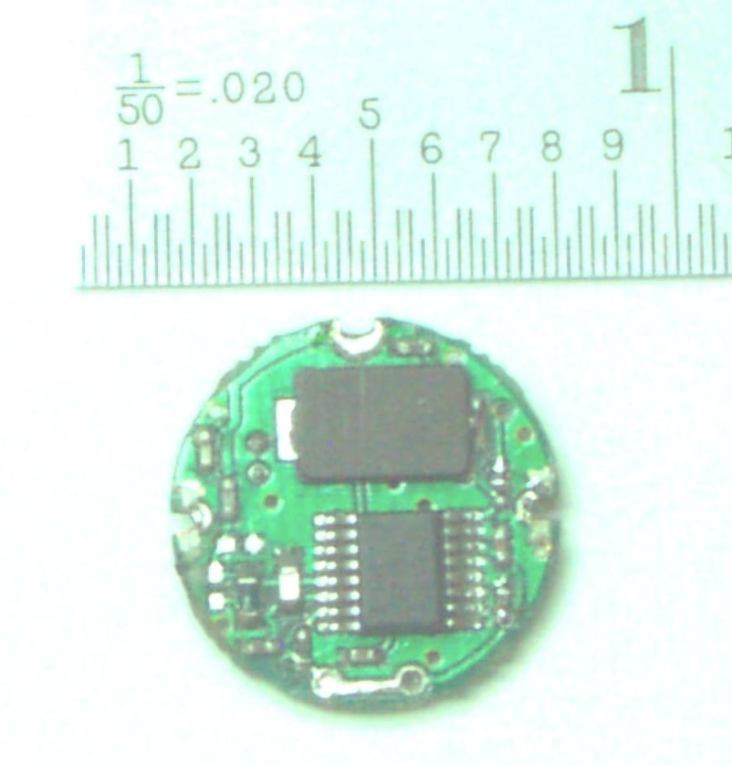
EMC Compatibility Report Rev.1.0 02/15/02 Shearwater Digital Innovations Page 1 of 2Emission Test Record SDIWD-101Appendix G Internal Photos Appendix G: Internal Photos: Battery Side of the SDIWD-101 EMC Compatibility Report Rev.1.0 02/15/02 Shearwater Digital Innovations Page 2 of 2Emission Test Record SDIWD-101Appendix G Internal Photos Battery Side of the SDIWD-101 Component Side Of The SDIWD-101
Test Report
EMC Compatibility Report Rev 1. 0 02/15/02 Shearwater Digital Innovations Page 1 of 6 Emission Test Record SDIWD-101 Test Report Shearwater Digital Innovations SDIWD-101 FCC CFR47 Part 15 Report of Measurements Revision 1.0 February 15, 2002 Approvals Written By ___________________________________________________ Craig LongDate Checked by ___________________________________________________ Robert Stirling, P. Eng.Date Protocol Labs, Abbottsford B.C., Canada FCC Registration Number 96437 Industry Canada Registration Number IC3384 EMC Compatibility Report Rev 1. 0 02/15/02 Shearwater Digital Innovations Page 2 of 6 Emission Test Record SDIWD-101 Test Report Index of Submitted Measured Data Index2 Testing Details3 Equipment Under Test 3 Graphs and Data Appendix A Table 1, Figure 1 319.50 MHz Harmonics5 Figure 2 Occupied Bandwidth6 Photographs Appendix B: Test Setup Photos Schematics Appendix C: EUT Schematics PC Board Layout Appendix D: EUT PC Board Layout Bill of Materials Appendix E: Bill of Materials Waveforms Appendix F: Waveforms Internal Photos Appendix G: Internal Photos External Photos Appendix H: External Photos EMC Compatibility Report Rev 1. 0 02/15/02 Shearwater Digital Innovations Page 3 of 6 Emission Test Record SDIWD-101 Test Report CE Mark EMC Directive Compliance Test Report FCC CFR47 PART 15 Report of Measurements Testing Details TEST DATE:December 21, 2001 TESTED BY: Rob Stirling/ Craig Long TEST CONDITIONS:Temperature and Humidity: 18 C, 35% TEST VOLTAGE: 3 Vdc Test Facilities Protocol Labs 28945 McTavish Rd. Abbotsford B.C., Canada, V4X 2E7 FCC Registration Number 96437 Industry Canada Registration Number IC3384 Test Equipment List: DeviceModel NumberSerial No.Last Cal.Next Cal AntennaEMCO 3141 Bilog Antenna112709/13/0109/13/02 HornEMCO 31405 Horn Antenna202409/10/0109/10/02 AmpHewlett Packard 8349A2512A0082409/13/0109/13/02 LISNSolar 8012-50-R-24-BNC86309202/20/0102/20/02 Spectrum Analyzer Hewlett Packard 8566B2241A0210212/28/0012/28/01 RF-PreselectorHewlett Packard 85685A3107A0122212/28/0012/28/01 Quasi-Peak Adapter Hewlett Packard 85650A2043A0024012/28/0012/28/01 TowerRhientech LabsCustom TurntableProtocolCustom Equipment Under Test: EUTWindow Dowel RF Security Monitor Manufacturer Shearwater Digital Innovations Model NumberSDIWD-101 Serial NumberENG001 SETUP:The equipment was set up in an open field test site. All harmonic measurements were made at a 3-meter open field test site. Peak spurious Emissions in both horizontal and vertical polarizations were measured based on continuous modulated signal while rotating the EUT on a turntable to maximize the emissions signal strength and the results recorded on the attached tables and plots. Average emissions are based on actual duty cycles pulsed and modulated signal as in Appendix F. Refer to Photographs in Appendix A. CABLING: EMC Compatibility Report Rev 1. 0 02/15/02 Shearwater Digital Innovations Page 4 of 6 Emission Test Record SDIWD-101 Test Report CableConnectorLoad/Termination? N/AN/AN/A TEST FIRMWARE:Continuous Modulated output. TEST DATA: Refer to Appendix B for Graphs and Test Results. CONCLUSION: The EUT complies with the requirements of FCC Part 15. Appendix B: Measurement Data: EMC Compatibility Report Rev 1. 0 02/15/02 Shearwater Digital Innovations Page 5 of 6 Emission Test Record SDIWD-101 Test Report Spurious Emissions Harmonics of 319.500 MHz Figure 1 319.5 MHz Harmonics Harmonic Frequency (MHz) +/- 0.005 Polarity Uncor Pk (dBuV) +/- 0.05 Tot Corr (dB) +/- 0.05 Peak (dBuV/m) +/- 0.05 Average (dBuV/m) +/- 0.05 Limit (dBuV/m) +/- 0.05 Delta Lim (dB) +/- 0.05 1st319.50V77.73.280.970.975.9-5.0 2nd639.00V53.214.767.957.961.9-4.0 3rd958.50V41.619.160.750.761.9-11.2 4th1278.00V27.222.349.539.561.9-22.4 5th1597.50V15.924.940.830.861.9-31.1 6th1917.00V14.528.142.632.661.9-29.3 7th2236.50V57.2-6.151.141.161.9-20.8 8th2556.00V46.4-3.542.932.961.9-29.0 9th2875.50H43.3-0.742.632.661.9-29.3 10th3195.00V17.21.919.19.161.9-52.8 Average Radiated Spurious Emissions 57.92 50.74 39.45 30.77 32.63 41.07 32.87 32.59 9.11 70.91 0.000 10.000 20.000 30.000 40.000 50.000 60.000 70.000 80.000 90.000 100.000 110.000 120.000 130.000 140.000 1st2nd3rd4th5th6th7th8th9th10th Fundamental and Harmonics Field Strength (dBuV/m) EMC Compatibility Report Rev 1. 0 02/15/02 Shearwater Digital Innovations Page 6 of 6 Emission Test Record SDIWD-101 Test Report Figure 2 Occupied Bandwidth
Test Report
EMC Compatibility Report Rev.1.0 05/23/02 Shearwater Digital Innovations Page 1 of 1Emission Test Record SDIWD-101Appendix B Data Appendix B: Measurement Data: The attached updated Appendix reflects the re-measured emissions for the 2 nd harmonic (638 MHz) of the EUT at 3 meters. The EUT was re-measured using a production battery clip, as illustrated in the original submission, but which was only mocked up in the test sample used in the original measurements submitted in February and March. The readings discrepancies were verified by comparative measurements, and all other spurious emissions were found to be reduced somewhat as well. Spurious Emissions Harmonics of 319.500 MHz Harmonic Frequency (MHz) +/- 0.005 Polarity Uncor Pk (dBuV) +/- 0.05 Tot Corr (dB) +/- 0.05 Peak (dBuV/m) +/- 0.05 Average (dBuV/m) +/- 0.05 Limit (dBuV/m) +/- 0.05 Delta Lim (dB) +/- 0.05 1st319.50V77.73.280.970.975.9-5.0 2nd639.00V35.824.360.150.155.0-4.9 3rd958.50V41.619.160.750.755.0-4.3 4th1278.00V27.222.349.539.555.0-15.5 5th1597.50V15.924.940.830.855.0-24.2 6th1917.00V14.528.142.632.655.0-22.4 7th2236.50V57.2-6.151.141.155.0-13.9 8th2556.00V46.4-3.542.932.955.0-22.1 9th2875.50H43.3-0.742.632.655.0-22.4 10th3195.00V17.21.919.19.155.0-45.9 Average Radiated Spurious Emissions 50.10 50.74 39.45 30.77 32.63 41.07 32.87 32.59 9.11 70.91 0.000 10.000 20.000 30.000 40.000 50.000 60.000 70.000 80.000 90.000 100.000 110.000 120.000 130.000 140.000 1st2nd3rd4th5th6th7th8th9th10th Fundamental and Harmonics Field Strength (dBuV/m)
Test Setup Photos
EMC Compatibility Report Rev.1.0 02/15/02 Shearwater Digital Innovations Page 1 of 2Emission Test Record SDIWD-101Appendix B Test setup Photos Appendix B: Photos: Front view of the Test Setup EMC Compatibility Report Rev.1.0 02/15/02 Shearwater Digital Innovations Page 2 of 2Emission Test Record SDIWD-101Appendix B Test setup Photos Rear view of the Test Setup
Contact Information
Applicant
Dean Schebel(V.P. Engineering)
Technical Contact
Non-Technical Contact
Protocol LabsCraig R Long
[email protected]604-607-0012
Test Firm
Protocol LabsRobert Stirling
Technical Specifications
| # | Rule Parts | Frequency Range | Power Output | Tolerance |
|---|---|---|---|---|
| 1 | 15C | 319.5 MHz - 319.5 MHz | - | % |
Other Applications from Shearwater Digital Innovations
P7YSDIDD101
Oct 28, 2002Door dowel security sensor RF transmitter
Equipment Class
DSC - Part 15 Security/Remote Control Transmitter
P7YSDIFP101
Jul 31, 2002Flat Pack Window/ door security sensor RF Transmit
Equipment Class
DSC - Part 15 Security/Remote Control Transmitter