P7Z440914AHandheld Data Transceiver
ABB POWER TECHNOLOGY PRODUCTS AB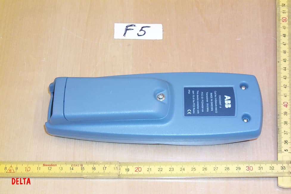
Click to zoom
Application Details
- Equipment Class
- DXT - Part 15 Low Power Transceiver, Rx Verified
- Date of Grant
- Jun 09, 2002
- Application Purpose
- Original Equipment
- Date of Application
- Jun 09, 2002
- Equipment Note
- Handheld Data Transceiver
- Frequency Range
- 916.50000000 - 916.50000000
- Country
- Sweden
Documents & Files
Document Text
Text extracted from the exhibit documents filed with the FCC. Open a document above to read the original.
Users Manual
1 2501en EXCOUNT-II Users Manual Users manual EXCOUNT-II 2 2501en EXCOUNT-II Users Manual Legal disclaimer Any responsibility or liability for loss or damage in connection with the use of this product and the accompanying documentation is disclaimed. The information in this document is furnished for informational use only, is subject to change without notice, may contain errors or inaccuracies, and represents no commitment whatsoever. Federal Communications Commission Statement This device complies with part 15 of the FCC Rules. Operation is subject to the following two conditions: (1) this device may not cause harmful interference, and (2) this device must accept any interference received, including interfe- rence that may cause undesired operation. WARNING! Any changes or modifications to this product not expressly approved by the manufacturer could void any assurances of safety or performance and could result in violation of Part 15 of the FCC Rules. Trademark acknowledgements Windows 95, 98, ME, NT4 and 2000 are registred trademarks of Microsoft Corporation. Safety instructions Do not connect the Transceiver to other voltage sources than a standard 9 volt battery type 6LR61/PP3 Ensure that the battery is connected correctly. The Transceiver contains a radio transmitter and receiver which must not be used where the use of radio transmitters or other electronic devices is prohibited. WARNING! All work related to the EXCOUNT-II ́s sensors and the surge arresters shall be made with disconnected and earthed conductors. Follow all regulations and rules stated by international or national safety regula- tions. Normally, the EXCOUNT-II ́s sensors and the surge arresters operate at a high voltage. Therefore they must be installed in such a way that only qualified personnel has access to them. 3 2501en EXCOUNT-II Users Manual EXCOUNT-II is an advanced surge arrester monitor for effectively, reliably and safety monitoring and recording surges on high voltage electrical networks. EXCOUNT-II incorporates a sensor, which is mounted on the surge arrester, a transceiver, for remote reading and a PC-program (Windows 95/98/2000/ME and NT). This users manual desribes the functions of EXCOUNT-II to give you total control over surge monitoring. Table of contents 1. Using the transceiver Description of the buttons 4 Normal maintenance 4 2. Getting started First time usage 5 Installation/uninstallation of software 5 Administration of sensors 6 3. Flowchart, make measurements 7 4. Transceiver symbols 8 5. Transceiver menu system 9 6. Transceiver error codes 14 8. Sensor installation 16 9. More information 19 Introduction 4 2501en EXCOUNT-II Users Manual Enter Increase value Display screen Decrease value Move down Move up Go back NOTE! To turn on the transceiver press To turn off the transceiver press Normal maintenance To achieve the best possible lifetime out of your EXCOUNT-II Transceiver, avoid exposure to strong sunlight for extended periods, hot temperatures (over +50 º C), cold temperatures (under -10 º C ) and water (the design is showerproof but not watertight). To clean the transceiver use only a damp soft cloth with a mild detergent. Using the transceiver 5 2501en EXCOUNT-II Users Manual Getting started First time usage Open the package and verify that the following items are present together with this manual: Transceiver Data cable (RS232) CD with software Familiarize yourself with the above safety instructions. Fit a new 9 volt battery type 6LR61/PP3. Press the button on the front panel and verify that the transceiver powers up and that the stand-by menu appears. Press the button and verify that the transceiver powers down. Using this manual together with the transceiver and familiarize yourself with the different menus and how they are used. Particulary ensure that the date and clock on the Transceiver are set correctly. Load the EXCOUNT-II software onto your PC and famliarize yourself with its use by reading the individual HELP files within each respective section. Installation/unistallation of software Installation of software Insert the CD into your computer. Press the START button in lower left corner Select SETTINGS then CONTROL PANEL Double-click on the icon ADD/REMOVE PROGRAMS Select ADD NEW PROGRAMS Follow the instructions on the screen Uninstalling of software Press the START button in lower left corner Select SETTINGS then CONTROL PANEL Double-click on the icon ADD/REMOVE PROGRAMS Browse to the EXCOUNT-II software and click REMOVE 6 2501en EXCOUNT-II Users Manual Administration of Sensors Fit the sensor to the arrester as described in the installation instructions supplied with it. Record the following details as specified in the EXCOUNT-II HELP system for administration: station data arrester data EXCOUNT-II data Input this data into the software as described in the HELP system. IMPORTANT! After installation of a new sensor and input of the adminis- tration details, an initial reading must always be made to establish a link between the administration details in the PC software and the sensor on site. Connect the transceiver to the PC via the data cable Download the sensor’s ID from the EXCOUNT-II software into the Transcei- ver. IMPORTANT! Check that the date and time on the Transceiver are correct, otherwise set them as described in this manual. Note! If this is not done the date stamp from the sensor will be incorrect. Before going to site, check the Transceiver’s battery status. If necessary, install a new battery. Once at site, individually check that it is possible to make contact with each sensor. This is most easily done by taking a leakage current mea- surement as described in this manual. If the sensor is not connected properly, an error code will be displayed on the Transceiver. If desired, a full set of measurements can be made for reference and then transferred to the PC software as described in the HELP system for Transfer data. Getting started 7 2501en EXCOUNT-II Users …
Text truncated - open the document above for the full version.
Users Manual
usersmanual-revised page2 This is a revised content of page 2 of the EXCOUNT-II Users manual. covering ABB's P7Z440914A and ---B Drafted by Vagn Sylvest, DELTA . Legal Disclaimer <not part of FCC requirements> Declaration of Conformity < not part of FCC requirements > Federal Communications Commission Statement This device complies with part 15 of the FCC Rules. Operation is subject to the following two conditions: (1) this device may not cause harmful interference, and (2) this device must accept any interference received, including interference that may cause undesired operation. WARNING! Changes or modifications not expressly approved by the party responsible for compliance could void the user's authority to operate the equipment NOTE: This equipment has been tested and found to comply with the limits for a Class A digital device, pursuant to Part 15 of the FCC Rules. These limits are designed to provide reasonable protection against harmful interference when the equipment is operated in a commercial environment. This equipment generates, uses, and can radiate radio frequency energy and, if not installed and used in accordance with the instruction manual, may cause harmful interference to radio communications. Operation of this equipment in a residential area is likely to cause harmful interference in which case the user will be required to correct the interference at his own expense. Trademark acknowledgements < not part of FCC requirements > Safety instructions < not part of FCC requirements > WARNING All work related ... < not part of FCC requirements >
Block Diagram
ABB Power Technology Products Postal address:Visiting address:Telephone:Telefax:Bank details:VAT No.: ABB Power Technology Products ABValhallavägen 20240-78 20 000240-78 32 20882-0912SE556012-224301 High Voltage Products+46 240 78 20 00+46 240 78 32 20 SE - 771 80 LUDVIKA SwedenRegistered office: Ludvika EXCOUNT-II SENSOR BLOCK DIAGRAM: EXCOUNT-II TRANSCEIVER BLOCK DIAGRAM: RFM TR1000 Transceiver Sensor system 5 Volt Voltage Regulator Energy system 3.3 Volt Voltage Regulator ATMEL 90S2313 4 MHz MCU Signal 916.5 MHz ± 200 kHz Data RFM TR1000 Transceiver PC Interface 5 Volt Voltage Regulator Energy system 3.3 Volt Voltage Regulator ATMEL 90S2313 4 MHz MCU PCB Based Antenna Signal 916.5 MHz ± 200 kHz Data PCB Based Antenna
Cover Letter(s)
Chris Harvey From:Chris Harvey Sent:Friday, June 07, 2002 11:32 AM To:'[email protected]' Cc:Marianne Bosley Subject:Request for additional Photos for project MT#12372 Vagn, please provide some additional internal photographs of bot units as described below: FCC ID:P7Z440914A, please provide additional photographs of the larger PCB with the smaller PCB removed as well as the additional side of the smaller PCB which is not exposed in the current photos. This can be accomplished in a single photograph. FCC ID: P7Z440914B, please provide additional photographs showing all sides of each PCB. There appears to be one PCB that is only visible from the edge in the existing photographs. Completion of these Certifications will be completed upon receipt of these additional photographs. Best regards, Chris Harvey Chris Harvey EMC Lab Director, MET Laboratories, Inc. 1-800-638-6057 x-310 [email protected]
External Photos
ABB EXCOUNT II Transceiver External photos FCC ID P7Z440914A Page 1 of 1 ABB EXCOUNT II Transceiver external photos
ID Label/Location Info
Label for FCC ID: P7Z440914A (Transceiver) Placement of label on transceiver (For text, see following) Text of label for transceiver ABB EXCOUNT-II Cat.No: 1HSA445 000-D MADE IN SWEDEN Transceiver 916 MHz FCC ID: P7Z440914A IP54
Internal Photos
Page 1 of 1 ABB EXCOUNT II Transceiver Internal photos ABB EXCOUNT II Transceiver Internal photos FCC ID P7Z440914A The display module shown next to the main board will be mounted on top of the board, on the same side as the push buttons, fixed by four screws. Measurements in cm.
Operational Description
Excount II Functional Description This product is a measurement system, which contains two main parts: • A permanent mounted Sensor • A handheld Transceiver They use a short-range wireless system operating at 916,5MHz (±200kHz) for communicating with each other. • Sensor: The energy system contains solar cells, field probe and a 9V battery used to distribute power via voltage regulators to the sensor system, the processing unit (ATMEL 90S2313) and the RF device (RFM TR1000). The sensor System measures AC-current, AC-voltage and impulse current and distributes the serial data via the processing unit to the RF-device. The processing unit converts the data to a suitable format. The RF-device contains a RFM TR1000-hybrid-transceiver, which operates at 916,5MHz whith on-off keyed (OOK) modulation. The antenna is made as a trace (printed circuit stub) on a printed circuit board. The antenna is matched to approx. 50Ω. The electronics are mounted on a 4-layer PCB, which includes ground plane. • Transceiver: The energy system contains a 9V battery used to distribute power via voltage regulators to the PC-interface, the processing unit (ATMEL 90S2313) and the RF device (RFM TR1000). The PC-interface contains a processor and a serial PC-interface. The processor distributes the serial data via the processing unit to the RF-device. The processing unit converts the data to a suitable format. The RF-device contains a RFM TR1000-hybrid-transceiver, which operates at 916,5MHz whith on-off keyed (OOK) modulation. The antenna is made as a trace (printed circuit stub) on a printed circuit board. The antenna is matched to approx. 50Ω. The electronics are mounted on a 4-layer PCB, which includes ground plane.
Test Report
Test Report DANAK Reg. no. 19 Emission tests to FCC requirements of EXCOUNT- II Transceiver Performed for ABB Power Technology Products AB DANAK-196230 Project no.: E500087-1 Page 1 of 11 4 annexes 2002-05-28 20dan-uk-i DELTA Danish Electronics, Light & Acoustics Venlighedsvej 4 DK-2970 Hørsholm Denmark Tel. (+45) 72 19 40 00 Fax (+45) 72 19 40 01 www.delta.dk This report is issued under the rules of DANAK (Danish Accreditation). Further information about DANAK can be found at www.danak.dk. The report must not be reproduced, except in full, without the written approval of DELTA. DANAK-196230 DELTA-E500087-1 Page 2 of 11 Title Emission tests to FCC requirements of EXCOUNT- II Transceiver Test object EXCOUNT- II Transceiver Report no. DANAK-196230 Project no. E500087-1 Test period 2002-03-14 - 2002-05-22 Client ABB Power Technology Products AB Dept. HVP/AKB SE-771 80 Ludvika Sweden Telephone: +46 240 782000 Fax: +46 240 782780 Contact person Mr. Michael Gudmundsson Manufacturer ABB Power Technology Products AB Specifications 47 CFR Part 15, Subpart C - Intentional Radiators Results The equipment under test was in compliance with the requirements Test personnel Henrik Nielsen Jesper Nielsen Date 2002-05-28 Responsible Vagn Sylvest Project Manager - EMC DELTA VS/blj DANAK-196230 DELTA-E500087-1 Page 3 of 11 Table of contents Page 1. Summaries 4 1.1 Technical report summary 4 1.2 Summary of tests 5 2. Test specimen 6 2.1 Test object - TRANSCEIVER 6 3. General test conditions 7 3.1 Test set-up 7 4. Test and results 8 4.1 Conducted emission, AC mains (FCC Part 15, Subpart C) 8 4.2 Radiated electromagnetic field (FCC Part 15, Subpart C) 9 4.3 Occupied bandwidth 11 4.4 Peak output field strength 11 Annex 1 List of instruments (1 page) Annex 2 Photos (3 pages)/ Annex 3 Test record sheets regarding radiated emission (5 pages) Annex 4 Occupied bandwidth / Peak output power (1 page) VS/blj DANAK-196230 DELTA-E500087-1 Page 4 of 11 1. Summaries 1.1 Technical report summary The tests reported in this document have been performed to demonstrate compliance with the requirements of FCC Part 15 Section 15.249 rules for transmitters in band 902 - 928 MHz. This report contains measurement data from tests performed at DELTA in Denmark, a FCC listed and DANAK accredited test laboratory. 1.1.1 Applicable FCC rules for test 47 CFR Part 15, Subpart C - Intentional Radiators §15.207 Conducted limits §15.209 Radiated emission limits, general requirements §15.215 Additional provisions to the general radiated emission limitations §15.249 Operation within the bands 902 - 928 MHz, 2400 - 2583.5 MHz, The methods and procedures have been applied as specified in §15.31 Measurements standards. This points to the following procedure, used during the measurements in this report: ANSI C63.4:1992 Methods of Measurement of Radio-Noise Emis- sions from Low-Voltage Electrical and Electronic Equipment in the range of 9 kHz to 40 GHz. Furthermore, the requirements of the following have been applied: § 15.33 Frequency range of radiated measurements § 15.35 Measurement detector functions and bandwidths. VS/blj DANAK-196230 DELTA-E500087-1 Page 5 of 11 1.2 Summary of tests The results of the emission tests can be summarised as follows: Tests of Intentional Radiator Key references to requirement FCC Part 15 Subpart C Conducted emission, AC mains § 15.207 N/A Radiated electromagnetic field emission §15.209 Passed Radiated emission limits, additional provisions §15.215 and §15.249 Passed Emission in restricted bands §15.205 Passed Abbreviations Passed : The requirements are met. Failed : The requirements are not met. Not done : No test was performed. N/A : Not applicable. Not relevant : The test was not relevant for the test object. The test results relate only to the specimen tested. VS/blj DANAK-196230 DELTA-E500087-1 Page 6 of 11 2. Test specimen The test object EXCOUNT-II is one part of a two part system, consisting of a "Sensor" and a "Transceiver". The sensor is installed on a surge arrester, used to protect high volt- age power system utilized by a public utility. The sensor captures data, like lighting intensity. The sensor is powered by solar cells, backed by electrical field sensors and backed by an internal battery. The sensor will lis- ten for a few seconds every approximately 10 seconds if a transceiver is polling it for data. The sensor has a fixed internal antenna. The transceiver is hand held battery powered device. It is carried to the vicinity of a surge arrester by an operator. He will activate it to start polling the sensor. The sensor will then transfer captured data to the transceiver. The transceiver has a fixed internal an- tenna. Captured data can be transferred to a PC, which is installed in the power plant management office of a public utility. The transceiver is never transmitting at the time it is connected to a PC. The transceiver will never be connected to a cable when transmitting. The transceiver is a portable device. The distance between hand of person carrying the transmitter and the antenna will always be larger than 2.5 cm. See also photo in Annex 2. This report covers the Transceiver FCC Identifier: P7Z440914A. 2.1 Test object - TRANSCEIVER Category Intentional radiator in 902 to 928 MHz band Manufacturer ABB Power Technology Products AB Model/type EXCOUNT-II Transceiver Serial no. F5 FCC ID P7Z440914A Antenna type Internal, fixed. Part of printed circuit board Supply voltage Nominal 9 VDC Operational mode Transmitting constantly 10000 blocks/second. Duty cycle ap- proximately 40 %. This also represents the maximum duty cycle during normal operation. VS/blj DANAK-196230 DELTA-E500087-1 Page 7 of 11 3. General test conditions 3.1 Test set-up Transceiver at 3 m test distance The EUT is configured to transmit blocks continuously at a rate of 10000 blocks/second and with a duty cycle of approximately 40%. The EUT is internally battery powered. When the unit is used as a transmitter it is portable hand he…
Text truncated - open the document above for the full version.
Test Setup Photos
DANAK-196230 DELTA-E500087-1 Annex 2 Photos (3 pages) This exhibit is an extract of DELTA Test Report E500087-1, DANAK 196230, containing only the photographs of representative test set-ups. DANAK-196230 DELTA-E500087-1 Photo 1 Set-up for measurements 30 MHz to 1000 MHz. EUT to the right. A sensor from the same product family is monitored in receive- only mode. DANAK-196230 DELTA-E500087-1 Photo 2 Set-up for measurements 1 GHz to 10 GHz DANAK-196230 DELTA-E500087-1 Photo 3 Internal photo showing distance to antenna from about where the closest part of the hand would be during transmission.
Contact Information
Applicant
PAR BARKENSJO(ELECTRICAL TEST ENGINEER)
Test Firm
DELTA Electronic TestingJorgen Christensen
Technical Specifications
| # | Rule Parts | Frequency Range | Power Output |
|---|---|---|---|
| 1 | 15C | 916.5 MHz - 916.5 MHz | - |
Other Applications from ABB POWER TECHNOLOGY PRODUCTS AB
P7Z440914B
Jun 09, 2002Data Sensor Transceiver
Equipment Class
DXT - Part 15 Low Power Transceiver, Rx Verified