P8KPXFBTag Reader
Interflex N.A.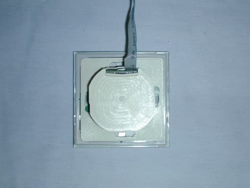
Click to zoom
Application Details
- Equipment Class
- DXX - Part 15 Low Power Communication Device Transmitter
- Date of Grant
- Jun 27, 2002
- Application Purpose
- Original Equipment
- Date of Application
- Jun 27, 2002
- Equipment Note
- Tag Reader
- Frequency Range
- 0.12500000 - 0.12500000
- Company
- Interflex N.A.
- Country
- United States
Documents & Files
Document Text
Text extracted from the exhibit documents filed with the FCC. Open a document above to read the original.
Users Manual
INA-002 / April 2002 FCC (Federal Communications Commission) Installation Supplement- IF P 600 / IF P 603 IMPORTANT NOTE! INTERFLEX SUPPRESSION CORE FRP0003 MUST BE INSTALLED ON RIBBON CABLE BETWEEN MPU BOARD AND CONNECTOR BOARD THIS DEVICE COMPLIES WITH PART 15 OF THE FCC RULES. OPERATION IS SUBJECT TO THE FOLLOWING TWO CONDITIONS: (1) THIS DEVICE MAY NOT CAUSE HARMFUL INTERFERENCE, AND (2) THIS DEVICE MUST ACCEPT ANY INTERFERENCE RECEIVED, INCLUDING INTERFERENCE THAT MAY CAUSE UNDESIRED OPERATION. CAUTION! CHANGES OR MODIFICATIONS NOT EXPRESSLY APPROVED BY THE PARTY RESPONSIBLE FOR COMPLIANCE COULD VOID THE USER’S AUTHORITY TO OPERATE THE EQUIPMENT.
Cover Letter(s)
Curtis-Straus LLC 527 Great Road Littleton, Massachusetts 01460 Tel: 978.486.8880 Fax: 978.486.8828 Web: www.curtis-straus.com e-mail: [email protected] Worldwide Regulatory Approvals Experts ® Federal Communications Commission 7435 Oakland Mills Road Columbia, MD 21046 Gentlemen: This letter is to comply with 47 CFR 0.457(d)(2) pertaining to confidential material. Interflex N.A., Inc. requests that the following document regarding this submission for FCC ID P8KPXFB be kept confidential: 1. Schematic The material above contains technical data, which would customarily be guarded from competitors. We at Curtis-Straus LLC are acting as an Agent on behalf of Interflex N.A., Inc. in requesting confidentiality with regards to the preceding documents. Sincerely, Michael Buchholz Senior EMC Manager Curtis-Straus LLC 527 Great Road Littleton, MA 01460
Cover Letter(s)
Response to FCC Correspondence 11645 AC Line conducted measurement test data and test procedure is addressed in the additional test report submitted. CE note has been added to the grant of equipment authorization as well. ________________________________________________________________ To: Jon Curtis From: Diane Poole [email protected] FCC Equipment Authorization Branch Re: FCC ID: P8KPXFB Applicant: Interflex N.A. Correspondence Reference Number: 11645 731 Confirmation Number: TC563702 Date of Original Email: 03/24/2004 Subject: FCC Equipment Authorization System Please submit the conducted measurement data and conducted test procedure. The items indicated above must be submitted before processing can continue on the above referenced application. Failure to provide the requested information within 30 days of the original e-mail date may result in application dismissal pursuant to Section 2.917(c). DO NOT Reply to this email by using the Reply button. In order for your response to be processed expeditiously, you must upload your response via the Internet at www.fcc.gov , E-Filing, OET TCB Electronic Filing, TCB Login. If the response is submitted through Add Attachments, a message which informs the processing staff that a new exhibit has been submitted must also be submitted via Submit Correspondence. Also, please note that partial responses increase processing time and should not be submitted. Any questions about the content of this correspondence should be directed to the e-mail address listed below the name of the sender.
External Photos
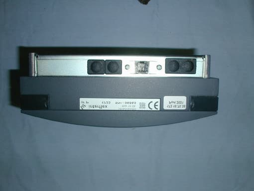
External Pictures Model: IF P600 FCC ID: P8KPXFB Model: IF P600 FCC ID: P8KPXFB
External Photos
External Pictures Model: IF P603 FCC ID: P8KPXFB Model: IF P603 FCC ID: P8KPXFB
ID Label/Location Info
Label Information UL969 recognized system: Label Material - 3M 7613 UL file - MH16411 printer/ink combination (15) IF P600 Label Placement Label is visible during installation. IF P603 Label Placement Label is visible during installation.
Internal Photos
Internal Pictures Model: IF P600 FCC ID: P8KPXFB Model: IF P600 FCC ID: P8KPXFB Model: IF P600 FCC ID: P8KPXFB Model: IF P600 FCC ID: P8KPXFB Model: IF P600 FCC ID: P8KPXFB Model: IF P600 FCC ID: P8KPXFB Model: IF P600 FCC ID: P8KPXFB
Internal Photos
Internal Pictures Model: IF P603 FCC ID: P8KPXFB Model: IF P603 FCC ID: P8KPXFB Model: IF P603 FCC ID: P8KPXFB Model: IF P603 FCC ID: P8KPXFB Model: IF P603 FCC ID: P8KPXFB Model: IF P603 FCC ID: P8KPXFB Model: IF P603 FCC ID: P8KPXFB Model: IF P603 FCC ID: P8KPXFB Model: IF P603 FCC ID: P8KPXFB Model: IF P603 FCC ID: P8KPXFB Model: IF P603 FCC ID: P8KPXFB Model: IF P603 FCC ID: P8KPXFB Model: IF P603 FCC ID: P8KPXFB
Test Report
MEASUREMENT/TECHNICAL REPORT Company: Interflex N.A., Inc. FRN: 0006-6303-47 Models IF P600 IF P603 FCC ID: P8KPXFB Description: This is a report to support a request for an original grant of equipment authorization. Equipment Type: Low Power Communications Device Transmitter (DXX) Report prepared for: Interflex, Inc. 20 Dolphin Road P.O. Box 9338 Forestville, CT 06011-9338 Phone: 860-582-8300 Fax: 860-582-8304 Report prepared by: Evan D. Gould Curtis-Straus LLC 527 Great Road Littleton, MA 01460 USA Phone: 978-486-8880 FAX: 978-486-8828 FCC Application for Interflex, Inc. •• FCC ID:P8KPXFB •• Report No. EB1260-7 30-Apr-02 ______________________________________________________________________ _____________________________ ________________________________ Curtis-Straus LLC •• 527 Great Road •• Littleton, MA •• TEL (978) 486-8880 •• FAX (978) 486-8828 page 2 of 12 Introduction This report is an application for Certification of a Transmitter operating pursuant to 47 CFR 15.209. The model numbers covered by this report are IF P600 and IF P603. Both of these devices contain the same transmitter (Philips HTRC110). This report is designed to demonstrate the compliance of these devices with the requirements outlined in 47 CFR Part 15 using the methods outlined in 47 CFR Part 2. FCC Application for Interflex, Inc. •• FCC ID:P8KPXFB •• Report No. EB1260-7 30-Apr-02 ______________________________________________________________________ _____________________________ ________________________________ Curtis-Straus LLC •• 527 Great Road •• Littleton, MA •• TEL (978) 486-8880 •• FAX (978) 486-8828 page 3 of 12 Statement of Conformity The Interflex IF P600, and IF P603 have been found to conform with the following parts of the 47 CFR as detailed below: Part 2 Part 15 Comments 15.15(b) The products contain no user accessible controls that increase transmission power above allowable levels. 2.925 15.19 The label is shown in the label exhibit. 15.21 Information to the user is shown in the instruction manual exhibit. 15.27 A section in the installation manual details the use of special accessories that are required for compliance. 15.31(e) Readings were taken at the fundamental frequency with the supply voltage varied 15% below the lowest nominal rated voltage and 15% above the highest nominal rated voltage. 15.203 An antenna is printed directly on the transmitter board. 15.205 15.209 The fundamental is not in a Restricted band and the spurious emissions in the Restricted bands comply with the general emission limits of 15.209. 15.207 The unit is DC powered without the capability of being operated from the AC mains. FCC Application for Interflex, Inc. •• FCC ID:P8KPXFB •• Report No. EB1260-7 30-Apr-02 ______________________________________________________________________ _____________________________ ________________________________ Curtis-Straus LLC •• 527 Great Road •• Littleton, MA •• TEL (978) 486-8880 •• FAX (978) 486-8828 page 4 of 12 Test Methodology Radiated emission testing was performed according to the procedures in ANSI C63.4 (1992). The testing was performed at an antenna to EUT distance of 3 or 1 meter(s) below 30MHz and a distance of 10 meters above 30MHz. The actual test distance used is noted in the test data sheets. The device’s performance was investigated to 1GHz. The EUT was powered by a 24V DC power supply. Since the device is installed in one orientation, the emissions were maximized around the vertical axis and the maximum reading was recorded. The integrated antenna cannot be maximized separately. All other performance tests were made in accordance with the procedures outlined in Part 15 of CFR 47. The applicable sections provided under Part 15 are provided in the measurement section of this report. FCC Application for Interflex, Inc. •• FCC ID:P8KPXFB •• Report No. EB1260-7 30-Apr-02 ______________________________________________________________________ _____________________________ ________________________________ Curtis-Straus LLC •• 527 Great Road •• Littleton, MA •• TEL (978) 486-8880 •• FAX (978) 486-8828 page 5 of 12 Test Facility Curtis-Straus LLC All testing for the range 9kHz–1000MHz was performed at Curtis-Straus (A2LA Certificate Number 1627-01). The open area test site used to collect the radiated data is located at 527 Great Road, Littleton, MA 01460. Sites “A” and “T” were used. FCC Application for Interflex, Inc. •• FCC ID:P8KPXFB •• Report No. EB1260-7 30-Apr-02 ______________________________________________________________________ _____________________________ ________________________________ Curtis-Straus LLC •• 527 Great Road •• Littleton, MA •• TEL (978) 486-8880 •• FAX (978) 486-8828 page 6 of 12 Test Equipment Used SPECTRUM ANALYZERS x Analyzer Model No. Company Serial No. Calibration Due X GREEN 9kHz-26.5GHz 8593E HP 3829A03618 04-OCT-2002 X BLACK 9kHz-12.8GHz 8596E HP 3710A00944 29-JUN-2002 X ORANGE 9kHz-26.5GHz E4407B HP US39440975 18-MAY-2002 OPEN AREA TEST SITES (OATS) x Site FCC Code IC Code VCCI Code Calibration Due X “T” Texas 93448 IC 2762-T R-905/ C-480 09-SEP-2002 X “A” Alaska 93448 IC 2762-A R-903/ C-480 23-JUN-2002 ANTENNAS x Antenna Model No. Company Serial No. Calibration Due X GREEN-WHITE Bilog: 30MHz-2GHz CBL6112B Chase 2574 28-JUN-2002 X SMALL LOOP Passive Loop: 9kHz-30MHz PLA-130/A ARA 1024 27-JAN-2003 X LARGE LOOP Passive Loop: 20Hz-5MHz 6511 EMCO 9704-1154 05-NOV-2003 PREAMPLIFIERS x Preamplifier Model No. Company Serial No. Calibration Due X BLUE 0.01-2000MHz ZFL-1000-LN MiniCircuits/ C-S n/a 18-MAY-2002 X BLACK 0.01-2000MHz ZFL-1000-LN MiniCircuits/ C-S n/a 22-MAR-2003 Unless otherwise noted the calibration interval is one year. All equipment is calibrated using standards traceable to NIST or other nationally recognized calibration standard. FCC Application for Interflex, Inc. •• FCC ID:P8KPXFB •• Report No. EB1260-7 30-Apr-02 ______________________________________________________________________ _____________________________ ____________…
Text truncated - open the document above for the full version.
Test Report
Test Report for Interflex Curtis-Straus LLC is accredited by the American Association for Laboratory Accreditation for the specific scope of accreditation under Certificate Number 1627-01. This report may contain data which is not covered by the A2LA accreditation. _____________________________________________________________ Curtis-Straus LLC • 527 Great Road • Littleton, MA • TEL (978) 486-8880 • FAX (978) 486-8828 page 1 of 11 Test Report FCC ID P8KPXFB Client Interflex Item tested IF P600 Standards Class B FCC/CISPR AC line conducted emissions Test Dates June 4, 2003 Results As detailed within this report Prepared by Evan Gould – Test Engineer Authorized by Michael Buchholz – EMC Manager Issue Date 4/1/04 Conditions of Issue This Test Report is issued subject to the conditions stated in the ‘Terms and Conditions’ section on page 7 of this report. Test Report for Interflex Introduction On June 4, 2003 the IF P600 was tested for Class B FCC/CISPR AC line conducted emissions in the range 150kHz – 30MHz. The FCC ID P8KPXFB covers two models: P600 and P603. Both models have the same transmitter. Setup Photo IF P600 _____________________________________________________________ Curtis-Straus LLC • 527 Great Road • Littleton, MA • TEL (978) 486-8880 • FAX (978) 486-8828 page 2 of 11 Test Report for Interflex Measurements AC Mains Conducted Emissions Curtis-Straus LLC Date: 04-Jun-03 Company: Interflex Table No: 1 Engineer: Evan Gould EUT Desc: P600 Work Order: D0428 Notes:Test Site: EMI 2 LISN(s): Orange Range: 0.15-30Mhz Other Equipment:Spectrum Analyzer: Blue Q.P. ReadingsAve. Readings Impedance Factor FCC/CISPR BFCC/CISPR B Overall FrequencyQP1QP2AV1AV2qp Limitqp MarginAVE LimitAVE MarginResult (MHz)(dBμV)(dBμV)(dBμV)(dBμV)(dB)(dBμV)dB(dBμV)dB(Pass/Fail) 9.1413.114.020.060.0-26.050.0-16.0Pass 9.3912.913.720.060.0-26.350.0-16.3Pass 16.5013.313.620.060.0-26.450.0-16.4Pass 17.0012.113.220.060.0-26.850.0-16.8Pass 26.0011.510.320.060.0-28.550.0-18.5Pass 26.5011.812.520.060.0-27.550.0-17.5Pass Table Result: Pass by -16.00 dB Worst Freq: 9.14 MHz _____________________________________________________________ Curtis-Straus LLC • 527 Great Road • Littleton, MA • TEL (978) 486-8880 • FAX (978) 486-8828 page 3 of 11 Test Report for Interflex Test Procedure Line Conducted Emissions Overview REV 25-OCT-02 Digital and microprocessor based devices use radio frequency (RF) digital techniques for timing purposes and in applications such as switching power supplies. An unintentional consequence of this for AC powered devices is that a certain amount of the RF energy is impressed upon the AC power mains in the form of a conducted noise voltage. These conducted emissions have the potential to interfere with constructive uses of the RF spectrum such as AM radio and may also interfere with other devices attached to the same AC mains circuit. In order to reduce the likelihood that a device will interfere it is required that the conducted RF signals from the device are below an allowable level. Testing is performed according to test methods from ANSI C63.4:1992 and CISPR 22:1998. Line conducted emissions are measured from the device over the frequency range of 0.15 to 30 MHz. The EUT is powered from a Line Impedance Stabilization Network (LISN). The purpose of the LISN is to provide a calibrated impedance across which to measure the conducted emissions. The RF noise voltage produced by the EUT across the LISN is measured and compared to the limit. In order for the LISN to perform properly it is attached to a ground plane at least 2 meters by 2 meters in size. For tabletop equipment the measurement is performed with the equipment 40 cm from a vertical conducting surface bonded to a ground plane under the product. The ground plane extends 0.5 meters beyond the product and is 2.5mx3.7m in size. The vertical surface is 2.5mx2.5m. As with radiated emissions, the “human factor” is accounted for by the use of a “quasi-peak” detector in the receiver or spectrum analyzer that measures the signal from the LISN. For certain tests (such as EN55022), both an average and a quasi-peak limit are specified. Emissions from a device must be below both limits when measured with the appropriate detector. If the emission level is below the average limit when measured with the quasi-peak detector, the EUT is presumed to pass both limits. The possible operating modes of the EUT are explored to determine the configuration that maximizes emissions. Software is investigated as well as different methods of displaying data if available. Data is recorded in the worst case operating mode. As of September 9, 2002, the FCC has harmonized it’s conducted emission limits with CISPR. The following table displays the limits applicable to both FCC and CISPR. _____________________________________________________________ Curtis-Straus LLC • 527 Great Road • Littleton, MA • TEL (978) 486-8880 • FAX (978) 486-8828 page 4 of 11 Test Report for Interflex Line Conducted Emissions Limits: Class A (dBμV) Frequency (MHz)Quasi-PeakAverage 0.15 - 0.57966 0.5 - 307360 Line Conducted Emissions Limits: Class B (dBμV) Frequency (MHz)Quasi-PeakAverage 0.15 - 0.566 - 56*56 - 46* 0.5 - 55646 5 - 306050 Note 1: The lower limit applies at the transition frequencies *Note 2: The limit decreases linearly with the logarithm of the frequency Although the FCC is now accepting the limits shown above, it should be noted that the former FCC limits may be used until July 11, 2005 for any equipment authorized prior to July 12, 2004. At least the six highest emissions with respect to the limit are recorded. If less than six emissions are visible above the noise floor of the instrumentation, then the noise floor at six representative frequencies is recorded. The test report will document if noise floor readings are reported. Standard Uncertainty per NIST Technical Note 1297 1994 for this test is estimated to be 2dB. All testing is performed within the framework of a laboratory qualit…
Text truncated - open the document above for the full version.
Test Setup Photos
Setup Photos Model: IF P600 FCC ID: P8KPXFB Model: IF P603 FCC ID: P8KPXFB
Contact Information
Applicant
David C DeBiase(Electronic Engineer)
Test Firm
Curtis-Straus LLCJonathan Stewart
Technical Specifications
| # | Rule Parts | Frequency Range | Power Output |
|---|---|---|---|
| 1 | 15C | 0.125 MHz - 0.125 MHz | - |
Other Applications from Interflex N.A.
P8KPXFA
Jun 03, 2002Proximity Reader
Equipment Class
DXX - Part 15 Low Power Communication Device Transmitter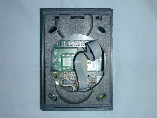
P8KHID
Jun 03, 2002Proximity Reader
Equipment Class
DXX - Part 15 Low Power Communication Device Transmitter