P9GAWE020MTBHand Free Base Set
ABERA SYSTEMS CORPORATION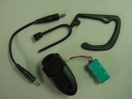
Click to zoom
Application Details
- Equipment Class
- DXT - Part 15 Low Power Transceiver, Rx Verified
- Date of Grant
- May 29, 2002
- Application Purpose
- Original Equipment
- Date of Application
- May 29, 2002
- Equipment Note
- Hand Free Base Set
- Frequency Range
- 2420.00000000 - 2420.00000000
- Company
- ABERA SYSTEMS CORPORATION
- Country
- Taiwan
Documents & Files
Document Text
Text extracted from the exhibit documents filed with the FCC. Open a document above to read the original.
Users Manual
Bridge NOTE: Normally, you answer a call by pressing the On/Off-button on your earpiece and then the "Answer" key on your mobile phone. If you have activated the "Auto Answer" function on your mobile phone, you only have to press the On/Off-button on your earpiece within 3 rings to answer a call. For more information on how to activate the "Auto Answer" function,please refer to your mobile phone user's manual. Please use Nokia standard travel charger to charge the wireless earpiece fully before using it for the first time. Wireless Station Earpiece Package Content Your Earpiece comes with the following items: Ear-hook Basic Specification RF Transmission Power : 1 mW Transmission Range : 0~5 M Talk Time : 80 Minutes Standby : 80 Hours Charge Time : Earpiece: 3.5 Hours Base: 3.5 Hours Earpiece + Base : 3.5 Hours (synchronal charge) Compatible System : GSM 900, GSM 1800, CDMA, TDMA, PCS, AMPS PHS Dimensions : Earpiece: 136 ( L )x 30 ( W )x27 ( T ) mm Including ear-hook: 139 ( L ) x 57.5 ( W ) x 27 ( T ) mm Base: 41 ( L )x 36 ( W )x17 ( T ) mm Weight: : Earpiece (including Battery): 25.5 g Including ear-hook (including Battery): 29.5 g Base(including Battery): 21g Rechargeable Battery: Ni-Mh 3.6 V, 80 mhA, 100 mhA(Base) Certificate : CE , FCC ABERA Innovate For A Better ERA ABERA SYSTEMS CORPORATION 8F, No. 31, Hsintai Road, Chupei City, Hsinchu 302, Taiwan, R.O.C. TEL: 886-3-553-6106 FAX: 886-3-553-6102 Web site: http://www.abera.com.tw http:// www.globalsources.com/abera.co Email: [email protected] This device complies with Part 15 of the FCC Rules. Operation is subject to the following two conditions: (1) This device may not cause harmful interference, and (2) this device must accept any interference received, including interference that may cause undesired operation. Caution:. Any changes or modifications not expressly approved by the party responsible for compliance could void the user's authority to operate this equipment.
Block Diagram
12345678 A B C D 87654321 D C B A Title NumberRevisionSize A3 Date:30-Jun-2001Sheet of File:E:\Hartronics\Whf\hf6100_fcc_bl.schDrawn By: AMP PLL LPF PHASE COMP PRESCALER AUDIO_IN AUDIO_OUT DEMODULATOR
Cover Letter(s)
-----Original Message----- From: Yu-Min Hsieh [mailto:[email protected]] Sent: Sunday, May 26, 2002 8:59 PM To: Mike Kuo Subject: Re: UPDATE ABERA - FCC ID:P9GAWE020MTB, AN02T1983 ( Base) Dear Mr Kuo, Regarding to your questions to my report, indeed, it's my fault. Footnote No.3 should be revised as 'peak detection'. And I already corrected it in the report(Page 8). I used peak detection because it was not over the average limits. So I can assure that its average reading must be in the limits. You mentioned that the emissions near 18GHz are over the limits. Yes, but it was not from the EUT but from the instrument itself. I made it dispeared as I changed the stop frequency to 17.5GHz. (Page 13,14) ------------------------------- The following pages in the report have been changed : P8,P13-P16. The others remain unchanged. ------------------------------- Sincerely, Yu-Min Hsieh =========================== EMC & Radio Testing Lab Telecom Laboratories Chunghwa Telecom Co., Ltd Tel : 886 3 424-5186 Fax: 886 3 420-2444 =========================== ----- Original Message ----- From: Mike Kuo To: 'Yu-Min Hsieh' Sent: Friday, May 24, 2002 9:54 AM Subject: RE: ABERA SYSTEMS CORPORATION, FCC ID:P9GAWE020MTB, AN02T1983 ( Base) Hi Mr. Hsieh: Question #8: Page 8 of 19 of revised test report, Footnote No 3 indicates above 1GHz are measured with average detector. However, page 13-16 of test plots are using peak reading. Please confirm the detector setting used for those emissions reported in Page 8 of 19. Question #9:Page 13 and page 14 of spectrum plots are scanned from 1GHz - 18GHz. The marker placed on the second harmonics is not the highest readings. As indicated on the spectrum plots, the emission nears 18GHz are over the average limits. The RBW used in this plot is 1MHz and VBW=3MHz which is peak reading. If the peak readings are over the average limit, average readings are required. Best Regards Mike Kuo From: Yu-Min Hsieh [[email protected]] Sent: Thursday, May 16, 2002 10:02 PM To: Mike Kuo Subject: Re: ABERA SYSTEMS CORPORATION, FCC ID:P9GAWE020MTB, AN02T1983 ( Base) Dear Mr Kuo, Attached is the document update. Please take some time to process it. The application fee is already in your bank account. Sincerely, Yu-Min Hsieh =========================== EMC & Radio Testing Lab Telecom Laboratories Chunghwa Telecom Co., Ltd Tel : 886 3 424-5186 Fax: 886 3 420-2444 =========================== ----- Original Message ----- From: Mike Kuo To: '[email protected]' ; '[email protected]' Sent: Wednesday, May 08, 2002 9:01 AM Subject: FW: ABERA SYSTEMS CORPORATION, FCC ID:P9GAWE020MTB, AN02T1983 ( Base) -----Original Message----- From: CERTADM Sent: Tuesday, May 07, 2002 5:47 PM To: '[email protected]' Subject: ABERA SYSTEMS CORPORATION, FCC ID:P9GAWE020MTB, AN02T1983 (Base) Notice_content ------------- Question #1: Please provide additional internal photos by removing the metal shielding . Take a close up photo to show the component site of PCB without the shielding plate. Question #2: User Manual does not contain information required under section 15.21 of FCC rules. Please provide revised user manual to comply this requirement. Question #3: Page 5 of test report has typo. It listed 15.49 as the technical requirement. Please make necessary change. Question #4: The tabular data section 2.1.3 and 2.2.3 represented in the test report, there is no information on the elements of correction factors that were considered and formula used to have corrected readings. Please provide such information. Question #5: In accordance with 15.249 technical requirements, the field strength for fundamental frequency is 50 mV/m. This is the average limits. Section 15.249 (d) indicates when the limit is average, the peak limit ( Average limit + 20dB ) is also applied. In addition, the RBW that you used to measure the fundamental field strength is 3MHz with VBW of 10kHz. Such settings do not comply with ANSI C63.4 section 4.2 requirement. Please redo the measurement and submit the data. Please make sure to provide peak and average reading if the peak readings are above average limits. Question #6: The spectrum plots provided for spurious emission do not show the RBW and VBW used, please provide such information and show all the correction factors that used. Question #7: Mode of operation: in accordance with ANSI C63.4 section 13.1.1.1 applied modulation " If the device is equipped with input connector for external modulation, typical modulating signals shall be applied at the max. rated input level for the device when modulation is required in an individual test" As indicated in the test setup photos and support equipment used, there are no such external modulating device was connected. Please redo radiated emission tests with external modulation. Best Regards Mike Kuo / TCB Certifier The items indicated above must be submitted before processing can continue on the above referenced application. Failure to provide the requested information within 60 days of the original e-mail date may result in application dismissal and forfeiture of the filing fee. Also, please note that partial responses increase processing time and should not be submitted. Any questions about the content of this correspondence should be directed to the e-mail address listed below the name of the sender.
External Photos
PHOTO OF BASESET REAR VIEW FRONT VIEW ACCESSORIES
ID Label/Location Info
BRAND : Abera Wireless Earpiece Model No. : AWE 2.0 (BASESET) FCC ID : P9GAWE020MTB
Internal Photos
PCB FRONT VIEW PCB REAR VIEW
Operational Description
The AWE 2.0 wireless earpiece, which is designed to work between ears of a person and a mobile phone in a distance of about 3m. The baseset working without a battery can be plugged in most of types of mobile phones such as GSM900, DCS 1800 or PHS 1800 as one end of a voice transceiver. The AWE 2.0 earpiece powered by Ni-Mh 3.6V battery hooks to a person’s right or left ear as the other end of a transceiver. When a mobile phone with AWE 2.0 baseset rings, just press the button one time on the AWE 2.0 earpiece to get the call. The AWE 2.0 earpiece can be charged from the battery of a mobile phone through a bridge wire for longer use. The pair of transceiver won’t radiate after power-on when in charge mode.
Schematics
12345678 A B C D 87654321 D C B A Title NumberRevisionSize A3 Date:30-Jun-2001Sheet of File:E:\Hartronics\Whf\hf6100_fcc_ckt.schDrawn By: Q3 C14 2p R12 15K R17 270 R21 22K R18 270 C16 0.5p C20 5p C21 5p C22 5p G=15dB VCC C27 10p AFC_P 1 AFC_A 2 GND 3 OSC+ 4 OSC- 5 AGC_B 6 AGC 7 RF_IN 8 RF_IN 9 VIDEO_OUT 10 VIDEO_F- 11 VIDEO+ 12 VIDEO- 13 VIDEO_F+ 14 VCC 15 AFC_OUT 16 U2 D2 BB833 D3 BB833 L2 10n L3 10n C29150p R24 1.2K R25 1.2K C41 100p C42 100p VCC C440.1u C30150p C49 6p C31 150p VCC R26 20K C45 0.1u Q4 R13 15K R28 47 C32 150p C39 150p R36 10K C40 150p VCC C28 10p R29 47 L4 IND L9 IND Q5 C15 2p R15 15K R19 270 R22 22K R20 270 C17 0.5p C23 5p C24 5p C25 5p VCC Q6 R38 10 R39 10 R23 22K R16 15K C18 0.5p C19 0.5p C50 6p D4 SMV1247-011 C51 6p R41 3K3 C56 6p C57 6p VCC R43 RES L10 IND C64 CAP C65 CAP IN R60 510 R44 RES TDI 2 3 G 5 6 TMS 8 VCC 10 11 12131415GVCC1819202122 23 G 25 TCK 27 28 VCC 30 31 TDO 33 3435 G GCLK1 OE1 GCLRn GCLK2/OE2 VCC 424344 U3 X2 4MHz C82 20p C83 20p R61 1M VCC R46 RES R62 1K R37 10K VCC VCC IN 1 VCC 2 SW1 3 OUT 4 GND 5 SW2 6 GND 7 IN_ 8 C84 C73 CAP VCC L_CARRIER R48 RES C75 CAP C76 CAP C77 CAP R49 RES R50 RES R51 RES R52 RES R54 RES VCC VCC C78 CAP C79 CAP C80 CAP VCC R59 RES C81 CAP R66 ANT IN 1 G 4 OUT 2 G 3 F1 OUT
Test Report
EMC & Radio Equipment Testing Lab Telecommunication Equipment Testing Center Telecommunication Laboratories Chunghwa Telecom Co., Ltd. TEL+886 3 4244238 FAX+886 3 4202444 E-mail:[email protected] http://www.chttl.com.tw NO.12,Lane 551,Min-Tsu Road Sec.5, Yang-Mei, Taoyuan Taiwan,R.O.C. Date of Issue : Apr. 12, 2002 FCC TEST REPORT This test report shall not be reproduced except in full without the written permission of Testing Laboratories of Chunghwa Telecom. 0280 Client : ABERA SYSTEMS CORPERATION Product : Abera Wireless Earpiece (Baseset) Model No. : AWE 2.0 Test report No.TSC-91-03-IN-03a Page No.1 of 19 EMC & Radio Equipment Testing Lab Telecommunication Equipment Testing Center Telecommunication Laboratories Chunghwa Telecom Co., Ltd. TEL+886 3 4244238 FAX+886 3 4202444 E-mail:[email protected] http://www.chttl.com.tw NO.12,Lane 551,Min-Tsu Road Sec.5, Yang-Mei, Taoyuan Taiwan,R.O.C. STATEMENT Client : ABERA SYSTEMS CORPORATION 8F, No. 31, Hsintai Road, Chupei City, Hsinchu 302, Taiwan, R.O.C. Manufacturer : ABERA SYSTEMS CORPORATION 8F, No. 31, Hsintai Road, Chupei City, Hsinchu 302, Taiwan, R.O.C. FCC ID : P9GAWE020MTB Product : Abera Wireless Earpiece (Baseset) Model Number AWE 2.0 Serial Number N/A Brand ABERA Date of Test Sample Received : Mar. 25, 2002 Date of Test : Apr. 2, 2002 –Apr. 10, 2002 Regulation Applied : FCC Part 15 Subpart C Test Result : Compliant WE HEREBY CERTIFY THAT the test data in this report were made in accordance with the regulation FCC Part 15 Subpart C. We assume full responsibility for the accuracy of these data measured. The results in this report is only related to the test sample. Test Engineer : Yu-Min Hsieh Technical Manager : Chi-Chao Chang Test report No.TSC-91-03-IN-03a Page No.2 of 19 EMC & Radio Equipment Testing Lab Telecommunication Equipment Testing Center Telecommunication Laboratories Chunghwa Telecom Co., Ltd. TEL+886 3 4244238 FAX+886 3 4202444 E-mail:[email protected] http://www.chttl.com.tw NO.12,Lane 551,Min-Tsu Road Sec.5, Yang-Mei, Taoyuan Taiwan,R.O.C. TABLE OF CONTENTS 1. General Information...........................................................4 1.1 Description of EUT...............................................................................4 1.2 Basic Specification of EUT...................................................................4 1.3 Test Applicability Table........................................................................5 2. Measurements and Results...............................................6 2.1 Field strength inside of band ...............................................................6 2.1.1 Test Procedure ..............................................................................6 2.1.2 Test Facility Used..........................................................................6 2.1.3 Test Results...................................................................................7 2.2 Emissions outside of authorized band.................................................7 2.2.1 Test Procedure ..............................................................................7 2.2.2 Test Facility Used..........................................................................8 2.2.3 Test Results...................................................................................8 Appendix.............................................................................................9 Test report No.TSC-91-03-IN-03a Page No.3 of 19 EMC & Radio Equipment Testing Lab Telecommunication Equipment Testing Center Telecommunication Laboratories Chunghwa Telecom Co., Ltd. TEL+886 3 4244238 FAX+886 3 4202444 E-mail:[email protected] http://www.chttl.com.tw NO.12,Lane 551,Min-Tsu Road Sec.5, Yang-Mei, Taoyuan Taiwan,R.O.C. 1. General Information 1.1 Description of EUT The Equipment Under Test(EUT) is a wireless earpiece, which is designed to work between ears of a person and a mobile phone in a distance of about 3m. The AWE 2.0 baseset working without a battery can be plugged in most of types of mobile phones such as GSM900, DCS 1800 or PHS 1800 as one end of a voice transceiver. The AWE 2.0 earpiece powered by Ni-Mh 3.6V battery hooks to a person’s ear as the other end of a transceiver. When a mobile phone with AWE 2.0 baseset rings, just press the button one time on the AWE 2.0 earpiece to get the call. The AWE 2.0 earpiece can be charged by the battery of a mobile phone through a bridge wire for longer use. The pair of transceiver won’t radiate after power-on when in charge mode. 1.2 Basic Specification of EUT RF Transmission Frequency : 2420 MHz Type of Modulation : FM Transmission Range : 0 ~ 3 m Working Duration : 80 minutes Stand-by Time : 80 hours Charge time : 3.5 Hours Compatible System : GSM 900 / DCS 1800 / PHS 1800 Dimension : Headset 139(L) X 57.5(W) X 25.5(T) mm Baseset 136(L) X 30(W) X27(T) mm Weight : Earpiece : 25.5g Baseset : 21g Rechargeable Battery : Ni-Mh 3.6V, 80mA Mode of operation : On & Off Mode/ Charge Mode (No ports for any input signals) Test report No.TSC-91-03-IN-03a Page No.4 of 19 EMC & Radio Equipment Testing Lab Telecommunication Equipment Testing Center Telecommunication Laboratories Chunghwa Telecom Co., Ltd. TEL+886 3 4244238 FAX+886 3 4202444 E-mail:[email protected] http://www.chttl.com.tw NO.12,Lane 551,Min-Tsu Road Sec.5, Yang-Mei, Taoyuan Taiwan,R.O.C. 1.3 Test Applicability Table Test Item ApplicabilityRemark Antenna requirement – per 15.203 no The antenna is soldered on board and not interchangeable Radiated Emissions – per 15.209 & 15.49 yes none Conducted Emissions – per 15.207 no Powered by 3.6V battery Test report No.TSC-91-03-IN-03a Page No.5 of 19 EMC & Radio Equipment Testing Lab Telecommunication Equipment Testing Center Telecommunication Laboratories Chunghwa Telecom Co., Ltd. TEL+886 3 4244238 FAX+886 3 4202444 E-mail:[email protected] http://www.chttl.com.tw NO.12,Lane 551,Min-Tsu Road Sec.5, Yang-Mei, Taoyuan Taiwan,R.O.C. 2. Measurements and Results 2.…
Text truncated - open the document above for the full version.
Test Setup Photos
EMC & Radio Equipment Testing Lab Telecommunication Equipment Testing Center Telecommunication Laboratories Chunghwa Telecom Co., Ltd. TEL+886 3 4244238 FAX+886 3 4202444 E-mail:[email protected] http://www.chttl.com.tw NO.12,Lane 551,Min-Tsu Road Sec.5, Yang-Mei, Taoyuan Taiwan, R.O.C. Test Setup for power measurement at 30~1000Mhz Test report No.TSC-91-03-IN-03a Page No.17 of 19 EMC & Radio Equipment Testing Lab Telecommunication Equipment Testing Center Telecommunication Laboratories Chunghwa Telecom Co., Ltd. TEL+886 3 4244238 FAX+886 3 4202444 E-mail:[email protected] http://www.chttl.com.tw NO.12,Lane 551,Min-Tsu Road Sec.5, Yang-Mei, Taoyuan Taiwan, R.O.C. Test Setup for fundamental power Test report No.TSC-91-03-IN-03a Page No.18 of 19 EMC & Radio Equipment Testing Lab Telecommunication Equipment Testing Center Telecommunication Laboratories Chunghwa Telecom Co., Ltd. TEL+886 3 4244238 FAX+886 3 4202444 E-mail:[email protected] http://www.chttl.com.tw NO.12,Lane 551,Min-Tsu Road Sec.5, Yang-Mei, Taoyuan Taiwan, R.O.C. Test Setup for harmonic power Test report No.TSC-91-03-IN-03a Page No.19 of 19
Contact Information
Applicant
Hawk Lee(FAE)
Test Firm
Chunghwa Telecom Co., Ltd.Chi-Chao Chang
Technical Specifications
| # | Rule Parts | Frequency Range | Power Output |
|---|---|---|---|
| 1 | 15C | 2.42 GHz - 2.42 GHz | - |
Other Applications from ABERA SYSTEMS CORPORATION
P9GAWE020EPC
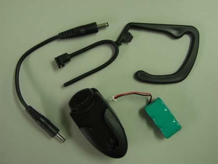
May 29, 2002Hand Free Head Set
Equipment Class
DXT - Part 15 Low Power Transceiver, Rx Verified