P9UGH3080DT2.4GHz 40 Channel Analog Modulation Cordless Phone
Datamec Communications Ltd.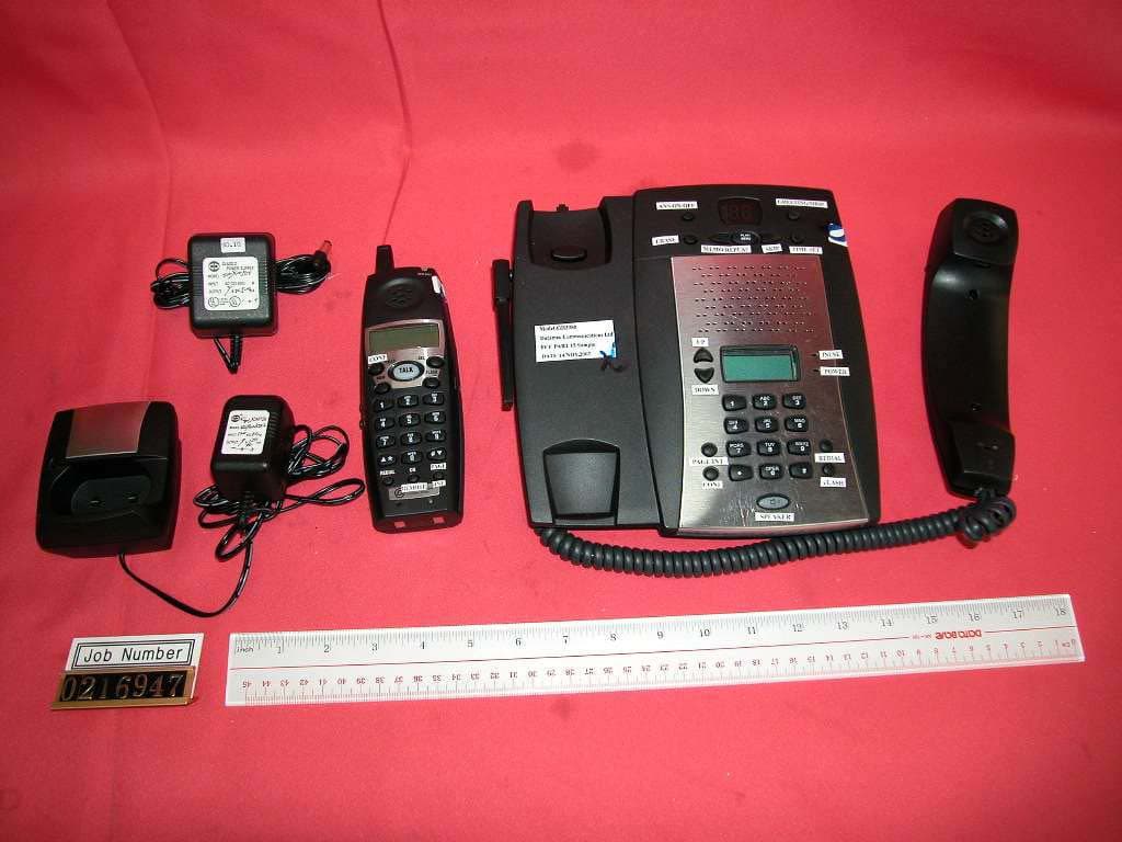
Click to zoom
Application Details
- Equipment Class
- DXT - Part 15 Low Power Transceiver, Rx Verified
- Date of Grant
- Mar 23, 2003
- Application Purpose
- Original Equipment
- Date of Application
- Mar 23, 2003
- Equipment Note
- 2.4GHz 40 Channel Analog Modulation Cordless Phone
- Frequency Range
- 2473.50000000 - 2476.50000000
- Company
- Datamec Communications Ltd.
- Country
- Hong Kong
Documents & Files
Document Text
Text extracted from the exhibit documents filed with the FCC. Open a document above to read the original.
Users Manual
GH3080 OWNER`S MANUAL Toll-Free Helpline 1-800-366-0937 http://www.swbfreedomphone.com STOP-DON`T TAKE ME BACK TO THE STORE. LOOK-FOR THE TOLL-FREE ``HELP`` TELEPHONE NUMBER. LISTEN-AS THE EXPERTS TALK YOU THROUGH THE PROBLEM. For immediate answers to your questions regarding operation, missing parts or installation, call: Southwestern Bell Freedom PHONE ® Retail Sales Help Line at 1-800-366-0937 Monday-Friday 8:30 a.m. -9:00 p.m. EST Saturday 8:30 a.m. - 12:30 p.m. EST http:// www. swbfreedomphone.com SOUTHWESTERN BELL FREEDOM PHONE 7475 N. GLEN HARBOR BLVD., GLENDALE, AZ 85307 GH3080 IB-3887 Printed in China 2.4GHz Cordless Telephone with Call Waiting Caller ID And Digital Answering/Speakerphone System Southwestern Bell Freedom Phone ® SPEAKER G H Z 2 . 4 REDIAL/PAUSE GREET/STOP 3 MNO WXYZ 6 # 9 DEF 8 JKL TUV 5 0 OPER 2 ABC PLAY/ MEMO SKIP IN USE POWER ANSWER PAGE/INTCM ERASE ON/OFF CONF GHI PQRS * 4 7 1 BACK FLASH DAY/TIME PDF created with FinePrint pdfFactory trial version http://www.fineprint.com PLEASE READ IMPORTANT SAFETY INSTRUCTIONS BEFORE USE. Congratulations! You have purchased a 2.4GHz Cordless Telephone with All Digital Answering Speakerphone System that has been manufactured to the highest standards of SOUTHWESTERN BELL FREEDOM PHONE ® Retail Sales. Its ``DIGICLEAR PLUS TM `` circuitry combines noise filtering with state of the art technology that reduces background noise from your telephone conversations. Special compander circuitry compresses, then expands, the transmitted signal to enhance clean, clear audio. BEFORE INSTALLING AND OPERATING THIS TELEPHONE, IT IS VERY IMPORTANT THAT YOU READ THIS OWNER`S MANUAL. BEFORE USING YOUR TELEPHONE EQUIPMENT, BASIC SAFETY PRECAUTIONS SHOULD ALWAYS BE FOLLOWED TO REDUCE THE RISK OF FIRE, ELECTRIC SHOCK AND INJURY TO PERSONS, INCLUDING THE FOLLOWING: 1. Read and understand all instructions. 2. Follow all warnings and instructions marked on the product. 3. Unplug this product from the wall telephone jack and power outlet before cleaning. Do not use liquid or aerosol cleaners. Use a damp cloth for cleaning. 4. Do not use this product near water: such as, near a bathtub, wash bowl, kitchen sink, laundry tub, swimming pool, or in a wet basement. 5. Do not place this product on an unstable cart, stand or table. The product may fall, causing serious damage. 6. Slots or openings in the cabinet and the back and bottom are provided for ventilation, to protect product from overheating. These openings must not be blocked or covered. The openings should never be blocked by placing the product on a bed, or other similar surface. This product should never be placed near or over a radiator or heat register. 7. This product should be operated only from the type of power source indicated on the marking label. If you are not sure of the type of power supply in your home, consult your dealer or local power company. 8. Do not allow anything to rest on the power cord. Do not place this product where the cord will be damaged by persons stepping on it. 9. Do not overload wall outlets and extension cords, as this can result in fire or electric shock. 10. Never push objects of any kind into this product through cabinet slots, as they may touch dangerous voltage points or short out parts. This could result in fire or electric shock. Never spill liquid of any kind on the product. 11. To reduce the risk of electric shock, do not disassemble this product. Instead, when service or repair work is required, take it to a qualified service technician. Opening or removing covers may expose you to dangerous voltages or other risks. Incorrect reassembly can cause electric shock when the appliance is subsequently used. 12. Unplug this product from the wall outlet and refer servicing to qualified service personnel under the following conditions: a. When the power supply cord or plug is damaged or frayed. b. If liquid has been spilled into the product. c. If the product has been exposed to rain or water. d. If the product does not operate normally and proper operating instructions have been followed, adjust only those controls that are covered by the operating instructions. Improper adjustment of other controls may result in damage and will often require extensive work by a qualified technician to restore the product to normal operation. e. If the product has been dropped or the cabinet has been damaged. f. If the product exhibits a distinct change in performance. 13. Avoid using a telephone (other than a cordless type) during an electrical storm. There may be a remote risk of electric shock from lightning. 14. Do not use the telephone to report a gas leak in the vicinity of the leak. 15. Use only the power cord and batterless indicated in this manual. Do not dispose of batteries in a fire. They may explode. Check with local codes for possible special dispocial instructions. 12 CAUTION Danger of explosion if battery is incorrectly replaced. Replace only with the same or aquivalent type recommended by the manulacturer. Dispose of used batteries according to the manufacturer`s instructions. IMPORTANT SAFETY INSTRUCTIONS PDF created with FinePrint pdfFactory trial version http://www.fineprint.com Use only a Southwestern Bell Freedom Phone ® approved battery pack in the handset of your GH3080 Cordless Telephone. To reduce the risk of fire or injury, always do the following when replacing, discarding or charging batteries. When handling the batteries, be careful not to short the battery with conducting materials such as rings, bracelets, and keys. The battery or conducting material may overheat and cause burns. a. Use only the following type and size batteries in the cordless phone: Self-contained 3-cell Nickel-Cadmium rechargeable battery supply: b. Do not dispose of the battery pack in a fire. The cell may explode. Check with local codes for possible special disposal instructions. c. Do not attempt to open or mutilate the battery pack. The chemicals are dangerous and may ca…
Text truncated - open the document above for the full version.
Users Manual
FCC WANTS YOU TO KNOW This equipment complies with Part 68 of the FCC rules and the requirements adopted by the ACTA. On the bottom of this equipment is a label that contains, among other information, a product identifier in the format US: DA1W912BGH3080DT. If requested, this number must be provided to the telephone company. An applicable certification jacks Universal Service Order Codes (USOC) for the equipment is provided (i.e., RJ11C) in the packaging with each piece off approved terminal equipment. A plug and jack used to connect this equipment to the premises wiring and telephone network must comply with the applicable FCC Part 68 rules and requipments adopted by the ACTA. A compliant telephone cord and modular plug is provide with this product. It is designed to be connected to a compatible modular jack that is also complaint. See instalation instructions for details. The REN is used to determine the number of devices that may be connected to a telephone line. Excessive RENs on a telephone line may result in the devices not ringing in response to an incoming call. In most but not all areas, the sum of RENs should not exceed five (5.0). To be certain of the number of devices that may be connected to a line, as determined by the total RENs, contact the local telephone company. [For products approved after July 23, 2001, the REN for this product is part of the product identifier that has the format US: DA1W912BGH3080DT. The digits represented by 12 are the REN without a decimal point (e.g., 03 is a REN of 0.3). For earlier products, the REN is separately shown on the label.] If your telephone equipment causes harm to the telephone network, the telephone company may discontinue your service temporarily. If possible, they will notified as soon as possible. You will be informed of your right to file a complaint with the FCC. Your telephone company may make changes in its facilities, equipment, operations, or procedures that could affect the proper functioning of your equipment. If they do, you will be notified in advance to give you an opportunity to maintain uninterrupted telephone service . If you experi- ence trouble with this telephone equipment, disconnect from the network until the problem has been corrected or until you are sure that the equipment is not malfunctioning. This equipment may not be used with coin service provided by the telephone company. Connection to party lines is subject to state tariffs. This equipment is hearing aid compatible. WARNING: Charges or modifications to this unit not expressly approved by the party responsible for compliance could void the user`s authority to operate the equipment. NOTE: This equipment has been tested and found to comply with the limits for a Class B digital device, pursuant to Part 15 of the FCC Rules. These limits are designed to provide reasonable protection against harmful interference in a residential installation. This equipment generates, uses and can radiate radio frequency energy and, if not installed and used in accordance with the instructions, may cause harmful interference to radio communications. However, there is no guarantee that interference will not occur in a particular installation. If this equipment does cause harmful interference to radio or television reception, which can be determined by turning the equipment off and on, the user is encouraged to try to correct the interference by one or more of the following measures: · Reorient or relocate the receiving antenna. ·Increase the separation between the equipment and receiver. ·Connect the equipment into an outlet on a circuit different from that to which the receiver is connected. ·Consult the dealer or an experienced radio TV technician for help. Please follow instructions for repairing if any (e.g. battery replacement section); otherwise do not alternate or repair any parts of device except as specified. NOTICE: If your home has specially wired alarm equipment connected to the telephone line, ensure the installation of this [equipment FCC ID] does not disable your alarm equipment. If you have questions about what will disable alarm equipment, consult your telephone company or a qualified installer. If the equipment is causing harm to the telephone network, the telephone company may request that you disconnect the equipment until the problem is resolved. [NOTICE: According to telephone company reports, AC electrical surges, typically resulting from lightning strikes, are very destructive to telephone equipment connected to AC power sources. To minimize damage from these types of surges, a surge arrestor is recommended.] 56 PDF created with FinePrint pdfFactory trial version http://www.fineprint.com
External Photos
External photos FCC ID: P9UGH3080DT External photos FCC ID: P9UGH3080DT
ID Label/Location Info
PDF created with FinePrint pdfFactory trial version http://www.fineprint.com
Internal Photos
Internal photos FCC ID: P9UGH3080DT Base assembly (View 1) Base assembly (View 2) Internal photos FCC ID: P9UGH3080DT Base Main PCB comp side (view 1) Base Main PCB comp side (view 2) Internal photos FCC ID: P9UGH3080DT Base Main PCB comp side (view 3) Base Main PCB solder side Internal photos FCC ID: P9UGH3080DT Base LCD display PCB comp side Base LCD display PCB rear side Internal photos FCC ID: P9UGH3080DT Base DAM PCB comp side Base DAM PCB rear side Internal photos FCC ID: P9UGH3080DT Corded Handset assembly Corded Handset receiver volume PCB comp side Internal photos FCC ID: P9UGH3080DT Corded Handset receiver volume PCB solder side Base Oscillator PCB comp side Internal photos FCC ID: P9UGH3080DT Base Oscillator PCB solder side Internal photos FCC ID: P9UGH3080DT Handset assembly Handset Main PCB comp side (View 1) Internal photos FCC ID: P9UGH3080DT Handset Main PCB comp side (View 2) Handset Main PCB comp side (view 3) Internal photos FCC ID: P9UGH3080DT Handset Main PCB display side Handset another PCB comp side Internal photos FCC ID: P9UGH3080DT Handset another PCB solder side Handset Oscillator PCB comp side Internal photos FCC ID: P9UGH3080DT Handset Oscillator PCB solder side
Operational Description
The Technical Description of GH3080 Prepared by: W. K. Chan 1. RF Module TX Part: The TX-VCO generates the transmitting frequency, and it is controlled by the MCU in the base-band through the combo-chip (TB31261AF). The output signal is tripled by the TX-BUF and amplified by power amplifier (PAMP-1 and PAMP- 2), then fed to the TX-antenna. The audio signal is fed to the MIC-AMP from the base-band part and then modulated to the RF signal in TX-VCO through the compressor. The DATA is used to transfer the commands between the base unit and the handset. RX Part: The received signal from the RX-antenna is fed to the mixer (Q2) after amplified by LNA-1 and LNA-2. In the mixer it is mixed with the local frequency generated by the RX-VCO and tripled by the tripler (Q14) converted to the IF (10.7MHz) signal, The RX-VCO (Q15) is controlled by the MCU in the base-band part. After amplified by IF-Amp in IC1 (TB31261AF) the IF signal is fed to the FM- demodulator in which the audio signal is picked up. The audio signal is fed to the base-band part through the expander and the speaker amplifier in TB31261AF. The combo chip (TB31261AF) also detects the voltage of the battery and the RSSI to inform the MCU and it is controlled by the MCU through the interface of COMBO_DATA, COMBO_CLK, COMBO_EN. And the other hand, TB31261AF also demodulates the data signal from the received signal and sends to the MCU. 2. The Base Band Part of The Base Unit: Tel. Line Interface: Separate the incoming and outgoing audio signals and make the sidetone cancellation. Make the telephone line on- hook and off hook. Ring Detect and Branch Phone Detect: detects the ring signal from the telephone line in on hook status and inform the MCU, and detects if the branch phone is in the off-hook mode or on-hook mode and then inform to DTAM-MCU. DTAM & Speaker Phone Part: This circuit provides the functions of digital telephone answering and fully-duplex speaker phone. The frequency of the clock is 4.096MHz. DTAM MCU: This MCU provides the user interface with DTAM. And it can communicate with the main MCU of the base. The frequency of the clock is 4.096MHz. Corded Phone Part: This circuit provides the function of communication with the line such as feature phone and also provides the inter-communication with the Cordless HS. Audio Path Switch Circuit: This circuit can set up the paths between the cordless HS, Corded Phone, Speaker Phone and Telephone Line to implement the functions of talking with the line, inter-communication, 3-way conference, cordless HS remote to DTAM, and call screening etc. The circuit is controlled by the base main MCU. Ref. OSC (4MHz): Provide the standard frequency to RX-PLL and TX-PLL of the RF Module as the reference frequency. Power Control Circuit: Switch on or off the powers of TX part RX part of the RF module. It is controlled by the MCU. 3. The Base MCU Board: Main MCU: It’s the central controller. It manages the all parts including the DTAM MCU, the Audio Path Switch Circuit in the base unit to work properly and makes the communication with the handset through the RF link. The frequency of the clock is 32.768KHz. Keyboard and LCD: The user interface. 4. The Base Band Part of The Handset: Keyboard: The user interface. Power Control Circuit: Switch on or off the power of TX-part and RX-part of the handset RF module. Charge Circuit and Charge Detector: Charge the battery in the handset when the handset is in the base cradle and detect if the handset is charging or not, and then inform the MCU. REF OSC (4MHz): Provide the standard frequency to the RX-PLL and TX-PLL of the RF module as the reference frequency. MCU: The central controller. It manages the operation of the handset and communicates with the base unit through the RF link. 5. The Antennas of Base and Handset: There are two antennas that are single pole type and soldered permanently on the RF module of both base and handset, one for TX and one for RX. END Testing Mode Descriptions of GH3080 2.4G CID 2 corded base cordless handset Telephone Base Version 1.0 Modified by Wu Zhi Ji, 25/10/2002 40 Channels Sequencing Table in Test Mode of Base No. of channel 40 Fosc/Fref=R Ch Separation 100kHz Fin/Fref=P Ref Freq (Fref) 16.667kHz Crystal connected (Fosc) 4MHz Ref counter (R) 240 1st IF 10.7MHz CH No. TX freq N for TX RX freq Triple RX LO freq N for RX 0 2401000000 48020 2473500000 2484200000 49684 1 2401100000 48022 2473600000 2484300000 49686 2 2401200000 48024 2473700000 2484400000 49688 3 2401300000 48026 2473800000 2484500000 49690 4 2401400000 48028 2473900000 2484600000 49692 5 2401500000 48030 2474000000 2484700000 49694 6 2401600000 48032 2474100000 2484800000 49696 7 2401700000 48034 2474200000 2484900000 49698 8 2401800000 48036 2474300000 2485000000 49700 9 2401900000 48038 2474400000 2485100000 49702 10 2402000000 48040 2474500000 2485200000 49704 11 2402100000 48042 2474600000 2485300000 49706 12 2402200000 48044 2474700000 2485400000 49708 13 2402300000 48046 2474800000 2485500000 49710 14 2402400000 48048 2474900000 2485600000 49712 15 2402500000 48050 2475000000 2485700000 49714 16 2402600000 48052 2475100000 2485800000 49716 17 2402700000 48054 2475200000 2485900000 49718 18 2402800000 48056 2475300000 2486000000 49720 19 2402900000 48058 2475400000 2486100000 49722 20 2403000000 48060 2475500000 2486200000 49724 21 2403100000 48062 2475600000 2486300000 49726 22 2403200000 48064 2475700000 2486400000 49728 23 2403300000 48066 2475800000 2486500000 49730 24 2403400000 48068 2475900000 2486600000 49732 25 2403500000 48070 2476000000 2486700000 49734 26 2403600000 48072 2476100000 2486800000 49736 27 2403700000 48074 2476200000 2486900000 49738 28 2403800000 48076 2476300000 2487000000 49740 29 2403900000 48078 2476400000 2487100000 49742 30 2404000000 48080 2476500000 2487200000 49744 31 2404100000 48082 2476600000 2487300000 49746 32 2404200000 48084 2476700000 2487400000 49748 33 2404300000 48086 2476800000 2487500000 49750 34 240440000…
Text truncated - open the document above for the full version.
Test Report
• The test results reported in this report shall refer only to the sample actually tested and shall not refer or be deemed to refer to bulk from which such a sample may be said to have been obtained. • This report shall not be reproduced except in full without prior authorization form Intertek Testing Services Limited FCC ID: P9UGH3080DT Intertek Testing Services Hong Kong Ltd. 2/F., Garment Centre, 576 Castle Peak Road, Kowloon, Hong Kong. Tel: (852) 2173 8888 Fax: (852) 2741 1693 Datamec Communications Limited Application For Certification 2.4GHz 40 Channel Analog Modulation Cordless Phone with Caller ID and Digital Answering Machine (FCC ID: P9UGH3080DT) WO# 02169471 TL/Ann Choy March 10, 2003 INTERTEK TESTING SERVICES FCC ID: P9UGH3080DT i LIST OF EXHIBITS INTRODUCTION EXHIBIT 1:General Description EXHIBIT 2:System Test Configuration EXHIBIT 3:Emission Results EXHIBIT 4:Equipment Photographs EXHIBIT 5:Product Labelling EXHIBIT 6:Technical Specifications EXHIBIT 7:Instruction Manual EXHIBIT 8:Security Code Information INTERTEK TESTING SERVICES FCC ID: P9UGH3080DT ii MEASUREMENT/TECHNICAL REPORT Datamec Communications Limited - MODEL: GH3080DT(XXXXX) FCC ID: P9UGH3080DT This report concerns (check one:) Original Grant X Class II Change Equipment Type : Cordless Telephone (example : computer, modem, transmitter, etc.) Deferred grant requested per 47 CFR 0.457(d)(1)(ii)?Yes No X If yes, defer until : date Company Name agrees to notify the Commission by: date of the intended date of announcement of the product so that the grant can be issued on that date. Transition Rules Request per 15.37 ?Yes No X If no, assumed Part 15, Subpart C for intentional radiator - the new 47 CFR [12-18-01 Edition] Provision. Report prepared by:Tommy Leung Intertek Testing Services. 2/F., Garment Centre, 576 Castle Peak Road, Kowloon, Hong Kong. Phone :852-2173-8538 Fax:852-2741-1693 INTERTEK TESTING SERVICES FCC ID: P9UGH3080DT iii Table of Contents 8.0 General Description............................................................................................................2 1.1 Product Description .........................................................................................................2 1.2 Related Submittal(s) Grants ............................................................................................3 1.3 Test Methodology ............................................................................................................3 1.4 Test Facility .....................................................................................................................3 8.0 System Test Configuration.....................................................................................................5 2.1 Justification ......................................................................................................................5 2.2 EUT Exercising Software................................................................................................5 2.3 Support Equipment List and Description........................................................................6 2.4 Measurement Uncertainty ...............................................................................................7 2.5 Equipment Modification..................................................................................................7 8.0 Emission Results......................................................................................................................9 8.1 Field Strength Calculation .............................................................................................10 8.2 Radiated Emission Configuration Photograph - Base Unit ..........................................11 8.3 Radiated Emission Data - Base Unit .............................................................................12 3.4 Radiated Emission Configuration Photograph - Handset .............................................15 3.5 Radiated Emission Data - Handset................................................................................16 3.6 Radiated Emission on the bandedge..............................................................................19 3.7 Line Conducted Configuration Photograph - Base Unit...............................................21 3.8 Line Conducted Emission Data - Base Unit .................................................................22 8.0 Equipment Photographs......................................................................................................25 8.0 Product Labelling..................................................................................................................27 8.0 Technical Specifications.......................................................................................................29 8.0 Instruction Manual...............................................................................................................31 8.0 Security Code Information..................................................................................................33 INTERTEK TESTING SERVICES FCC ID: P9UGH3080DT iv List of attached file Exhibit typeFile Descriptionfilename Test ReportTest Reportreport.doc Operation DescriptionTechnical Descriptiondescri.pdf Test Setup PhotoRadiated Emission for Baseconfig photos.doc Test Setup PhotoRadiated Emission for Handsetconfig photos.doc Test ReportEmission Plotemission.pdf Test Setup PhotoConducted Emissionconfig photos.doc Test ReportConducted Emission Test Resultconduct.pdf External PhotoExternal Photoexternal photos.doc Internal PhotoInternal Photointernal photos.doc Block DiagramBlock Diagramblock.pdf SchematicsCircuit Diagramcircuit.pdf ID Label/LocationLabel Artwork and Locationlabel.pdf User ManualUser Manualmanual.pdf User ManualFCC Informationfcc information.pdf Test ReportSecurity Code Informationsecurity.pdf INTERTEK TESTING SERVICES FCC ID: P9UGH3080DT 1 EXHIBIT 1 GENERAL DESCRIPTION INTERTEK TESTI…
Text truncated - open the document above for the full version.
Test Report
Intertek Testing Services ETL SEMKO Report No.:02169471 Transmit Mode Ctrl No.:N/A PAGE 1 Tested By:Hong, Report No.:02169471 Scan Settings (1 Range) |--------- Frequencies -----------||----------- Receiver Settings ------------| Start Stop Step IF BW Detector M-Time Atten Preamp OpRge 450k 30M 5k 10k PK 20ms AUTO LN OFF 60dB Final Measurement: x QP Meas Time: 1 s Subranges: 16 Acc Margin: 20dB Transducer No. Start Stop Name 21 9k 30M EW0698 0 10 20 30 40 50 60 70 dBuV 80 0.45 30 MHz 110 FCC15B Intertek Testing Services ETL SEMKO Report No.:02169471 Transmit Mode Ctrl No.:N/A Tested By:Hong, Report No.:02169471 Scan Settings (1 Range) |--------- Frequencies -----------||----------- Receiver Settings ------------| Start Stop Step IF BW Detector M-Time Atten Preamp OpRge 450k 30M 5k 10k PK 20ms AUTO LN OFF 60dB Final Measurement Results: no Results
Test Report
Security Code Information for Model 3080 Digital Security System The GH3080 Cordless Telephone is equipped with the 65536 codes in digital security coding system randomly to protect your base unit from being accessed by other cordless telephone. The code allows your base and handset to recognize each other so that other cordless phones will not make calls on your line. This code is accessed by handset registration to base unit. HANDSET REGISTRATION 1. Press and hold the base CONFERENCE button about 10 sec. and then the base LCD shown “WAIT FOR REGISTOR”. 2. Press and hold the handset CONFERENCE button about 10 sec. too, and then handset LCD shown “REGISTOR NOW”. If successful in registration. The handset LCD shown “REGISTOR OK” and sound short beep tone.
Test Setup Photos
The Worst Case Configuration Photographs FCC ID: P9UGH3080DT Radiated Emission – Base Front View Rear View The Worst Case Configuration Photographs FCC ID: P9UGH3080DT Radiated Emission – Handset Front View Rear View The Worst Case Configuration Photographs FCC ID: P9UGH3080DT Conducted Emission Front View Rear View The Worst Case Configuration Photographs FCC ID: P9UGH3080DT Conducted Emission Side View
Test Setup Photos
The Worst Case Configuration Photographs FCC ID: P9UGH3080DT Radiated Emission – Base Front View Rear View The Worst Case Configuration Photographs FCC ID: P9UGH3080DT Radiated Emission – Handset Front View Rear View The Worst Case Configuration Photographs FCC ID: P9UGH3080DT Conducted Emission Front View Rear View The Worst Case Configuration Photographs FCC ID: P9UGH3080DT Conducted Emission Side View
Contact Information
Applicant
John Ng(Director)
Technical Contact
Intertek Testing Services Hong Kong Ltd.Tommy Leung
[email protected]852-2173-8538
2/F., Garment Centre, · Kowloon, · Hong Kong
Non-Technical Contact
Intertek Testing Services Hong Kong Ltd.Tommy Leung
[email protected]852-2173-8538
Test Firm
Intertek Testing Services Hong KongBilly Chow
Technical Specifications
| # | Rule Parts | Frequency Range | Power Output |
|---|---|---|---|
| 2 | 15C | 2.47 GHz - 2.48 GHz | - |
Other Applications from Datamec Communications Ltd.
P9UGH3010DT
Apr 30, 20022.4GHZ Cordless Tel. with Call Waiting Caller ID
Equipment Class
DXT - Part 15 Low Power Transceiver, Rx Verified