Text extracted from the exhibit documents filed with the FCC. Open a document above to read the original.
1 1. General The external HDD follows interface(SBP-2 Controller) of IEEE1394 standard to allow general IDE HDD to be used as External HDD. There are BX1 which is 1 Bay type for office purpose, BX4 with 4 bay, and the Bay Module is compatible in each model. A. Features. 1) Maximum of 400Mbps of high speed Data transmission (Bandwidth) The interface is faster than 320Mps of UltraWide SCSI, and it maintains the same transmission rate as the internal HDD. 2) Supports Hot Swap Since the interface of Bay Module follows IEEE1394I/F standard, which supports Hot Swap, the HDD can be taken out without turning the power off. 3) Power related safety device (patent pending) There is internal Power Control device along with the Safety Key to minimize the damage to the HDD Data in case of misuse. 4) Supports Plug & Play IEEE1394 I/F standard supports Plug & Play which is equivalent to USB standard. Therefore additional setting is unnecessary. All that needs to be done is connect the device to the PC, and the PC will automatically detect the MOMOBay and indicate the new drive. 5) OS compatibility It operates in Windows 98SE, Windows ME, Windows 2000(except for Windows NT) and MAC OS above 8.5. 6) Simple Bay structure for easy HDD exchange The Bay Module can be easily exchanged, since the bay is fixed and the bay module is detachable. Also the bay module is designed to exchange HDD in One touch system. B. Attention! The file system between Windows and MAC is not compatible. If you connect HDD operating under Windows system to MAC system, the data can be erased. 2 C. Caution 1) Water and alien device can set the fire. 2) Use selected adapter for MOMOBay BX1 and do not mix it with other company's adapter. 3) Since the HDD is very fragile, severe shock can cause damages. 2. Descriptions A. Bay Module B. MOMOBay BX1(external case) 3 C. MOMOBay BX-4R 1. Power indicator LED (green light) 2. HDD Busy LED (Yellow light) D. MOMO Bay BX-4F 1. Power indicator LED (green light) 2. HDD Busy LED (Yellow light) 3. Hardware set up A. Connecting to the MOMOBay 1) BX1 a. Connect DC Adapter. The adapter is for both 110V/220V. 4 b. Connect 1394 Cable to PC and 1394 port of the MOMOBay. c. Insert the Bay Module. d. The buzzer will go off when it is normal. At this point, switch the key and the power will be supplied to the Bay module. 2) BX4 a. Connect the Power Cord. b. Connect 1394 Cable to 1394 port. c. Insert the Bay Module. 5 d. The buzzer will go off when it is normal. At this point, switch the key and the power will be supplied to the Bay module. Warning The BX4 model is selected with 220V. If you are using it under 110V, check the power switch before the set up. B. Exchanging the HDD in Bay Module 1) Bay Module (both BX1, BX4) a. Lift the handle of the Bay Module up as shown below, pull the switch gently and the cover of the Bay Module will be opened. b. Connect the Flat Cable and the power cord to the HDD as shown below. The jumper must be selected on master. (refer to the proper HDD manual for selecting the jumper.) c. Connect the HDD cable and the HDD power. Insert from the back of the HDD. 6 C. Inserting/extracting the Bay Moduel to the MOMOBay 1) Insert the Bay Module to the Bay. 2) When the Bay Module is properly inserted, the buzzer will go off and the power indicator LED will be flashing. 3) Turn the Safety Key on and the power will be supplied to the Bay Module. The buzzer will go off for about 1 second. 4) If there is a problem to the power supply, the power will be cut off and the buzzer will go off. In this case, turn the Safety key off and the Bay Module can be safely extracted. Contact the purchasing dealer or our A/S center. 5) It will take about 6 to 12 seconds(spin up time) for the OS to detect HDD and indicate the new drive after turning the Safety Key on. 6) When extracting the Bay Module, turn the Safety Key off, shut the power off and extract the Bay Module. In normal case, the buzzer will go off for 1 second. Wait until the buzzer stops, then extract the Module. 7) When the PC is accessing to the Bay Module, the Bay Module will be shut off but the error sound will go off. In this case, turn the Safety Key on and wait until the data has been fully transmitted before turning it off again. 8) The Bay Module can be extracted without turning the power of the MOMOBay or the PC off. (Hot Swap function) 4. Installing the S/W A. Windows98SE In Windows98SE, execute the Set Up Program of the Set Up CD provided by our company under the Windows directory and reboot the system. 7 Warning The Momo bay patch 1.30 Setup bundle is dedicated host adaptor for 1EEE1394 PCI/PCMCIA. Our company will not be responsible for problems caused by using other company's card. B. Windows Me and above Win2000 Since the OS supports drive itself, other setup is unnecessary. C. MAC(above OS 8.5) 1) Execute DViCO_Sample_Driver.sit file under Mac directory using the Set up CD. 2) Copy "Firewire support, Firewire enabler, FWSBP2 DISK driver"file under DViCO_Sample_Driver folder to expansion file in Hangul system and reboot the system. 8 Warning If there are same files in the expansion file, copy the ones that are not in the expansion file. When you copy all the files, the System OS will not reboot. D. HDD Format 1) Win98SE a. After the OS has been rebooted, execute Fdisk in Dos Mode and select the Partition of the HDD. b. As to selecting the partition, refer to the OS manual. c. After selecting the new drive, select Format in the property tool to format the HDD. 9 2) Win2000 You can select Format and Partition in Disk management in Win2000 3) MAC When the HDD, which has not been formated, is inserted, the icon will indicate whether the disk will be formated or not. Select OK at this point. 10 E. Unplug/Eject Utility 1) When the Momobay is connected to the PC the icon will be indicated as below. 2) The icon is for Unplug/Eject Utility. It is used to safely Unplug the Monoseires out of…
Text truncated - open the document above for the full version.
MomoBay BX-1 Block Diagram(Rev1.0) MomoBay BX-1 Block Diagram(Rev1.0) MomoBay BX-1 Block Diagram(Rev1.0) MomoBay BX-1 Block Diagram(Rev1.0) Ex't DC Adaptor Ex't DC Adaptor Ex't DC Adaptor Ex't DC Adaptor (Power Supply) (Power Supply) (Power Supply) (Power Supply) IEEE1394 to ATA Bridge IEEE1394 to ATA Bridge IEEE1394 to ATA Bridge IEEE1394 to ATA Bridge / Link Layer / Link Layer / Link Layer / Link Layer HDD(ATA/ATAPI) HDD(ATA/ATAPI) HDD(ATA/ATAPI) HDD(ATA/ATAPI) PHY IC PHY IC PHY IC PHY IC (2Port) (2Port) (2Port) (2Port) Flash Memory Flash Memory Flash Memory Flash Memory (1MByte) (1MByte) (1MByte) (1MByte) Power Distribution Power Distribution Power Distribution Power Distribution Controller Controller Controller Controller PW Level PW Level PW Level PW Level Dictector Dictector Dictector Dictector (MosFET) (MosFET) (MosFET) (MosFET) FPGA FPGA FPGA FPGA (Altera 3064) (Altera 3064) (Altera 3064) (Altera 3064) Buzzer Buzzer Buzzer Buzzer DC Regulator DC Regulator DC Regulator DC Regulator (To3.3V) (To3.3V) (To3.3V) (To3.3V) DC Regulator DC Regulator DC Regulator DC Regulator (To3.3V) (To3.3V) (To3.3V) (To3.3V) Status LEDs Status LEDs Status LEDs Status LEDs (PW,Err,Busy) (PW,Err,Busy) (PW,Err,Busy) (PW,Err,Busy) Power Key Power Key Power Key Power Key 1394 Con Port1 (6Pin) 1394 Con Port2 (4Pin) I/O 1394 Dual Port I/O 1394 Dual Port I/O 1394 Dual Port I/O 1394 Dual Port IDE Data Bus Busy DIOW DIOR IRESET DMARQ DMACK Control Signals Control Signals Control Signals Control Signals +12V +5V Data[0:7] Ctrl1 Ctrl0 X-tal 24.576MHz Sysclk LPS XI XO WE A[0:16] D[0:7] Control Signals Control Signals Control Signals Control Signals OE MomoBay Module MomoBay Module MomoBay Module MomoBay Module Housing PCB Housing PCB Housing PCB Housing PCB BX-1 Main PCB BX-1 Main PCB BX-1 Main PCB BX-1 Main PCB Dual 1394 TP Signals[1:4] Dual 1394 TP Signals[1:4] Dual 1394 TP Signals[1:4] Dual 1394 TP Signals[1:4] Alarm +12V +5V +12V(US) +5V(US) +12V(US) +5V(US) # # # # US: UnStable power US: UnStable power US: UnStable power US: UnStable power PW_Good PW_ON LPS PRSNT PW_Err LPS PW_Good PW_ON PRSNT PW_Err 2000.09.14 SunnyChoi DViCO
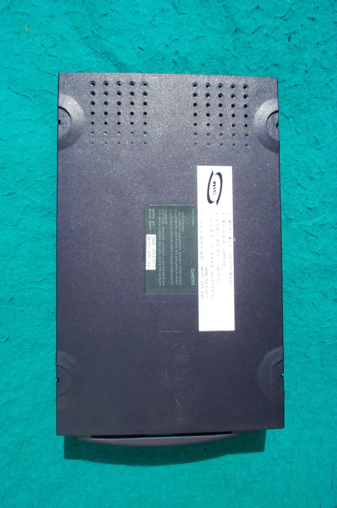
SK TECH CO., LTD. Page 1 of 2 SKT SKTOS-00126 FCC ID : XXXMM-BYX101 External Photographs of EUT SK TECH CO., LTD. Page 2 of 2 SKT SKTOS-00126 FCC ID : XXXMM-BYX101
SK TECH CO., LTD. Page 1 of 1 SKT SKTOS-00126 FCC ID : XXXMM-BYX101 FCC ID Label Sample
SK TECH CO., LTD. Page 1 of 1 SKT SKTOS-00126 FCC ID : XXXMM-BYX101 FCC ID Sample Label & Location Information LABELLING REQUIREMENTS PER ∫∫∫∫ ∫∫∫∫∫∫∫∫ ∫∫∫∫2.928 The Label shown shall be permanently affixed at a conspicuous location on the device and be readily visible to the user at the time of purchase. FCC ID : PAHMM-BYX101 This device complies with part 15 of the FCC Rules. Operation is subject to the following two conditions: (1) This device may not cause harmful interference, and (2) this device must accept any interference received, including interference that may cause undesired operation.
SK TECH CO., LTD. Page 1 of 3 SKT SKTOS-00126 FCC ID : XXXMM-BYX101 Internal Photographs of EUT SK TECH CO., LTD. Page 2 of 3 SKT SKTOS-00126 FCC ID : XXXMM-BYX101 SK TECH CO., LTD. Page 3 of 3 SKT SKTOS-00126 FCC ID : XXXMM-BYX101
SK TECH CO., LTD. Page 1 of 2 SKT SKTOS-00126 FCC ID : XXXMM-BYX101 Operational Description Section 1: Hardware set up A. Connecting to the MOMOBay a. Connect DC Adapter. The adapter is for both 110V/220V. b. Connect 1394 Cable to PC and 1394 port of the MOMOBay. c. Insert the Bay Module. d. The buzzer will go off when it is normal. At this point, switch the key and the power will be supplied to the Bay module. B. Exchanging the HDD in Bay Module a. Lift the handle of the Bay Module up, pull the switch gently and the cover of the Bay Module will be opened. b. Connect the Flat Cable and the power cord to the HDD. The jumper must be selected on master.(refer to the proper HDD manual for selecting the jumper) c. Connect the HDD cable and the HDD power. Insert from the back of the HDD. C. Inserting/extracting the Bay Module to the MOMOBay 1) Insert the Bay Module to the Bay. 2) When the Bay Module is properly inserted, the buzzer will go off and the power indicator LED will be flashing. 3) Turn the Safety Key on and the power will be supplied to the Bay Module. The buzzer will go off for about 1 second. 4) If there is a problem to the power supply, the power will be cut off and the buzzer will og off. In this case, turn the Safety Key off and the Bay Module can be safely extracted. Contact the purchasing dealer or our A/S center. 5) It will take about 6 to 12 seconds(spin up time)for the OS to detect HDD and Indicate the new drive after turning the Safety Key on. 6) When extracting the Bay Module, turn the Safety Key off, shut the power off and extract the Bay Module. In normal case, the buzzer will go off for 1 second. Wait until the buzzer stops, then extract the Module. 7) When the PC is accessing to the Bay Module, the Bay Module will be shut off but The error sound will go off. In this case, turn the Safety Key on and wait until the data has been fully transmitted before turning it off again. 8) The Bay module can be extracted without turning the power of the MOMOBay or SK TECH CO., LTD. Page 2 of 2 SKT SKTOS-00126 FCC ID : XXXMM-BYX101 the PC off. (Hot Swap function) A. Windows 98SE In Windows 98SE, execute the Set Up Program of the Set Up CD provided by our Company under the Windows directory and reboot the system. B. Windows Me and above Win2000 Since the OS supports drive itself, other setup is unnecessary. C. MAC(above OS 8.5) 1) Execute DviCO_ Sample_ Driver.sit file under Mac directory using the Set up CD. 2) Copy “Firewire support, Firewire enabler, FWSBP2 DISK driver “ file under DViCO_Sample_Driver folder to expansion file in Hangul system and reboot the system. D. HDD Format 1) Win 98SE a. After the OS has been rebooted, execute Fdisk in Dos Mode and select the Partition of the HDD. b. As to selecting the partition, refer to the OS manual. c. After selecting the new drive, select Format in the property tool to format the HDD. 2) Win2000 You can select Format and Partition in Disk management in Win2000 3) MAC When the HDD, which has not been formatted, is inserted, the icon will indicate Whether the disk will be formatted or not. Select OK at this point.
SK TECH CO., LTD. Page 1 of 13 SKT SKTOS-00126 FCC ID : XXXMM-BYX101 Certificate of Compliance Test Report No.: SKTOS-00126 NVLAP CODE : 200220-0 Applicant: DVICO INC. Applicant Address: Kookmin card B/D 267-2, Seohyun-dong, Boondang-gu, Sungnam-si, Kyungki-Do, 463-050, Korea Product: Momo Bay BX1 FCC ID: PAHMM-BYX101 Serial No.: N/A Receipt No.: SKE20000829-646 Date of receipt: Aug. 29, 2000 Date of Issue: Oct. 04, 2000 Testing location: SK TECH CO., LTD. 820-2, Wolmoon-Ri, Wabu-Up, Namyangju-Si, Kyunggi-Do, Korea Test Standards: ANSI C63.4 / 1992 Rule Parts: FCC part 15 Subpart B Equipment Class : Class B Digital Device Peripheral Test Result: The above mentioned product has been tested and passed. Prepared by:Y.H. Kang Tested by:K.H.Nam/Engineer Approved by: J.Y.Hyun /Lab.Manager Signature Date Signature Date Signature Date Other Aspects : Abbreviations : · OK, Pass = passed · Fail = failed · N/A = not applicable ☞ ☞☞ ☞ •This test report is not permitted to copy partly without our permission. •This test result is dependent on only equipment to be used. •This test result is based on a single evaluation of one sample of the above mentioned. •This test report must not be used by the client to claim product endorsement by NVLAP or any agency of the U.S Government. • We certify that this test report has been based on the measurement standards that is traceable to the national or International standards. NVLAP Lab. Code: 200220-0 SK TECH CO., LTD. Page 2 of 13 SKT SKTOS-00126 FCC ID : XXXMM-BYX101 》》 》》》》 》》 Contents 《《 《《《《 《《 Contents 2 List of Tables 2 List of Figures 2 List of Photographs 2 1. General 3 2. Test Site 3 2.1 Location 3 2.2 List of Test and Measurement Instruments 4 2.3 Test Data 4 2.4 Test Environment 4 3. Description of the tested samples 5 3.1 Rating and Physical characteristics 5 3.2 Submitted documents 5 4. Measurement conditions 6 4.1 Modes of operation 6 4.2 List of Peripherals 6 4.3 Type of Used cables 7 4.4 Test Setup 7 4.5 Uncertainty 7 5. Emission Test 8 5.1 Conducted Emissions 8 5.2 Radiated Emissions 12 》 》》 》List of Tables Table 1 List of test and measurement equipment 4 Table 2 Test Data, Conducted Emissions 11 Table 3 Test Data, Radiated Emissions 13 》 》》 》List of Figures Figure 1 Spectral Diagram, LINE-PE 9 Figure 2 Spectral Diagram, Neutral-PE 10 SK TECH CO., LTD. Page 3 of 13 SKT SKTOS-00126 FCC ID : XXXMM-BYX101 1. General This equipment has been shown to be capable of compliance with the applicable technical standards and was tested in accordance with the measurement procedures as indicated in this report. We attest to the accuracy of data. All measurements reported herein were performed by SK Tech Co., Ltd. and were made under Chief Engineer’s supervision. We assume full responsibility for the completeness of these measurements and vouch for the qualifications of all persons taking them. 2. Test Site SK TECH Co., Ltd. 2.1 Location 820-2, Wolmoon Ri, Wabu-Up, Namyangju-Si, Kyunggi-Do, Korea The test site is in compliance with ANSI C63.4/1992 for measurement of radio interference. SK TECH CO., LTD. Page 4 of 13 SKT SKTOS-00126 FCC ID : XXXMM-BYX101 2.2 List of Test and Measurement Instruments Table 1 : List of Test and Measurement Equipment ! Conducted Emissions Kind of Equipment Type S/N Calibrated until Field Strength Meter ESHS 10 862970/019 04.2001 LISN KNW-407 M63284 07.2001 LISN ESH2-Z5 862060/029 06.2001 Conducted Cable N/A N/A 07.2001 ! Radiated Emissions Kind of Equipment Type S/N Calibrated until Field Strength Meter ESVS 10 825120/013 04.2001 Spectrum Analyzer R3361A 11730187 07.2001 Amplifier 8447F 3113A05153 05.2001 Log Periodic Antenna UHALP9107 91071238 04.2001 Biconical Antenna BBA9106 N/A 04.2001 Open Site Cable N/A N/A 07.2001 Antenna Mast 5907 N/A N/A Antenna & Turntable controller 5906 91X519 N/A Amp & Receiver connection cable N/A N/A 07.2001 Amp & Spectrum connection cable N/A N/A 07.2001 50Ω Switcher MP59B M93083 07.2001 2.3 Test Date Date of Application : Aug. 29, 2000 Date of Test : Sep. 19, 2000 ~ Sep. 28, 2000 2.4 Test Environment See each test item’s description. SK TECH CO., LTD. Page 5 of 13 SKT SKTOS-00126 FCC ID : XXXMM-BYX101 3. Description of the tested samples The EUT is Momo Bay BX1. 3.1 Rating and Physical Characteristics • Maximum of 400Mbps of high speed Data transmission (Bandwidth) The interface is faster than 320Mps of UltraWide SCSI, and it maintains the same Transmission rate as the internal HDD. • Supports Hot Swap Since the interface of Bay Module follows IEEE1394I/F standard, which supports Hot Swap, the HDD can be taken out without turning the power off. 3.2 Submitted Documents N/A SK TECH CO., LTD. Page 6 of 13 SKT SKTOS-00126 FCC ID : XXXMM-BYX101 4. Measurement Conditions Testing Input Voltage : AC 120V, 60Hz 4.1 Modes of Operation The EUT was in the following operation mode during all testing; Connecting the EUT to PC’ 1394 card using USB cable. Operating the MPEG file & Monitoring the Monitor. 4.2 List of Peripherals Description Manufacturer Model Name Serial No. FCC ID Personal Computer H.P Brio BA600/550 SG01901646 DoC Monitor Samsung SyncMaster750P PG17HS9U/ADC DoC Printer H.P 2225C 3245S12493 DSI6XU2225 Keyboard H.P SKR-1082B 4DBE021164 GJJSKR-1032BS Serial Mouse Adtec 600 0068213 HQA2VTEAN-3 P/S 2 Mouse Logitech M-S48a LZA00960595 JNZ201213 Joystick Logitech LZS01651409 J-ZA10 DoC Adapter ILAN Elec. F1650K None N/A SK TECH CO., LTD. Page 7 of 13 SKT SKTOS-00126 FCC ID : XXXMM-BYX101 4.3 Type of Used Cables Description Length Type of shield Manufacturer Remark PC power cable 1.8m Non-shield None Monitor power cable 1.2m Non-shield None Adapter cable 1.8m Non-shield None Video interface cable 1.2m Shield None Printer AC power cable 1.8m Non-shield None Mouse interface cable 1.5m x2 Non-shield None Keyboard interface cable 1.5m Non-shield None USB interface cable 1.2m Shield None Joystick cable 1.0m Non-shield None 4.4 Test Setup The test setup photographs showed the external supply connections and i…
Text truncated - open the document above for the full version.
SK TECH CO., LTD. Page 1 of 2 SKT SKTOS-00126 FCC ID : XXXMM-BYX101 Test set up photos Photograph 1: Setup for Conducted Emissions SK TECH CO., LTD. Page 2 of 2 SKT SKTOS-00126 FCC ID : XXXMM-BYX101 Photograph 2: Setup for Radiated Emissions
| # | Rule Parts | Frequency Range | Power Output |
|---|---|---|---|
| 1 | 15B | - | - |

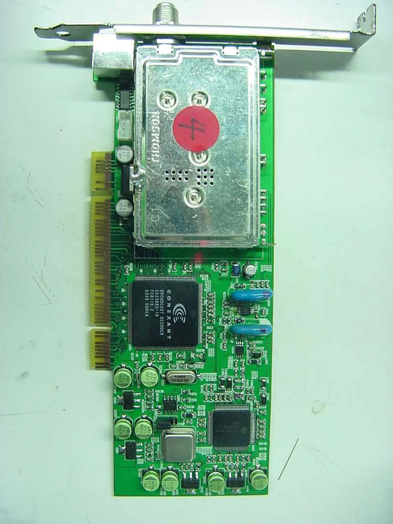
Digital TV Receiver Card
Equipment Class
JBP - Part 15 Class B Computing Device Peripheral