PC8-TX-201Run Safe Tire Pressure Warning System
Sensor Technology International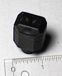
Click to zoom
Application Details
- Equipment Class
- DSC - Part 15 Security/Remote Control Transmitter
- Date of Grant
- Feb 06, 2001
- Application Purpose
- Original Equipment
- Date of Application
- Nov 27, 2000
- Equipment Note
- Run Safe Tire Pressure Warning System
- Frequency Range
- 433.92000000 - 433.92000000
- Country
- United States
Documents & Files
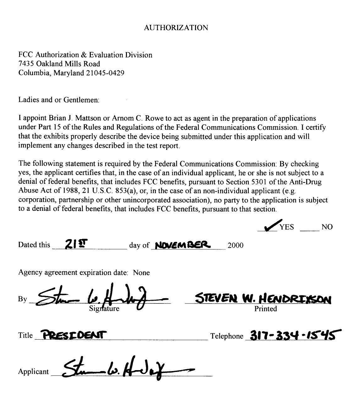
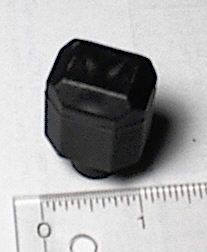
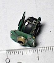
Document Text
Text extracted from the exhibit documents filed with the FCC. Open a document above to read the original.
Block Diagram
Mod ulation Data (Output)
Operational Description
FCC ID: PC8-TX-201 Description of Operation Clarification In the Description of Operation (previously submitted) it says “At thirty (30) second intervals the sensor will read the pressure and compare it to the pressure stored in memory....” In Part 15.231(a) it says “Periodic transmissions at regular predetermined intervals are not permitted....” The description should be clarified by stating that the device is placed directly on the valve stem of the tire and monitors the pressure internally. It only transmits to the receiver/display if there is a fault. It does not transmit at 30 second intervals. The description also states that this device transmits (an A-OK signal) to the receiver/display at 12 hour intervals. This signal tells the operator that the sensor is still operating correctly. FCC Part 15.231(a) says “...polling or supervision of transmissions to determine system integrity of transmitters used in security or safety applications are allowed.” Since this device monitors a vehicle’s tire pressure, it is used in safety applications, allowing the transmission once every twelve hours. I hope this clarifies the operation of this device and shows that it does meet the operational requirements specified in 15.231(a). Correspondence Reference Number: 17911 731 Confirmation Number: EA99375
Parts List/Tune Up Info
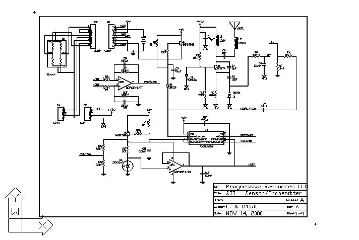
Progressive Resources LLC11/14/00 TYPEVALSHAPEQTYMFGMPN BATTBatteryCoin-Stack1RAYOVACBR1632R CAP5pFSM08051PANASONICECU-V1H050CCN CAP12pFSM08051PANASONICECU-V1H120CCN CAP3pFSM08051PANASONICECU-V1H030CCN CAP100pFSM08051PANASONICECU-V1H101JCG CAP0.01uFSM06035PANASONICECJ-1VB1H103K CAP0.01uFSM08051PANASONICECJ-2VB1H103K CAP0.1uFSM08052PANASONICECJ-2VB1C104K CONN4-PINTH1MILL-MAX850-10-004-20-001 CONN8-PINTH1MILL-MAX850-10-008-20-001 DIODE1N914MINI-MELF1 MICRO SEMIDL4148 TRANSBFS17PSOT23bec1PHILIPS/SEIMENSBFS17P TRANSMMBT3906SOT23bec2MOTOROLAMMBT3906 RES10 ohmSM08051PANASONICERJ-6GEYJ10 RES220 ohmSM08051PANASONICERJ-6GEYJ221 RES1K ohmSM06031PANASONICERJ-3GSYJ102V RES6.81K ohmSM06034PANASONICERJ-3EKF6.81KV RES6.8K ohmSM08051PANASONICERJ-6GEYJ6.8K RES10K ohmSM06036PANASONICERJ-6GEYJ10K RES10K ohmSM08051PANASONICERJ-3GSYJ103V RES15K ohmSM08051PANASONICERJ-3GSYJ153V RESxxxK ohmSM06032PANASONICERJ-3EKFxxxKV SENSORSENTIR1customer supplied ICMCP602-I/STTSSOP81MICROCHIPMCP602-I/ST ICPIC12C672SO81MICROCHIPPIC12C672-04 I /SM ICZRA250F01SOT231ZETEXZRA250F01 IND15nHSMT1 COILCRAFT1008CS-15nH IND150nHSMT1 COILCRAFT1008CS-150nH SAWRO2101SMT1 RF MONOLITHICSRO2101A VARACBBY31SOT231PHILIPS/SEIMENSBBY31 STI Transducer / Transmitter REFDES B1 (SPECIAL) C2 C6 C7 C1 C3 C8 C10 C11 C12 C4 C5 C9 P2 (P4) P1 (P3) D1 Q2 Q1 Q3 R5 R11 R17 R8 R9 R16 R18 R2 R1 R3 R6 R13 R14 R15 R4 R10 R7 R12 (Adjust for HIGH or LOW pressure sensor) U1 (wire bonded to pcb) U2 U3 U4 L1 L2 X1 Z1
Test Report
EMC Test ServicesReport No. 8640 1250 Peterson Drive, Wheeling, Illinois 60090, USA11/28/00 Page 1 TEST SPECIFICATION: FCC "Rules and Regulations", Part 15, Subpart C Sections 15.231 (a-d), 15.207 & 15.205 Intentional Radiators Periodic operation in the band 40.6 – 40.77 MHz & above 70 MHz THE FOLLOWING MEETS THE ABOVE TEST SPECIFICATION Formal Name:Run Safe Tire Pressure Warning System Kind of Equipment:Transmitter Test Configuration:NA Transmitter FCC ID:PC8-TX-201 Model Number: TX-201 Serial Number: NA Dates of Test:September 21 & November 13, 2000 Test Conducted For:Sensor Technology International 5336 West 79th Street Indianapolis, Indiana 46268 NOTICE:Please see change information listed inside of this report. This report must not be used by the customer to claim product endorsement by NVLAP or any agency of the United States Government, and it cannot be reproduced (except in full), without the approval of D.L.S. Electronic Systems Inc. EMC Test ServicesReport No. 8640 1250 Peterson Drive, Wheeling, Illinois 60090, USA11/28/00 Page 2 SIGNATURE PAGE Report Written By: Arnom C. Rowe Test Engineer EMC-001375-NE Report Reviewed by: Jack Prawica Lab Manager Report Approved by: Brian J. Mattson General Manager Company Official: Sensor Technology International EMC Test ServicesReport No. 8640 1250 Peterson Drive, Wheeling, Illinois 60090, USA11/28/00 Page 3 NVLAP Certificate of Accreditation available upon request. EMC Test ServicesReport No. 8640 1250 Peterson Drive, Wheeling, Illinois 60090, USA11/28/00 Page 4 NVLAP Certificate of Accreditation available upon request. EMC Test ServicesReport No. 8640 1250 Peterson Drive, Wheeling, Illinois 60090, USA11/28/00 Page 5 NVLAP Certificate of Accreditation available upon request. EMC Test ServicesReport No. 8640 1250 Peterson Drive, Wheeling, Illinois 60090, USA11/28/00 Page 6 1.Cover Pagei 2.Signature Pageii 3.NVLAP Certificate of Accreditationiii 6.Table of Contentsiv 8.Summary of Test Report1.0 8.Introduction2.0 8.Object3.0 8.Test Set-up4.0 9.Test Equipment (Bandwidths and Detector Function)5.0 9.Conducted Emission Measurements6.0 10.Conducted Emission Data taken during testing6.0 11.Conducted Emission Graphs taken during testing6.0 12.Field Strength of Spurious Emission Measurements7.0 14.Radiated Data taken for Fundamental & Spurious Emissions Measurements7.0 19.Radiated Graphs taken for Fundamental & Spurious Emissions Measurements 7.0 28.Pulsed Operation (Duty Cycle Correction Factor)8.0 29.Pulse Operation Graphs taken during testing8.0 30.Bandwidths9.0 31.Graphs taken of Fundamental Frequency & Bandwidths9.0 33.Restricted Bands10.0 EMC Test ServicesReport No. 8640 1250 Peterson Drive, Wheeling, Illinois 60090, USA11/28/00 Page 7 34.Photo Information and Test Set-Up11.0 35.Photos Taken During Testing12.0 37.Change Information13.0 39.Results of Tests14.0 39.Conclusion15.0 40.Equipment ListTABLE 1 EMC Test ServicesReport No. 8640 1250 Peterson Drive, Wheeling, Illinois 60090, USA11/28/00 Page 8 1.0SUMMARY OF TEST REPORT It was found that the Run Safe Tire Pressure Warning System S/N NA meets the radio interference emission requirements of the FCC "Rules and Regulations", Part 15, Subpart C, Sections 15 .231 (a-d), 15.207 and 15.205 for Intentional Radiators operating in the bands 40.66 to 40.77 MHz and above 70 MHz with periodic operation. NOTE: The conducted emissions test was not required because the EUT is powered from a DC power source. It does not have a line cord to plug into the A.C. power line. 2.0INTRODUCTION On September 21 & November 13, 2000, a series of radio frequency interference measurements were performed on Transmitter, S/N NA. The tests were performed according to the procedures of FCC as stated in MP-1 “FCC Methods of Measurement for determining Compliance of Radio Control and Security Alarm Devices and Associated Receivers”. Tests were performed by personnel of D.L.S. Electronic Systems, Inc. who are responsible to Donald L. Sweeney, Senior EMC Engineer. 3.0OBJECT The purpose of this series of tests was to determine if the test sample could meet the radio frequency emission requirements of the FCC "Rules and Regulations", Part 15, Subpart C, Sections 15.231 (a-d), 15.207 and 15.205 for Intentional Radiators operating in the bands 40.66 to 40.77 MHz and above 70 MHz Frequency Band with periodic operation. 4.0TEST SET-UP All radiated emission tests were performed at D.L.S. Electronic Systems, Inc. The radiated tests were made with the test item placed on a non-conductive turntable located in the Test Room with the receive antenna placed three meters from the device under test. The equipment under test was set up according to ANSI C63.4-1992, Section 8, (Figures 9c and 9d). EMC Test ServicesReport No. 8640 1250 Peterson Drive, Wheeling, Illinois 60090, USA11/28/00 Page 9 5.0TEST EQUIPMENT (Bandwidths and Detector Function) All preliminary data below 1000 MHz was automatically plotted using the Peak or CISPR Detector Functions. This information was then used to determine the frequencies of maximum emissions. Manual measurements were performed on these frequencies using a peak detector function of the Receiver with the bandwidths specified by the FCC. Above 1000 MHz final data was taken using the Peak Detector. Below 1000 MHz final data was taken using the fixed tuned receiver. Plots were made using the Peak Detector, with manual measurements made on the frequencies of interest, using the Peak, CISPR, and Average Detector Functions of the receiver. When average measurements were made using the fixed tuned receiver, the average was taken of a linear IF signal as specified by FCC and ANSI C63.4-1992. The fundamental frequency was measured using the Average Detector and the CISPR Detector was used for measuring the Harmonics as stated in Section 15.209. From 10 kHz to 30 MHz a bandwidth of 9 kHz was used. From 30 MHz to 1000 MHz a bandwidth of 120 kHz was used and above 1000 MHz, a bandwidth of 1 MHz was used to ensure proper…
Text truncated - open the document above for the full version.
Contact Information
Applicant
Steven W Hendrixson(President)
Technical Contact
DLS Electronic Sysyems, Inc.Arnom C Rowe
[email protected]847-537-6400
1250 Peterson Drive · Wheeling, Illinois · United States
Non-Technical Contact
Sensor Technology InternationalSteven W Hendrixson
[email protected]317-334-1545
Test Firm
DLS Electronic Systems, Inc.William Stumpf
Technical Specifications
| # | Rule Parts | Frequency Range | Power Output | Emission | Tolerance |
|---|---|---|---|---|---|
| 1 | 15C | 433.92 MHz - 433.92 MHz | - | NA | Hz |