PCZ1100Pegasus Active Triple Field Antenna
ATL Agricultural Technology Ltd.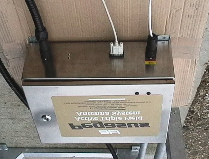
Click to zoom
Application Details
- Equipment Class
- DCD - Part 15 Low Power Transmitter Below 1705 kHz
- Date of Grant
- Jan 21, 2001
- Application Purpose
- Original Equipment
- Date of Application
- Nov 23, 2000
- Equipment Note
- Pegasus Active Triple Field Antenna
- Frequency Range
- 0.13420000 - 0.13420000
- Country
- United Kingdom
Documents & Files
Document Text
Text extracted from the exhibit documents filed with the FCC. Open a document above to read the original.
Attestation Statements
(c) ATL Agricultural Technology Ltdwww.agricultural-technology.co.uk Attestation Statements Product: ATL Pegasus Active Triple Field Antenna FCC ID Number: PCZ 1100 Company: ATL Agricultural Technology Limited Address: Place Farm, Kirtling, Suffolk. CB8 9PA. United Kingdom Grantee Code: PCZ FCC Reg. No.: FRN 0003-7397-86 Contact Details: Contact: Jason Sharp Position: Technical Designer Telephone: +44 (0) 1638 731212 Facsimile: +44 (0) 1638 731174 Email: [email protected] Product Description: The transmitter is an livestock transponder reading system based on the Texas Instruments ‘TIRIS’ tag reader module. The system comprises a control box and an antenna. The control box contains a power regulation circuit and the tag reading module. The antenna is a cubic structure designed to allow an animal to walk through it. The antenna may be made from either galvanised or stainless steel. Applicable Standard: 47CFR PART 15 - Non-Licensed Transmitter/Intentional Radiator Compliance Testing: The system was fully tested against applicable FCC regulations and a full test report was compiled. Test House: dB Technology (Cambridge Ltd.) 23 Headington Drive, Cambridge. CB1 4HE. United Kingdom Telephone: +44 (0) 1954 251974 Facsimile: +44 (0) 1954 251907 Email: [email protected] Contact: Dave Smith Jason Sharp - Technical Designer Robin Sadler - Managing Director
Block Diagram
(c) ATL Agricultural Technology Ltdwww.agricultural-technology.co.uk
Cover Letter(s)
(c) ATL Agricultural Technology Ltdwww.agricultural-technology.co.uk Product Technical Specification Company: ATL Agricultural Technology Limited, Kirtling, Suffolk. CB8 9PA United Kingdom. Tel: (01638) 731212 Fax: (01638) 731174 email: [email protected] web site: www.agricultural-technology.co.uk Product: Pegasus Active Triple Field Antenna System Description: Purpose built ‘portal’ antenna system linked to Texas TIRIS low frequency, half duplex transponder reader module with communications interface. Transmitting mode: Burst Sequential FM (fsk) system with 20KHz bandwidth. Charge burst of 50mS followed by read period and sync period of 40 mS. Frequency: 134.2 KHz Mains Connection: 4 pin circular type with Live, neutral and earth connections Operating Line Voltage: 115 volt AC mains Mains Frequency: 50/60Hz Mains Power: 20 watts maximum Mains Fuse Rating: T1A, 20mm Glass Low Volts Fuse Rating: F2A, 20mm Glass Antenna Connection: 7 pin weatherproof circular type. Antenna Size: Antenna size is approx.1.89m high, 1.02m wide & 1.33m long. Antenna Weight: Approx. 78 Kg Antenna Conduit Length: 3000mm Control Box: Stainless Steel enclosure approx. 400mm x 300mm x 150mm Control Box Weight: Approx. 10.5 Kg Comms. Protocol: RS232-C Communications Interface Comms. Connection: Standard 9 pin ‘D’ chassis socket (weatherproof) with Rx, Tx and Gnd connections. Operating Temperature: 0 to +70 degrees C Storage Temperature: -25 to +85 degrees C
Cover Letter(s)
(c) ATL Agricultural Technology Ltdwww.agricultural-technology.co.uk Modifications During the approval testing of the Pegasus Active Triple Field Antenna system modifications were made at the test house to ensure compliance. These are detailed below: 1. Mains input filter was moved so that it is placed next to the mains input connector. This ensures a minimal length of wiring between the connector and filter inside the main control enclosure. 2. The screens of the coaxial antenna cables as they enter the control box enclosure were strapped to the enclosure wall with a clamp close to the antenna connector. This ensures the electrical integrity of the enclosure. 3. The use of a good quality screened lead for the RS232-C data connection between the externally mounted interface port and any connected data collector or computer. This cable would be supplied by the end user and a note stating this will be included in the user manual that accompanies the device. These modifications are detailed in the relevant product production documents. The modifications noted in items 1 and 2 will be implemented in all production units Robin Sadler Managing Director
Cover Letter(s)
www.agricultural-technology.co.uk A. T. L. Agricultural Technology Limited Place Farm, Kirtling, Suffolk. CB8 9PA 29th November 2000 Confidentiality Request Pursuant to 47CFR0.457 and 0.459 Dear Sirs, Two exhibits have been sent to you for the following submission: FCC ID: PCZ1100 Form 731 Confirmation No.: EA99355 Product: Pegasus Active Triple Field Antenna These exhibits, schematics for the reader module, have been deemed as confidential by our supplier. The ‘confidential’ box was checked when the exhibits were uploaded. We request that these exhibits are not made routinely available for public inspection. Please note the following with regard to the reasons that confidentiality is sought: 1. The two specific exhibits are identified as RF Schematic One and RF Schematic Two and were uploaded as ‘schematics’ on 27th November 2000. They are the schematic circuit diagrams for Texas Instruments RFID Systems S2000 reader. 2. They have been submitted to the FCC as part of an approval against CFR47 Part 15 for a non-licensed transmitter/intentional radiator with the FCC ID, confirmation number and description as shown above. 3. The information is of a technical nature and is considered to be a trade secret by the owner, Texas Instruments. 4. The information does not relate to a service that is subject to competition. It relates to hardware that is designed by and proprietary to Texas Instruments. 5. Novel aspects in the design of the circuitry would, if disclosed, give an advantage to TI’s competitors in the field of RFID 6. The submitting party, ATL Agricultural Technology Limited, have not seen this information. It was sent to an authorised third party, the test house, who signed a Non-Disclosure Agreement and uploaded the information to the FCC site. It was uploaded with the ‘confidential’ box ‘ticked’. Texas Instruments only releases this information after a Non-Disclosure Agreement has been signed by the recipient of the information. In addition, the information that was passed to the test laboratory in soft copy was password protected. 7. Texas Instruments has only released this information to third parties after a Non-Disclosure Agreement has been signed by the intended recipient, and then only on a need to know basis. 8. Texas Instruments determines that 5 years from the date of disclosure is appropriate to protect is proprietary ownership of the information, and maintain its competitive advantage with respect to RFID reader design. 9. Texas Instruments vigorously protects its intellectual property, and derives a significant stream of revenue from the protection of its leading edge IP. Unprotected disclosure of such IP, of which this information is a part, would damage TI’s ability to protect its IP in the future, and would lessen TI’s ability to obtain a return on its significant investment in this technology. Yours faithfully Jason Sharp ATL Agricultural Technology Limited
External Photos
(c) ATL Agricultural Technology Ltdwww.agricultural-technology.co.uk Pegasus Active Triple Field Antenna Pegasus Control Box (c) ATL Agricultural Technology Ltdwww.agricultural-technology.co.uk Antenna Connected to Control Box Below: Control box showing: 1. Antenna connection (left) 2. RS232-C interface connection (middle) 3. Mains input (right) (c) ATL Agricultural Technology Ltdwww.agricultural-technology.co.uk Antenna Connector - 7 Pin Circular, Weatherproof Connector.
ID Label/Location Info
(c) ATL Agricultural Technology Ltdwww.agricultural-technology.co.uk Actual Size FCC ID Label Size : 88mm (width) 134mm (height) Material : Transparent Film Printing : Inkjet on rear surface Adhesive : Acrylic Structural Adhesive Label Position : Left hand end of stainless steel control box enclosure. (c) ATL Agricultural Technology Ltdwww.agricultural-technology.co.uk Actual Size Antenna Identification Label Size : 91mm (width) 38mm (height) Material : White Polyester Printing : Indelibly Laser Printer Adhesive : Self Adhesive Label Position : Inside of conduit protection shield.
Internal Photos
(c) ATL Agricultural Technology Ltdwww.agricultural-technology.co.uk PSU152B Power Supply PCB Component side view PSU152B Power Supply PCB Track side view (c) ATL Agricultural Technology Ltdwww.agricultural-technology.co.uk WLK148D Multiplex PCB Component side view WLK148D Multiplex PCB Track side view (c) ATL Agricultural Technology Ltdwww.agricultural-technology.co.uk Texas Instruments TIRIS Low frequency half-duplex transponder reader module complete module - top view comprises two pcbs: RF module at top and Control module underneath RF module Top view with metal shield removed (c) ATL Agricultural Technology Ltdwww.agricultural-technology.co.uk RF module bottom view with metal shield removed Control module top view (c) ATL Agricultural Technology Ltdwww.agricultural-technology.co.uk Control module bottom view Control module bottom view with software PCB removed (c) ATL Agricultural Technology Ltdwww.agricultural-technology.co.uk Complete control chassis top view with: multiplex and tuning coil module on left power supply and reader module on right Completye control chassis with multiplex module lid removed showing tuning inductor and multiplex PCB at bottom (c) ATL Agricultural Technology Ltdwww.agricultural-technology.co.uk Control Box with complete chassis removed Control Box Top view with lid open (c) ATL Agricultural Technology Ltdwww.agricultural-technology.co.uk Control Box Inside of lid showing LED PCB Control Box Detail of earth terminal next to lid hinge (c) ATL Agricultural Technology Ltdwww.agricultural-technology.co.uk Antenna Wiring showing connections at corner Antenna wiring showing capacitor added for balancing
Operational Description
(c) ATL Agricultural Technology Ltdwww.agricultural-technology.co.uk Operational Description System Overview The system is used as an electronic tag reading system for animal identification purposes on farms, markets/sales and abattoirs. This design is used for identifying cattle whilst they move along passageways. Each animal to be identified must be tagged with a low frequency half-duplex transponder. These are usually in the form of ear tags. The system comprises a ‘walkthrough antenna and a control box. The antenna is a cubic structure made from either galvanised or stainless steel tubes. This antenna structure houses three pairs of transmit/receive loop antennae. These are connected to the control box via coaxial cables. The control box is a stainless steel enclosure housing a power supply circuit, the TIRIS tag reader module and the antenna multiplex circuit. The box also has connections for line voltage and communications data. During operation a tagged animal walks through the antenna. The reader module transmits a carrier to the tag which uses this signal to charge an internal capacitor. When sufficient charge is built up, the tag responds to the reader module with a unique identity code. The reader module then decodes this and outputs it via the RS232-C communications interface. This can then be captured by a computer. System Breakdown The complete system comprises four individual blocks of circuitry. The operation of each of these blocks is described below: Power Supply The line voltage of 115VAC is first filtered and fused. It is then transformed to 15 volts by a 50 VA isolation transformer. The 15 volts AC is then rectified and smoothed before being regulated to a steady 13.6 volts DC. (for the reader module). TIRIS Reader Module The reader module is a commercially available tag reading system from Texas Instruments. It works on a half duplex system whereby it continually switches between transmit and receive modes. The transmission burst at 134.2KHz lasts for 50 ms. This is followed by a receive period of 20mS and then a wait/sync period of 20mS. The transmission is used as a charge burst to charge the animal tag’s internal storage capacitor. When charged, the tag responds, by which time the reader has switched to receive mode. The tag responds with 134.2KHz signal that is frequency modulated with a unique identity code using frequency shift keying (fsk) with a bandwidth of 20KHz. The reader has an RS232-C communications interface port used to transfer the tag code to an external computer. The reader has two status indicators that are mounted on the front panel of the control box. The red LED flashes on whenever the reader goes into transmit mode. Under normal operation this LED flashes at a rate of approx. ten a second. The green LED flashes once for each successful tag read. The antenna pairs are matched to the reader output by the addition of the parallel tuning coil. The coil has an adjustable ferrite slug that enables each system to be individually tuned to give maximum performance. (c) ATL Agricultural Technology Ltdwww.agricultural-technology.co.uk Multiplex Circuit The single antenna output from the reader module must be switched continually between the three pairs of antennas. This is done by taking the ACTIVE pulse signal from the reader module and dividing it by three using a divider logic chip. These three sequential outputs are then used to sequentially turn on three separate opto-isolated MOSFET switches. Each of these MOSFETs switches a pair of antennas. The opto MOSFETs are paired in parallel to cut down on signal losses. Antenna The antenna consists of three pairs of parallel loops. Each of the pairs is switched on in turn via the multiplex circuit and the opto MOSFETs. This ensures that whichever orientation the tag is in it will be read by at least one pair of antennas.
Parts List/Tune Up Info
(c) ATL Agricultural Technology Ltdwww.agricultural-technology.co.uk Tuning Information The system works at a fixed frequency that cannot be changed. The only tuning available ensures that the inductance of the antenna system matches the output of the reader module. This tuning is achieved with an adjustable inductor connected into the circuitry between the reader and the antenna. The antennas and controls are manufactured and tested separately, so they are not shipped as a matched pair. This means that during installation the control must be tuned to match the attached antenna to give the best performance. The antennas and controls are all built to within a small tolerance and the tuning required will be minimal. A volt meter is required to tune the control system. The volt meter, on the 200 volt DC range is connected to the each of the test pins on the left hand side of the multiplex module in turn. The antenna must be attached to the system and the mains turned on. Tuning is done by slowly turning the tuning inductor control knob on the tuning inductor either clockwise or anti clockwise until the average voltage on each of the test pins is a maximum. A tag can then be used to test the system to ensure reading is adequate. Three tests can be carried out to verify the performance: 1. Approach the antenna either from the side or end with the transponder held so that it is aligned with the axis of the side or end being approached. The distance from the antenna at which the tag is first read should be about 600mm (2ft). 2. Hold a transponder at the mid point of the side just inside rail with the transponder oriented front to back. The ‘no read’ window should be relatively small, no more than a triangle 100mm along and 100mm inwards at the centre point of the side rails. 3. Hold a transponder tag at the centre of the antenna framework. It should be possible to rotate the transponder in all directions whilst it is being read. At an angle of 45 degrees to each of the three antenna pairs it should be read continuously by all three antenna pairs. This is indicated by a rapid, even flashing of the read OK LED.
Test Report
|---------- ( Cambridge Ltd. ) ----------| Testing EMCEMC Consultancy EMC Training or : 01223 241140 (accounts) 23, Headington Drive, Cambridge. CB1 4HE Tel : 01954 251974 (test site) Fax : 01954 251907 email: [email protected] web : www.dbtechnology.mcmail.com REPORT ON ELECTROMAGNETIC COMPATIBILITY TESTS Performed at: TWENTY PENCE TEST SITE Twenty Pence Road, Cottenham, Cambridge U.K. CB4 4PS on Agricultural Technology Ltd. Pegasus Walk Through Antenna dated 17 October 2000 1 of 22 Page: Test Report T0284 Test No: FCC ID: PCZ1100 R1321 Report No: dB Technology (Cambridge) Ltd. Equipment Under Test (EUT):Pegasus Walk Through Antenna Test Commissioned by:Agricultural Technology Ltd. Place Farm Kirtling Newmarket Suffolk CB8 9PA Representative:Jason Sharp Test Started:28 September 2000 Test Completed:29 September 2000 Test Engineer:Dave Smith Date of Report:17 October 2000 Report: Written by:Dave SmithChecked by:Derek Barlow Signature:D.A.SmithSignature:D.Barlow Date:21 November 2000Date:21 November 2000 Test Standards Applied CFR 47 : 1999 Code of Federal Regulations: Pt 15 Subpart C - Radio Frequency Devices - PASS Intentional Radiators 2 of 22 Page: Test Report T0284 Test No: FCC ID: PCZ1100 R1321 Report No: dB Technology (Cambridge) Ltd. Emissions Test Results Summary CFR 47 : 1999PASS TestPortMethodLimitPASS/FAILNotes Conductedac powerANSI C63.4:1992FCC_CPASS Emissions Radiated ANSI C63.4:1992FCC_CPASS Emissions 3 of 22 Page: Test Report T0284 Test No: FCC ID: PCZ1100 R1321 Report No: dB Technology (Cambridge) Ltd. Contents 22 PLOT 8 Radiated Emissions (250MHz to 1GHz) ........................................... 21 PLOT 7 Radiated Emissions (25MHz to 275MHz) .......................................... 20 PLOT 6 Radiated Emissions (4MHz to 30MHz) ............................................ 19 PLOT 5 Radiated Emissions (100kHz to 4.7MHz) .......................................... 18 PLOT 4 Conducted Emissions - Neutral (Galvanised) ....................................... 17 PLOT 3 Conducted Emissions - Live (Galvanised) .......................................... 16 PLOT 2 Conducted Emissions - Live (Stainless Steel) ....................................... 15 PLOT 1 Conducted Emissions - Neutral (Stainless Steel) ..................................... 14 4.4 Radiated Emissions Results (above 30MHz) ............................................ 13 4.3 Radiated Emissions Results - Intentional Transmitter - Galvanized Steel ..................... 12 4.2 Radiated Emissions Results - Intentional Transmitter - Stainless Steel ....................... 11 4.1 Conducted Emission Results .......................................................... 10 4 Test Results ......................................................................... 10 3.3 Radiated Emissions above 30MHz ..................................................... 9 3.2 Radiated emissions below 30MHz. ....................................................... 9 3.1 Conducted Emissions - ac power ....................................................... 9 3 Test Methods ......................................................................... 8 2 Test Equipment ....................................................................... 7 Figure 1 General Arrangement of EUT and Peripherals ....................................... 6 1.3 EUT Operating Modes ................................................................ 6 1.2 Modifications to EUT and Peripherals ................................................... 5 1.1 General ............................................................................. 5 1 EUT Details ........................................................................... 4 of 22 Page: Test Report T0284 Test No: FCC ID: PCZ1100 R1321 Report No: dB Technology (Cambridge) Ltd. 1 EUT Details 1.1 General The EUT was an Pegasus Walkthrough Antenna System. The system is intended to detect tags on cattle which pass through a steel frame. Loop antennae are incorporated in the frame. A control unit feeds the antenna with a 134.2kHz signal. The results of the detection system may be output to a PC via a serial port. The device was therefore considered as an intentional radiator operating under the rules of CFR 47 subsection C and also a digital device under CFR 47 subsection B. The class B limits for a digital device were applied (although the higher class A limits may be considered more appropriate for the system). Two versions of the system were tested. The only difference between the units was the material used to make the frame which housed the antennae. One version was stainless steel, the other galvanised mild steel. The same controller was used for both units. Details of the EUT and associated peripherals used during the tests are listed below. Figure 1 shows the interconnections between the EUT and peripherals. ItemManufacturerModelDescriptionSerial No:FCC ID 1ATLPegasus System withEUTPCZ1100 galvanized steel frame 2ATLPegasus System withEUTPCZ1100 stainless steel frame 3DellSYS210PCSYS210031921 E2K50YDELL210 4OlivettiDSM 28-142 PSMonitor7072366BEJCY410 5DellSK-1000REWKeyboardM951222710GYUR265K 6LogitechMB-82-950LMouseLT079010452DZL6QBC 7HPDeskjet 850CPrinterSG563160GCB94C2145X 5 of 22 Page: Test Report T0284 Test No: FCC ID: PCZ1100 R1321 Report No: dB Technology (Cambridge) Ltd. 1.2 Modifications to EUT and Peripherals Details of any modifications that were required to achieve compliance are listed below. The modification numbers are referred to in the results sections as appropriate. ModDetails No: 0 Original unit. 1 Mains filter moved next to connector. 2 Screens of co-axial output wires clamped to the case near the connector. 1.3 EUT Operating Modes The EUT was tested in the following operating mode or modes. Generally, operating modes are chosen that will exercise the functions of the EUT as fully as possible and in a manner…
Text truncated - open the document above for the full version.
Test Setup Photos
Contents 6 Photograph 10 Radiated above 30MHz - Back ............................................... 6 Photograph 9 Radiated above 30MHz - Front ............................................... 5 Photograph 8 Radiated below 30MHz - Stainless Unit ......................................... 5 Photograph 7 Radiated below 30MHz - Galvanised Unit ....................................... 4 Photograph 6 Conducted - Stainless Unit Back .............................................. 4 Photograph 5 Conducted - Stainless Unit Front (2) ........................................... 3 Photograph 4 Conducted - Stainless Unit Front (1) ........................................... 3 Photograph 3 Conducted - Galvanised Unit Back ............................................ 2 Photograph 2 Conducted - Galvanised Unit Front (2) ......................................... 2 Photograph 1 Conducted - Galvanised Unit Front (1) ......................................... 1 of 6 Page: Test Photographs T0284 Test No: FCC ID: PCZ1100 R1321 Report No: dB Technology (Cambridge) Ltd. ` Photograph 1 Conducted - Galvanised Unit Front (1) Photograph 2 Conducted - Galvanised Unit Front (2) 2 of 6 Page: Test Photographs T0284 Test No: FCC ID: PCZ1100 R1321 Report No: dB Technology (Cambridge) Ltd. Photograph 3 Conducted - Galvanised Unit Back Photograph 4 Conducted - Stainless Unit Front (1) 3 of 6 Page: Test Photographs T0284 Test No: FCC ID: PCZ1100 R1321 Report No: dB Technology (Cambridge) Ltd. Photograph 5 Conducted - Stainless Unit Front (2) Photograph 6 Conducted - Stainless Unit Back 4 of 6 Page: Test Photographs T0284 Test No: FCC ID: PCZ1100 R1321 Report No: dB Technology (Cambridge) Ltd. Photograph 7 Radiated below 30MHz - Galvanised Unit Photograph 8 Radiated below 30MHz - Stainless Unit 5 of 6 Page: Test Photographs T0284 Test No: FCC ID: PCZ1100 R1321 Report No: dB Technology (Cambridge) Ltd. Photograph 9 Radiated above 30MHz - Front Photograph 10 Radiated above 30MHz - Back 6 of 6 Page: Test Photographs T0284 Test No: FCC ID: PCZ1100 R1321 Report No: dB Technology (Cambridge) Ltd.
Contact Information
Applicant
Jason Sharp(Technical Designer)
Test Firm
DB TechnologyDave Smith
Technical Specifications
| # | Rule Parts | Frequency Range | Power Output |
|---|---|---|---|
| 1 | 15C | 0.1342 MHz - 0.1342 MHz | - |