PD3LENNOVATORRemote Pool/Spa Control System
Len Gordon Company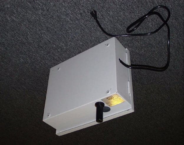
Click to zoom
Application Details
- Equipment Class
- DSR - Part 15 Remote Control/Security Device Transceiver
- Date of Grant
- Jan 07, 2001
- Application Purpose
- Original Equipment
- Date of Application
- Jan 07, 2001
- Equipment Note
- Remote Pool/Spa Control System
- Frequency Range
- 916.50000000 - 916.50000000
- Company
- Len Gordon Company
- Country
- United States
Documents & Files
Document Text
Text extracted from the exhibit documents filed with the FCC. Open a document above to read the original.
Users Manual
OWNERS INSTALLATION & OPERATION MANUAL LENNOVATOR POOL/SPA CONTROL SYSTEM LEN GORDON CO Electronic/Pneumatic Controls & Components 7215 Bermuda Rd Las Vegas 89119-4304 Phone (702) 361-0600 Fax (702) 361-0613 www.gordon-aqualine.com When installing and using this electrical equipment, basic safety precautions should always be followed, including: READ AND FOLLOW ALL INSTRUCTIONS WARNING - RISK OF CHILD DROWNING Extreme caution must be exercised to prevent unauthorized access to the spa by children. WARNING - To reduce the risk of injury, do not permit children to use the spa unless they are closely supervised at all times. WARNING - RISK OF ELECTRICAL SHOCK Install the Control Module at least 5 feet (1.5m) from the inside wall of spa, using non-metallic plumbing. DANGER-RISK OF ELECTRICAL SHOCK Do not permit any electrical appliance, such as a light, telephone, radio or television within 5 feet (1.5m) of the spa. A bonding lug has been provided on the outside of the Control Module electrical control box. This lug permits the connection of a No. 8 AWG (8.4mm²) solid copper bonding conductor between the Control Module and all other electrical equipment and exposed metal within 5 feet (1.5m) of the Control Module. WARNING - To reduce the risk of injury to persons within the spa, never remove, or alter in any way, the grates or covers on the suction fittings in the spa. Never operate the Control Module if the grates or covers on the suction fittings are broken or missing. WARNING - Prolonged immersion in water hotter than 104EF (40EC) may cause hypothermia. The causes, symptoms and effects of hypothermia may be described as follows: Hypothermia occurs when the internal temperature of the body reaches a level several degrees above the normal body temperature of 98.6EF (37EC). The symptoms of hypothermia include dizziness, fainting, drowsiness, lethargy and an increase in the internal temperature of the body. The effects of hypothermia include (1) unawareness of impending hazard, (2) failure to perceive heat, (3) failure to recognize the need to exit the spa, (4) physical inability to exit the spa, (5) fetal damage in pregnant women, and (6) unconsciousness resulting in a danger of drowning. WARNING - The use of alcohol, drugs or medication can greatly increase the risk of fatal hypothermia. Leave the spa immediately if nausea, dizziness or headache occur. Immediately cool the body by taking a cool shower or by applying cold towels or ice packs. If the symptoms persist, seek medical attention. WARNING - To reduce the risk of injury, before entering the spa, the user should measure the water temperature with an accurate thermometer since the tolerance of water temperature regulating devices may vary as much as ±5EF (3EC). The use of alcohol, drugs, or medication before or during use of the spa may lead to unconsciousness with the possibility of drowning. The water in the spa should never exceed 104EF (40EC). Water temperatures between 100EF (38EC) and 104EF (40EC) are considered safe for a healthy adult. Lower water temperatures are recommended for extended use (exceeding 10 minutes) and for young children. Since excessive water temperatures have a high potential for causing fetal damage during the early months of pregnancy, pregnant or possibly pregnant women should limit spa water temperature to 100EF (38EC). Obese persons and persons with a medical history of heart disease, low or high blood pressure, circulatory system problems or diabetes should consult a physician before using the spa. Persons using medication should consult a physician before using the spa since some medication may induce drowsiness while other medications may affect heart rate, blood pressure and circulation. Occasional users of the spa may not be aware of all the potential risks associated with spa usage. They should be made aware of these important safety instructions. IMPORTANT SAFETY INSTRUCTIONS TABLE OF CONTENTS DESCRIPTION Remote Operated Spa & Pool Control ............................ 1 FEATURES Lennovator Combo Control Module Standard-Single Timer System ............................................................................ 2 Hand-Held Radio Frequency Remote ............................. 2 REMOTE OPERATED CONTROL FUNCTIONS Radio Frequency Remote Control Unit ........................... 3 Hard-Wired Remote Control Unit .................................... 3 Master Control Unit ......................................................... 3 Transceiver ..................................................................... 3 LCD Display .................................................................... 3 Display Messages ...................................................... 3 Icons ........................................................................... 3 Keypad ............................................................................ 3 Up Switch ................................................................... 3 Down Switch .............................................................. 4 Status Switch ............................................................. 4 Heat Switch ................................................................ 4 Jets Switch ................................................................. 4 Light Switch ................................................................ 4 Aux-1 .......................................................................... 4 Aux-2 .......................................................................... 4 Aux-3 .......................................................................... 4 Address Switch ................................................................ 4 Power Switch .............................................................. 4 Sleep Circuit ............................................................... 4 MASTER CONTROL UNIT FEATURES Processor ........................................................................ 5 Water Temper…
Text truncated - open the document above for the full version.
Block Diagram
BLOCKDIAGRAMLENNOVATORTRANSCEIVER RECEIVER TRANSMITTER RX-ANT ANT RFOutput RF AMP RF-BANDPASS MIXER FREQUENCY H.P. Filter 916.5 Saw Filter Regulator (Receiver/Transceiver) 5V Binary ClassC Switch On-Off LocalOSC. Saw-Oscillator (915.00)mHz Saw-Oscillator(Collpits) (916.5)mHz ClassC CW L.P. Filter Out 5V I.F.Amp 1.5mHz AM Detector Data Slicer Binary Out 0-5V InputPower 9V10ma Data Input 1200BAUD SWITCH
External Photos
Len Gordon Report Number 000921_123 Lennovator, Base Unit Outside View Photographs Outside, Front View Outside, Rear View
External Photos
Len Gordon Report Number 000929_133 Lennovator, Hand Held Unit Outside View Photographs Outside, Front View Outside, Rear View
ID Label/Location Info
FCC ID ON BASE UNIT
ID Label/Location Info
LABEL INSIDE HAND-HELD BATTERY CASE
Internal Photos
Len Gordon Report Number 000921_123 Lennovator, Base Unit Inside View Photographs Inside, Front View Inside Front Chassis Control Board, Component Side Control Board, Foil Side Transceiver Module, Component Side with Shield Transceiver Module, Component Side without Shield Transceiver Module, Foil Side Antenna Detail
Internal Photos
Len Gordon Report Number 000929_133 Lennovator, Hand Held Unit Inside View Photographs Battery Compartment Inside Front Cover Inside Rear Cover Transceiver and Control Board, Foil Side Transceiver and Control Board, Component Side Transceiver and Control Board, Closeup View Transceiver Module, Component Side without Shield Transceiver Module, Foil Side
Operational Description
WorldWireless Communications 900MicroPulse 1 / 5 1.97in (50.04mm) 0.91in (23.11mm) Rx Antenna Ground Tx Antenna Power Data Out Data In Ground RF Specifications & Modulation Format INTRODUCTION The 900MICROPULS Transceiver is designed especially for OEMs who would like to incorporate the advantages for wireless technology into their products. It is an effective solution for sending data over relatively short distances. The WorldWireless Communications 900MicroPulse FEATURES include: γSmall γ Affordable γSimple Integration γ Operates in License-free FCC Part 15 ISM Band γNo post-production tuning required WorldWireless Communications 900MicroPulse SPECIFICATIONS: Receiver: Modulation Type AM Single-Conversion Super Heterodyne Frequency916.5 MHZ +/- 300 kHz @ 3dB down Sensitivity -104 dBm +/- 3dB @ 5 Volts supply Modulation TypeAM ASK or OOK Transmitter: Type SAW-controlled ASK or OOK Frequency916.5 MHZ +/- 150 kHz Effective Radiated Power (ERP) 25mW nominal peak power @ 5 Volts supply Maximum Data Rate2400 bps maximum-depends on modulation type Interface TTL (Transistor-Transistor Logic) or CMOS Power Requirements Supply Voltage4.5 - 6 Volts dc (3 volts on special order) Average Current Consumption 32mA receive mode, 25 mA transmit @ 5 Volts supply Dimensions Width0.91 inches (23.11mm) Length 1.97 inches (50.04mm) Height0.35 inches (8.89mm) Temperature Range -30 to +70EC Applications Telemetry, SCADA, Remote Monitoring, Security and Alarm, Transportation, Agriculture Controls, Manufacturing WorldWireless Communications 900MicroPulse 2 / 5 Handheld Unit to Main Control Unit The command packet is transmitted and the unit waits 3 seconds for a response. If the unit does not receive a response, the unit will repeat the packet twice at 3 second intervals. The reception of a response will terminate the retransmit cycle. Failure to receive a response will result in a “nc” condition and the unit will wit for either keyboard entry of sleep mode time out. Each packet consists of 96 bits; Each bit is formatted as follows: Frame 1.0 msec pulse, 3 msec gap 1 bit.375 msec pulse, 3.625 msec gap 0 bit 2.0 msec gap, .375 msec pulse, 1.625 msec gap 1. The first 24 bits sent are frame bits. 2.The following 72 bits are broken into groups of 9 bits. 3.The first 3 groups consist of a frame bit followed by eight 1 bits. 4. The next 9 bit group is a frame bit followed by a 0 bit and then the 7 bit address of the unit. 5.The next 9 bit group is a frame bit followed by bits D15 through D8 of the command word. 6. The next 9 bit group is a frame bit followed by bits D7 through D0 of the command word. 7.The next 9 bit group is a frame bit followed by an 8 bit check sum of the address and command word. 8.The last 9 bit group is a frame bit followed by eight 1 bits. Note all bytes or words are transmitted MSB first. F F F F F F F F F F F F F F F F F F F F F F F F 1 1 1 1 1 1 1 1 F 1 1 1 1 1 1 1 1 F 1 1 1 1 1 1 1 1 F 0 A A A A A A A F D D D D D D D F D D D D D D D 6 5 4 3 2 1 0 1 1 1 1 1 1 9 8 7 6 5 4 3 2 1 0 5 4 3 2 1 0 F C C C C C C C C F 1 1 1 1 1 1 1 1 7 6 5 4 3 2 1 0 The command word is formatted as follows, note: if a command bit is set then the function is active. D15SETPOINT D5 D14 SETPOINT D4 D13SETPOINT D3 D12SETPOINT D2 D11 SETPOINT D1 D10SETPOINT D0 D9 CALIBRATION COMMAND WorldWireless Communications 900MicroPulse 3 / 5 D8 STATUS REQUEST COMMAND D7(not used, set 0) D6 THERMOSTAT COMMAND D5LIGHT COMMAND D4 JETS COMMAND D3AUXILIARY 3 COMMAND (usually bubbler or blower) D2AUXILIARY 2 COMMAND D1 AUXILIARY 1 COMMAND D0(not used, set 1) Main control unit to Handheld The Main control unit transmits both command and temperature packets. The command packet contains both commands and temperature set point information. The temperature packet contains a redundant copy of the command information and the current water temperature. All command packets are followed 5 seconds later by a temperature packet and are sent in response to a received command packet, or a status change in a function (command/valve/fireman’s time out, of heater on/off). Temperature packets are transmitted solo in the event of a change in the water temperature. The command or temperature packets are repeated 3 in a single transmission and do not require a response from either the hand held or hard wire units. Each packet consists of 80 bits;; Each bit is formatted as follows: Frame 1.0 msec pulse, 3 msec gap 1 bit.375 msec pulse, 3.625 msec gap 0 bit 2.0 msec gap, .375 msec pulse, 1.625 msec gap Command Packet Format 1. The first 24 bits sent are frame bits. 2.The following 56 bits are broken into groups of 9 bits. 3. The first 3 groups consist of a frame bit followed by eight 1 bits. 4.The next 9 bit group is a frame bit followed by the wait status bit and then the 7 bit address of the unit. 5.The next 9 bit group is a frame bit followed by bits D15 through D8 of the command word. 6. The next 9 bit group is a frame bit followed by bits D7 through D0 of the command word. 7.The next 9 bit group is a frame bit followed by an 8 bit check sum of the address and command word. 8. The last 9 bit group is a frame bit followed by eight 1 bits. F F F F F F F F F F F F F F F F F F F F F F F F 1 1 1 1 1 1 1 1 F W A A A A A A A F D D D D D D D D F D D D D D D D D F C C C C C C C C 6 5 4 3 2 1 0 1 1 1 1 1 1 9 8 7 6 5 4 3 2 1 0 7 6 5 4 3 2 1 0 5 4 3 2 1 0 WorldWireless Communications 900MicroPulse 4 / 5 F 1 1 1 1 1 1 1 1 The command word is formatted as follows, note; if a command status bit is set then the function is active. D15SETPOINT D5 D14SETPOINT D4 D13 SETPOINT D3 D12SETPOINT D2 D11 SETPOINT D1 D10SETPOINT D0 D9 HIGH LIMIT ALARM STATUS D8MARGINAL POWER ALARM STATUS (request for heater and jets in lower power system) D7 THERMOSTAT READY (heater off, water at temperature) D6THERMOSTAT COMMAND (heater on, water below temperature) D5 LIGHT STATUS D4JETS STATUS D3 AUXILIARY 3 STATUS (usually bubbler or blower) D2AUXILIARY 2 STATUS D1 AUXILIARY 1 STATUS D0(set 1 to…
Text truncated - open the document above for the full version.
Parts List/Tune Up Info
11/10/2000 WORLD WIRELESS COMM. / X-TRAWEB 11:43:35 Bill of Material with Ref Designators & AVL Customer: Product No: 011-1350 /A Description: 9 Item Source Part Number Rev Class Type Description U/K Manufacturer Mfgr Part number 1 BUY 560-0025 WRE,CBLE WIRE 24AWG SOLID BLACK GENR 2 BUY 154-2162 CAP-SMT CER-0603330pF,5%,NPO Y GENR MURATA GRM39C0G331JO50AD 3 BUY 154-2154 CAP-SMT CER-060347pF,16V,5%,NPO GENR CL10C470JBNC GENR PANASONIC ECU-X1H470JCV MURATA AVX CORP 06035a470jat2a ROHM CO LTD MCH185A470JK 4 BUY 154-2465 CAP-SMT CER-0603.1uF,16V,5%,NPO Y GENR PANASONIC ECU-X1C104JBV PANASONIC ECU-X1C104JCV AVX CORP 0603YC104KAT2A CAL CHIP GMC10X7R104J50NT 5 BUY 154-0010 CAP-SMT CER-06031200pF,16V,5% Y e GENR MURATA GRM39COG121J050AD 6 BUY 154-0836 CAP-SMT CER-0603.01uF,16V,5%,NPO GENR 11/10/2000 WORLD WIRELESS COMM. / X-TRAWEB 11:43:35 Bill of Material with Ref Designators & AVL Customer: Product No: 011-1350 /A Description: 9 Item Source Part Number Rev Class Type Description U/K Manufacturer Mfgr Part number PANASONIC ECU-X1H103JCV MURATA GRM39X7R103KO50AD ROHM CO LTD MCH185C103KK 7 BUY 154-0125 CAP-SMT CER-06032.7pF,16V,5%,NPO GENR PANASONIC ECU-X1H2R7JCV CAPACITOR ASSOCIATES MCH185A2R7CK CAL CHIP 0603CG2R7C500 8 BUY 154-2645 CAP-SMT CER-06031pF,16V,5%,NPO Y GENR PANASONIC ECU-X1H010JCV MURATA GRM39COG010C050AD 9 BUY 154-2500 CAP-SMT CER-06033.3pF,16V,5%,NPO GENR PANASONIC ECU-X1H3R3JCV MURATA GRM39COG3R3C050AD 10 BUY 154-2466 CAP-SMT CER-0603220pF,16V,5%,NPO GENR PANASONIC ECU-X1H221JCV MURATA GRM39COG221J050AD 11 BUY 154-0122 CAP-SMT CER-06032.2pF,16V,5%,NPO GENR PANASONIC ECU-X1H2R2JCV 11/10/2000 WORLD WIRELESS COMM. / X-TRAWEB 11:43:35 Bill of Material with Ref Designators & AVL Customer: Product No: 011-1350 /A Description: 9 Item Source Part Number Rev Class Type Description U/K Manufacturer Mfgr Part number MURATA GRM39COG2R2C050AD ROHM CO LTD mch185a2r2ck 12 BUY 154-2643 CAP-SMT CER-0603.027uF,16V,5%,X7R GENR 13 BUY 154-2755 CAP-SMT CER-0603470pF,16V,5%,NPO PANASONIC ECU-X1H474JCV NIC COMPONENTS CORP NMC0603NPO471J50TRP 14 BUY 154-2467 CAP-SMT CER-06038.2pF,16V,5%,NPO GENR PANASONIC ECU-X1H8R2JCV MURATA GRM39COG8R2C050AD 15 BUY 154-2641 CAP-SMT CER-06033.9pF,16V,5%,NPO GENR PANASONIC ECU-X1H3R9JCV MURATA GRM39COG3R9C050AD 16 BUY 154-2642 CAP-SMT CER-06031.2pF,16V,5%,NPO GENR PANASONIC ECU-X1H1R2JCV 17 BUY 154-0838 CAP-SMT CER-06036.8pF,16V,5%,NPO GENR PANASONIC ECU-X1H6R8JCV AVX CORP 06035A6R8CAT2A 11/10/2000 WORLD WIRELESS COMM. / X-TRAWEB 11:43:35 Bill of Material with Ref Designators & AVL Customer: Product No: 011-1350 /A Description: 9 Item Source Part Number Rev Class Type Description U/K Manufacturer Mfgr Part number 18 BUY 380-0754 HDR-THRH HEADER .100,1X4,N,S,N,N,T AMP 640452-4 MOLEX INC 22-03-2041 19 BUY 380-2518 HDR-THRH HEADER .100,1X5,N,S,N,N,T GENR AMP 640452-5 MOLEX INC 22-03-2051 20 BUY 330-0424 IND-SMT IND-100810uH Yes E PANASONIC ELJ-FC100JF DIGIKEY PCD1240CT-ND 21 BUY 330-0004 IND-SMT IND-06038.2nH,5% Yes GENR TOKO AMERICA INC LL1608-F8N2J 22 BUY 330-0018 IND-SMT IND-100815nH,5% Yes GENR COILCRAFT 1008CS-150XJBC 23 BUY 330-0791 IND-SMT IND-100822nH,5% Yes GENR COILCRAFT 1008CS-220XJBC 24 BUY 330-2395 IND-SMT IND-08054.7nH Yes E PANASONIC ELJ-FD4N7KF TOKO AMERICA INC LL2012-F4N7K 11/10/2000 WORLD WIRELESS COMM. / X-TRAWEB 11:43:35 Bill of Material with Ref Designators & AVL Customer: Product No: 011-1350 /A Description: 9 Item Source Part Number Rev Class Type Description U/K Manufacturer Mfgr Part number DIGIKEY TKS2365TR-ND 25 BUY 330-0025 IND-SMT IND-060327nH,5% Yes TOKO AMERICA INC LL1608-F27NJ 26 BUY 330-2648 IND-SMT IND-08056.8nH,5% Yes GENR TOKO AMERICA INC LL2012-F6N8J 27 BUY 211-0209 TRAN-S SOT-23 MMBT3904LT1,NPN Y GENR NATIONAL SEMICONDUCTOR CO MMBT3904 MOTOROLA MMBT3904LT1 LITEON OPTOELECTONICS VISHAY MMBT3904-7 28 BUY 211-0210 TRAN-S SOT-23 MMBT3906LT1,PNP Y GENR MOTOROLA MMBT3906LT1 29 BUY 210-2508 TRAN-S SOT-143 NE68839 NPN RF Y GENR NEC ELECTRONICS INC NE68839 30 BUY 210-2431 TRAN-S OTHER NE68139 Yes GENR NEC ELECTRONICS INC NE68139-T1-R37 31 BUY 112-0028 RES SMT 0603 68,5% Yes E A GENR 11/10/2000 WORLD WIRELESS COMM. / X-TRAWEB 11:43:35 Bill of Material with Ref Designators & AVL Customer: Product No: 011-1350 /A Description: 9 Item Source Part Number Rev Class Type Description U/K Manufacturer Mfgr Part number DALE - VISHAY CRCW0603-680JRT1 32 BUY 112-2654 RES SMT 0603 6.8K OHM,5% Yes GENR 33 BUY 112-0011 RES SMT 0603 4.3K,5% Yes E A GENR DALE - VISHAY CRCW0603-432JRT1 34 BUY 112-0012 RES SMT 0603 3.3K,5% Yes E A GENR DALE - VISHAY CRCW0603-332JRT1 35 BUY 112-2658 RES SMT 0603 180 OHM,5% Yes GENR PANASONIC ERJ-3GSYJ181V 36 BUY 112-2662 RES SMT 0603 1.5K OHM,5% Yes GENR PANASONIC ERJ-3GSYJ152V 37 BUY 112-2186 RES SMT 0603 10K OHM,5% Yes GENR PANASONIC ERJ-3GSYJ103V DALE - VISHAY CRCW0603-103-J 38 BUY 112-2185 RES SMT 0603 68K OHM,5% Yes GENR DALE - VISHAY CRCW0603680JRT1 11/10/2000 WORLD WIRELESS COMM. / X-TRAWEB 11:43:35 Bill of Material with Ref Designators & AVL Customer: Product No: 011-1350 /A Description: 9 Item Source Part Number Rev Class Type Description U/K Manufacturer Mfgr Part number 39 BUY 112-0013 RES SMT 0603 110,5% Yes E A GENR 40 BUY 112-0027 RES SMT 0603 12K,5% Yes E A GENR DALE - VISHAY CRCW0603-123JRT1 41 BUY 112-2656 RES SMT 0603 22K OHM,5% Yes GENR 42 BUY 112-2748 RES SMT 0603 470K OHM, 5% Yes GENR PANASONIC ERJ-3GSYJ471V 43 BUY 112-0014 RES SMT 0603 150K,5% Yes E GENR DALE - VISHAY CRCW0603154JRT1 44 BUY 112-2191 RES SMT 0603 82K OHM,5% Yes GENR ROHM CO LTD MCR03EZHJ823 45 BUY 112-0842 RES SMT 0603 47K OHM, 5% Yes GENR DALE - VISHAY CRCW0603-473JRT 46 BUY 112-0843 RES SMT 0603 680 OHM,5% Yes GENR 11/10/2000 WORLD WIRELESS COMM. / X-TRAWEB 11:43:35 Bill of Material with Ref Designators & AVL Customer: Product No: 011-1350 /A Description: 9 Item Source Part Number Rev Class Type Description U/K Manufacturer Mfgr Part number 47 BUY 112-2192 RES SMT 0603 100K OHM,5% Yes GENR PANASONIC ERJ-3GSYJ104V DALE - VISHAY CRCW0603-104JRT…
Text truncated - open the document above for the full version.
Test Report
TEST REPORT 000912_123 Page 1 of 31 CONFIDENTIAL AND PROPRIETARY QUALIFICATION TEST REPORT EMISSIONS -FCC Part 15 Test Report Number:000912 123Date of Issue: 11-9-00 Model No:World WirelessDate of Test Article Receipt:09-19-00 to 09-22-00 902-928 MHz Transceiver Type of product:Information Technology Equipment Manufacturer:Len Gordon Address:7215 Bermuda Road Las Vegas, Nevada 89119 Test Results:[ X ] Complies[ ] Does Not Comply ___________________________________Lab Director (NVLAP Signatory) ___________________________________Compliance Engineer Accredited by NIST NVLAP for FCC Part 15 Accredited Since 1993 1350 County Road 16 P.O. Box 489 Rollinsville, CO 80474 (303) 258-0100 voice (303) 258-0775 fax www.criteriontech.com TEST REPORT 000912_123 Page 2 of 31 CONFIDENTIAL AND PROPRIETARY Disclaimers: This report is the confidential property of the client. For the protection of our clients and ourselves, extracts from this test report cannot be produced without prior written approval from Criterion Technology. Reproduction of the complete report can be performed at the client’s discretion. The client is aware that Criterion Technology has performed testing in accordance with the applicable standard(s). Test data is accurate within ANSI parameters for Emissions testing, unless a specific level of accuracy has been defined in writing prior to testing, by Criterion Technology and the client. Criterion Technology reports apply only to the specific Equipment Under Test (EUT) sample(s) tested under the test con- ditions described in this report. If the manufacturer intends to use this report as a document demonstrating compliance of this model, additional models of this product must have electrical and mechanical characteristics identical to the device tested for this report. Criterion Technology shall have no liability for any deductions, inferences, or generalizations drawn by the client or others from Criterion Technology issued reports. Total liability is limited to the amount invoiced for the testing of this EUT and the contents of this report are not war- ranted. Compliance with the appropriate governmental standards is the responsibility of the manufacturer. Any questions regarding this report should be directed to: Laboratory Director Criterion Technology Corp. P.O. Box 489 1350 County Road 16 Rollinsville, Colorado 80474 Phone: 1-303-258-0100 Fax:1-303-258-0775 E-mail: [email protected] NVLAP Note: Criterion Technology is accredited by the National Voluntary Laboratory Accreditation Program (NVLAP) for the specific scope of accreditation under Lab Code 100396-0. Test methods included in Lab Code 100396- 0 are: 1.12/CIS22 - IEC/CISPR22:1993 2.12/CIS22a - IEC/CISPR22:1993, Amendment 1:1995 & Amendment 2:1996 3.12/CIS22b - CNS13438:1997 4.12/F01 - FCC Method - 47 Part 15 - Digital Devices 5.12/F01a - Conducted Emissions, Power Lines, 450 kHz to 30 MHz 6.12/F01b - Radiated Emissions 7.12/T51 - AS/NZS 3548 The NVLAP Logo on the front cover of this report applies only to data taken for the above test methods. This report may contain data which is not covered by the NVLAP accreditation. This report must not be used by the client to claim product endorsement by NVLAP or any agency of the U.S. Govern- ment. Criterion Technology has been accredited by the following groups: NVLAP, VCCI, BSMI, NMi (EU Competent Body Accreditation) and Industry Canada. The National Institute for Standards and Technology (NIST) has designated Crite- rion Technology a Conformity Assessment Body (CAB) for Taiwan (BSMI # SL2-IN-E-007R). All Criterion Technology instrumentation and accessories used to test products for compliance to the indicated standards are calibrated regularly in accordance with ISO 9001, ISO Guide 25, ANSI/NCSL Z540-I-1994 and are traceable to national standards. TEST REPORT 000912_123 Page 3 of 31 CONFIDENTIAL AND PROPRIETARY Table of Contents Section 1Executive Summary . . . . . . . . . . . . . . . . . . . . . . . . . . . . . . 5 Section 2Emissions Test Standards . . . . . . . . . . . . . . . . . . . . . . . . . . 7 Part 2.1FCC Part 15 Subpart B - Conducted Emissions. . . . . . . . . . . . . . . . . . . . . . . . . . . . . . . . . . . . . . . . 8 Part 2.2FCC Part 15 Subpart B - Radiated Emissions . . . . . . . . . . . . . . . . . . . . . . . . . . . . . . . . . . . . . . . . . 9 Part 2.3FCC Part 15 Subpart C –Intentional Radiated Fields. . . . . . . . . . . . . . . . . . . . . . . . . . . . . . . . . . . 10 Section 3Test Setup Photographs. . . . . . . . . . . . . . . . . . . . . . . . . . . 11 Part 3.1Conducted Emissions Setup - Front View . . . . . . . . . . . . . . . . . . . . . . . . . . . . . . . . . . . . . . . . . . . 11 Part 3.2Conducted Emissions Setup - Side View. . . . . . . . . . . . . . . . . . . . . . . . . . . . . . . . . . . . . . . . . . . . 12 Part 3.3Radiated Emissions Setup - Front View. . . . . . . . . . . . . . . . . . . . . . . . . . . . . . . . . . . . . . . . . . . . . 13 Part 3.4Radiated Emissions Setup - Side View . . . . . . . . . . . . . . . . . . . . . . . . . . . . . . . . . . . . . . . . . . . . . 14 Part 3.5Radiated Emissions Setup - Rear View . . . . . . . . . . . . . . . . . . . . . . . . . . . . . . . . . . . . . . . . . . . . . 15 Section 4Original Test Data / Plots . . . . . . . . . . . . . . . . . . . . . . . . . 17 Part 4.1FCC Conducted Emissions Plot . . . . . . . . . . . . . . . . . . . . . . . . . . . . . . . . . . . . . . . . . . . . . . . . . . . 18 Part 4.2FCC Conducted Emissions Table. . . . . . . . . . . . . . . . . . . . . . . . . . . . . . . . . . . . . . . . . . . . . . . . . . 19 Part 4.3Radiated Emissions Data, 30 MHz to 1000 MHz. . . . . . . . . . . . . . . . . . . . . . . . . . . . . . . . . . . . . . 20 Part 4.4Radiated Emissions Plot, 30 MHz to 1000 MHz . . . . . . . . . . . . . . . . . . . . . . . . . . . . . . . . . . . . . . 21 Part 4.5Radiated Emissions Data, 1000 MHz to 10,000 MHz . . . . . . . . . . . . . . . . . .…
Text truncated - open the document above for the full version.
Test Report
TEST REPORT 000929_133 Page 1 of 27 CONFIDENTIAL AND PROPRIETARY QUALIFICATION TEST REPORT EMISSIONS -FCC Part 15 Test Report Number: 000929 133 Date of Issue: 11-10-00 Model No:World Wireless 902-928 MHzDate of Test Article Receipt:10-05-00 Lennovator Hand Held Transceiver Type of product:Information Technology Equipment Manufacturer:Len Gordon Company Address:7215 Bermuda Road Las Vegas, Nevada 89119 Test Results:[X] Complies[ ] Does Not Comply ___________________________________Lab Director (NVLAP Signatory) ___________________________________Compliance Engineer Accredited by NIST NVLAP for FCC Part 15 Accredited Since 1993 1350 County Road 16 P.O. Box 489 Rollinsville, CO 80474 (303) 258-0100 voice (303) 258-0775 fax www.criteriontech.com TEST REPORT 000929_133 Page 2 of 27 CONFIDENTIAL AND PROPRIETARY Disclaimers: This report is the confidential property of the client. For the protection of our clients and ourselves, extracts from this test report cannot be produced without prior written approval from Criterion Technology. Reproduction of the complete report can be performed at the client’s discretion. The client is aware that Criterion Technology has performed testing in accordance with the applicable standard(s). Test data is accurate within ANSI parameters for Emissions testing, unless a specific level of accuracy has been defined in writing prior to testing, by Criterion Technology and the client. Criterion Technology reports apply only to the specific Equipment Under Test (EUT) sample(s) tested under the test con- ditions described in this report. If the manufacturer intends to use this report as a document demonstrating compliance of this model, additional models of this product must have electrical and mechanical characteristics identical to the device tested for this report. Criterion Technology shall have no liability for any deductions, inferences, or generalizations drawn by the client or others from Criterion Technology issued reports. Total liability is limited to the amount invoiced for the testing of this EUT and the contents of this report are not war- ranted. Compliance with the appropriate governmental standards is the responsibility of the manufacturer. Any questions regarding this report should be directed to: Laboratory Director Criterion Technology Corp. P.O. Box 489 1350 County Road 16 Rollinsville, Colorado 80474 Phone: 1-303-258-0100 Fax:1-303-258-0775 E-mail: [email protected] NVLAP Note: Criterion Technology is accredited by the National Voluntary Laboratory Accreditation Program (NVLAP) for the specific scope of accreditation under Lab Code 100396-0. Test methods included in Lab Code 100396- 0 are: 1.12/CIS22 - IEC/CISPR22:1993 2.12/CIS22a - IEC/CISPR22:1993, Amendment 1:1995 & Amendment 2:1996 3.12/CIS22b - CNS13438:1997 4.12/F01 - FCC Method - 47 Part 15 - Digital Devices 5.12/F01a - Conducted Emissions, Power Lines, 450 kHz to 30 MHz 6.12/F01b - Radiated Emissions 7.12/T51 - AS/NZS 3548 The NVLAP Logo on the front cover of this report applies only to data taken for the above test methods. This report may contain data which is not covered by the NVLAP accreditation. This report must not be used by the client to claim product endorsement by NVLAP or any agency of the U.S. Govern- ment. Criterion Technology has been accredited by the following groups: NVLAP, VCCI, BSMI, NMi (EU Competent Body Accreditation) and Industry Canada. The National Institute for Standards and Technology (NIST) has designated Crite- rion Technology a Conformity Assessment Body (CAB) for Taiwan (BSMI # SL2-IN-E-007R). All Criterion Technology instrumentation and accessories used to test products for compliance to the indicated standards are calibrated regularly in accordance with ISO 9001, ISO Guide 25, ANSI/NCSL Z540-I-1994 and are traceable to national standards. TEST REPORT 000929_133 Page 3 of 27 CONFIDENTIAL AND PROPRIETARY Table of Contents Section 1Executive Summary . . . . . . . . . . . . . . . . . . . . . . . . . . . . . . 5 Section 2Emissions Test Standards . . . . . . . . . . . . . . . . . . . . . . . . . . 7 Part 2.1FCC Part 15 Subpart B - Radiated Emissions . . . . . . . . . . . . . . . . . . . . . . . . . . . . . . . . . . . . . . . . . 8 Part 2.2FCC Part 15 Subpart C –Intentional Radiated Fields (15.231(b)) . . . . . . . . . . . . . . . . . . . . . . . . . . 9 Section 3Test Setup Photographs. . . . . . . . . . . . . . . . . . . . . . . . . . . 11 Part 3.1Radiated Emissions Setup - Front View. . . . . . . . . . . . . . . . . . . . . . . . . . . . . . . . . . . . . . . . . . . . . 12 Part 3.2Radiate…
Text truncated - open the document above for the full version.
Contact Information
Applicant
Dan Roberts(Engineer)
Technical Contact
Len Gordon CompanyDan Roberts
[email protected]702 361 0600
7215 Bermuda Rd. · Las Vegas, Nevada · United States
Non-Technical Contact
Len Gordon CompanyJack Peterson
[email protected]703 361 0600
Test Firm
Criterion Technology Corp.Lou Schornack
Technical Specifications
| # | Rule Parts | Frequency Range | Power Output |
|---|---|---|---|
| 1 | 15C | 916.5 MHz - 916.5 MHz | - |