PD7HHPCDMA Handset
Philips Cellular Americas R&D (CARD) Center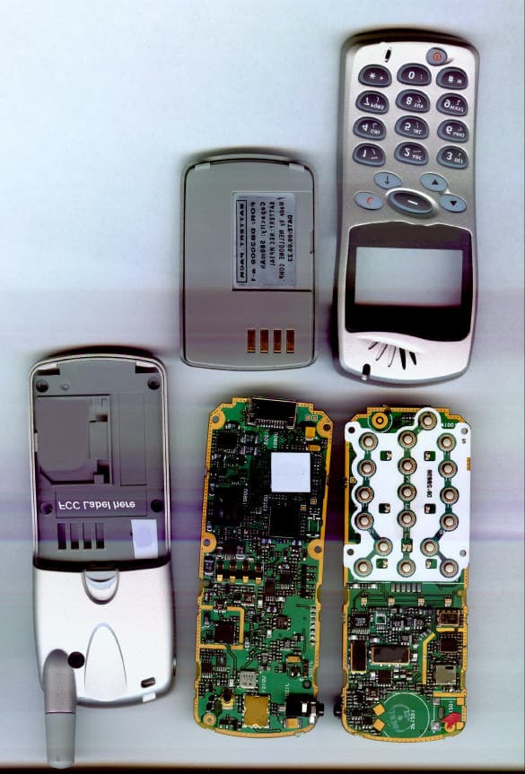
Click to zoom
Application Details
- Equipment Class
- TNE - Licensed Non-Broadcast Transmitter Held to Ear
- Date of Grant
- Jun 06, 2001
- Application Purpose
- Original Equipment
- Date of Application
- Jan 22, 2001
- Equipment Note
- CDMA Handset
- Frequency Range
- 824.04000000 - 848.97000000
- Country
- United States
Documents & Files
Document Text
Text extracted from the exhibit documents filed with the FCC. Open a document above to read the original.
Users Manual
User GuidePhilips Semiconductors – Cellular Americas Extracted from Philips Cellular User Guide, ver 0.1Last Modified: January 25, 2001 Cautions Any changes or modifications to your phone not expressly approved in this document could void your warranty for this equipment and void your warranty to operate this equipment. Only use approved batteries, antennas and chargers. The use of any unauthorized accessories may be dangerous and will invalidate the phone warranty if said accessories cause damage or a defect to the phone. Although your phone is quite sturdy, it is a complex piece of hardware and can be broken. Use common-sense guidelines to avoid dropping, hitting, bending or sitting on it. FCC Notice The phone may cause TV or radio interference if used in close proximity to receiving equipment. The FCC can require you to stop using the telephone if such interference cannot be eliminated. Specifications Subject to Change The information contained in this manual is believed to be correct at the time of printing, however, Philips reserves the right to change or modify any of the specifications without notice or obligation to update existing units. RF Exposure Information This device has been tested for Specific Absorption Rate (SAR) as specified in the FCC document, “Guidelines for Human Exposure to Radio-frequency (RF) Electromagnetic Fields”. This device was found to be compliant with the FCC SAR limits for the following types of operations: • Hands-free operation with ear-piece and microphone • Handheld operation to ear • Hip-mounted operation Use of the phone in other configurations may allow exposure limits to be exceeded and is therefore discouraged. Information to the User This equipment has been tested and found to comply with the limits of a Class B digital device, pursuant to Part 15 of the FCC Rules. These limits are designed to provide reasonable protection against harmful interference in residential installation. This equipment generates, uses and can radiate radio frequency energy and, if not installed and used in accordance with the instructions, may cause harmful interference to radio communications. However, there is no guarantee that interference will not occur in a particular installation; if this equipment does cause harmful interference to radio or television reception, which can be determined by turning the equipment off and on, the user is encouraged to try to correct the interference by one or more of the following measures: • Reorient / relocate the receiving antenna. • Increase the separation between the equipment and receiver. • Connect the equipment into an outlet on a circuit other than that to which the receiver is connected. • Consult the dealer or an experienced radio/TV technician for help. CAUTION: Changes or modifications not expressly approved by the manufacturer responsible for compliance could void user’s authority to operate the equipment.
Users Manual
User GuidePhilips Semiconductors – Cellular Americas Philips Confidential DRAFT COPYLast Modified 03/06/01 Table of Contents 1.1HHP Features______________________________________________________________________4 1.2Power Up – Standby Mode____________________________________________________________5 1.3Menu Structure_____________________________________________________________________6 Standby or Power-On Screen___________________________________________________________8 Main Menu_________________________________________________________________________8 Phone-Book________________________________________________________________________8 Messages__________________________________________________________________________9 History_____________________________________________________________________________9 Settings____________________________________________________________________________9 Network___________________________________________________________________________10 Games____________________________________________________________________________10 Calculator_________________________________________________________________________10 Keypad Lock_______________________________________________________________________10 1.4Menu Tree________________________________________________________________________11 View______________________________________________________________________________12 Search____________________________________________________________________________12 Add Name_________________________________________________________________________12 Delete All__________________________________________________________________________12 Options___________________________________________________________________________12 Speed Dial_________________________________________________________________________12 Clock_____________________________________________________________________________14 Audio_____________________________________________________________________________14 Features__________________________________________________________________________14 1.5System___________________________________________________________________________15 1.6Security__________________________________________________________________________16 1.7FCC Information___________________________________________________________________17 Cautions__________________________________________________________________________17 FCC Notice________________________________________________________________________17 Specifications Subject to Change_______________________________________________________17 FCC Compliance Information__________________________________________________________17 Information to the User_______________________________________________________________17 User GuidePhilips Semiconductors – Cellular Americas Philips Confidential DRAFT COPYLast Modified 03/06/01 The Philips Hand-Held Phone (HHP) is a radio transmitter/receiver that, when turned on, transmits and receives radio frequency (RF) signals. The HPP consists of a display screen and a set of keypads; these are the interfaces to the user, who can make phone calls, edit phone books, or invoke commands to execute a number of specific tasks, including calculator and games. User GuidePhilips Semiconductors – Cellular Americas Philips Confidential DRAFT COPYLast Modified 03/06/01 1.1 HHP Features Display Screen The screen can be divided into three parts: status icon area, text area, and S1/S2 function keys. The group of icons at the top-left screen denotes: • the signal strength • the battery status • the coverage status • H: Home • R: Roaming • the signal status • A: Analog • D: Digital The text area – in the middle – can display up to four lines of text, each having up to 14 characters. Switches S1 and S2 These keys (currently labeled C and ∆) execute the functions that are displayed at the bottom corners of the screen. The functions vary according the level where they are in the menu tree (described later). Arrow Up and Arrow Down These arrow keys (currently labeled ↑and ∇) move the cursor up and down to make a selection of a function or to move the cursor to a different line in a text message. The keys could be also used to move the cursor left, with Arrow-Up key, and right, with Arrow-Down key. Send The Send key is used to make a call. After entering a phone number, the user presses this key to begin dialing the number. End This key has several functions. It can • turn HHP on – by pressing the key; • turn HHP off – by pressing and holding the key for 1 second; • stop execution of an operation – by pressing the key during the execution of an operation; HHP returns to the standby mode. Numeric Keypads These keys allow a user to type alpha-numerical messages, making up the data of which the user may save or broadcast to a receiver. User GuidePhilips Semiconductors – Cellular Americas Philips Confidential DRAFT COPYLast Modified 03/06/01 1.2 Power Up – Standby Mode To power HHP up, the user presses the End key. HHP is turned on to the Power-On or Standby mode, whose initial screen is shown in Figure 1. In this mode, HHP displays the unit status (signal strength, battery, and zone), the current date-time information, and the functions of S1 and S2 keys, which are Menu and Names. The unit status and the S1-S2 functions will be displayed on all subsequent screens. The user makes a phone call by simply dialing a phone number then pressing the Send key. The user can perform other tasks by pressing a series of keys, starting with S1 or S2 key. The tasks initiated from the standby mode can be summarized as follows: • Display this unit phone number q Press End key; the number will be displayed below the line displaying time. • Make a phone call q Dial a number q Press send. • Answer a call q Press any key—except End key. This is possible only when setting-any-key option was enabled. Otherwise (setting-any-key not set) press Send. • End a call q Press End key…
Text truncated - open the document above for the full version.
Block Diagram
Demod Mod BBA or VBA DEMOD MOD TCXO Ant SAW Duplexer IF SAW RF SAW Image RF SAW RF SAW IF SAW LO_Rx PA TX IF AGC TX RF AGC RX IF AGC Isolator Power Detector D0301, U0306 Synthesizer LO Tx Buffer LO Rx Buffer TX Tank RX Tank BBA (Philips) A/D & Filters D/A & Filters Antenna Test Jack J0102 U103 RF2361 FL0101 Atten U0102, Q0101 LNA Atten U0104, Q0102 U0105 RF2466 FL0201 U0201 RF2617 U0101 U0301 FL0302 U0301 FL0301 U0303 RF3105 U0305 Coupler U0304 FL0401 U0402 Q0503 U0501 Q0502 U0502, Q0504 U0801 VCO Q0501 Constant Input Power RX IF AGC Rx: 869 - 894 MHz Tx : 824 - 849 MHz VGA VGA VGA RF Block Diagram RX Section TX Section To Logic Circuit
Cover Letter(s)
Philips Cellular Americas R & D (CARD) Center REQUEST FOR CONFIDENTIALITY Philips CARD Center requests confidentiality with regard to the following documents in the filing for equipment approval identified by FCC ID. No. PD7HHP (1) Schematic diagrams contained in electronic file identified as: schematic_01.pdf schematic_02.pdf schematic_03.pdf schematic_04.pdf schematic_05.pdf schematic_06.pdf schematic_07.pdf schematic_08.pdf schematic_09.pdf schematic_10.pdf schematic_11.pdf schematic_12.pdf It is the opinion of Philips CARD Center disclosure of this information would result in significant loss of revenue. This information should be kept confidential for 10 years. John Kajander RF and System Engineering 2140 Lake Park Blvd. Suite 200 Richardson, Texas 75080 Tel: (972) 705-2465
Cover Letter(s)
Philips Cellular Americas R & D (CARD) Center Federal Communications Commission 7435 Oakland Mills Road Columbia, MD 21046 USA Request for authority to act as Agent to the Federal Communications Commission On Philips CARD Center behalf, I appoint KTL Dallas, Inc. to act as agent in the preparation of this application for equipment authorization to the Federal Communications Commission. I certify that submitted Exhibits properly describe the device or system for which equipment authorization is sought. I also certify that each unit manufactured, imported or marketed, as defined in the Commission's regulations will have affixed to it a label identical to that submitted for approval with this application. John Kajander RF and System Engineering 2140 Lake Park Blvd. Suite 200 Richardson, Texas 75080 Tel: (972) 705-2465
ID Label/Location Info
FCC ID. PD7HHP Vinyl label printed with permanent ink. Text 8 pt. Arial
Operational Description
1Description of Equipment Under Test (EUT) The EUT is a CDMA single-mode Hand Held Phone (HHP), designed to meet or exceed the TIA/EIA IS-95B Standard. The EUT is capable of operating The technical description included in this section covers the receive (RX) and the transmit (TX) sections and the logic hardware and Baseband section of the HHP. The technical descriptions are intended to describe supporting hardware circuits only and are not intended to address firmware or protocol issue except where applicable. 1.1. Description of Circuits and Devices 1.2. RF Receive Path Description The receive RF section is designed to receive CDMA signals in the 869 – 894 MHz frequency band. The input RF section consist of a Rx/Tx SAW duplexer (U0101), an antenna input switch (J0102), a fixed attenuator (U0102), and the Low Noise Amplifier (LNA), U0103. The antenna switch functions as an external test input/output port to test the HHP. The Rx section of the duplexer provides bandpass filtering of unwanted out-of- band signals prior to being applied to the LNA input. The RF input attenuator is switched into the receive path providing –10 dB attenuation at approximately –95 dBm. This provides overdrive protection and reduces IMD within the RF front end. The LNA is the first gain block in the receive chain and essentially establishes the receiver RF section input noise figure. The RF SAW filter (FL0101), provides image rejection filtering for the RF front-end. The image is located at a frequency which is twice the first IF frequency above the Local Oscillator (LO) frequency. The RF attenuator following the LNA switches –10 dB into the circuit when the input signal is at approximately –85 dBm. This provides at reduction in the signal level to the first mixer that functions to reduce overload, IMD and spurious responses. The first mixer (U0106) is an active-mixer that provides positive conversion gain and frequency translation by down- converting the incoming RF spectrum to the first intermediate frequency (IF). The Local Oscillator (LO) drive level has been set to provide optimum IMD performance. The differential output is coupled into an IF SAW filter that provides receive selectivity for the IF chain. The differential Controlled Crystal Oscillator (TCXO), U0702, provides the input reference frequency to the synthesizer. The synthesizer output provide the local oscillator input for the receive chain (for down-conversion) via buffer (Q0502). 1.4. TX Synthesizer Section Description The Synthesizer is shared by both transmit and the receive chains. The synthesizer output also provides the local oscillator (for up-conversion) to the transmit chain via buffer (Q0503). 1.5. Transmitter (TX) Section Description The transmitter section receives it input from the BBA chip (U0801). The signal is received by the variable voltage amplifier (VGA), U0402. The function of the VGA is to ultimately establish the RF output level at the RF antenna input terminals. The VGA receives an input control voltage from the BBA, which sets the VGA’s gain/attenuation response according to the received signal strength. The VGA differential output is routed to the input of a SAW filter (FL0401), that establishes transmit IF selectivity. The filter output is up-converted to the final transmit frequency by mixer (U0301) which is 45 MHz’s below the incoming CDMA received signal. Further filtering is provided by RF SAW filter (FL0301) before the signal is applied to a second VGA (U0302). The two VGA’s in the transmit chain collectively work to provide the combined dynamic range required to for the maximum/minimum output power ratio. The power amplifier (PA), U0303, further provides signal amplification in the transmit chain. The PA can be rendered inactive by switch (Q0301). The PA is a linear power amplifier. The output is routed through the directional coupler (U0304) where a sample is data and detected by diodes (UD0301) and amplified by op amp (U0306). A circulator (U0305), is provided to buffer or isolated the PA output from reflective energy from the antenna circuit. The PA output is finally routed to the Tx section of duplexer (U0101) which functions to band limited the transmit signal prior to entering the antenna input terminals. The duplexer further functions to isolated the CDMA receive band from the CDMA transmit band by approximately 53 dB. The transmitter signal arrives at the duplexer input terminal where antenna test jack (J0102), provides the functionality of a test port for testing and monitoring the HHP performance. The transmit signal finally arrives at the The BBA chip (U0701) and the CDMA+100 (U0801) chips together comprise the baseband analog and DSP sections for the HHP. In the BBA chip, all data conversions, such as the analog to digital (ADC) and the digital to analog (DAC), are provided. In the CDMA+100 chip all digital signal processing (DSP) functionality is provided. Both chips are Philips proprietary chip designs. They also function as the baseband Modem providing the modulation and demodulation for the CDMA receive and transmit signals. 1.7. LCD readout Description The LCD is 87 x 65 pixels. The Display will illustrated the status of the phone, including battery status, channel number (in test mode), signal strength, menu’s roaming or home. Etc. 1.8. CPU Section Description The CPU is used to provide timing and commands to the RF section and the hardware section. The CPU firmware is stored in FLASH non-volatile memory. The firmware can be upgraded from the bottom connector over a standard RS-232 interface. A volatile SRAM memory is used to store temporary data. 1.9. Serial Buss Interface Description The interface connector (J1203), is located on the bottom of the HHP where commands, data and external power may be applied to the HHP. The data interface is RS-232. 1.10. Function of Active Devices The active devices used in the HHP are listed in Table 1. Table 1 Active HHP Parts Philips P/NQTYRef. DesignatorPart…
Text truncated - open the document above for the full version.
Parts List/Tune Up Info
Tuneup Procedure FCC ID. PD7HHP The Power amplifier is set at the factory via firmware table. During use the power output is adjusted in a closed-loop configuration via link management protocol. There is no manual tuning of the EUT frequency or power.
RF Exposure Info
CELLTECH RESEARCH INC. Test Report S/N: 121500-47PD7 1955 Moss Court, Kelowna, Dates of Tests: December 20 & 29, 2000 B.C. CANADA V1Y 9L3 _________________________________________________________________________________________________________ © 2000 Celltech Research Inc. CERTIFICATE OF COMPLIANCE SAR EVALUATION This wireless mobile and/or portable device has been shown to be compliant for localized Specific Absorption Rate (SAR) for uncontrolled environment/general exposure limits specified in ANSI/IEEE Std. C95.1-1992 and had been tested in accordance with the measurement procedures specified in ANSI/IEEE Std. C95.3-1999. (See test report). I attest to the accuracy of data. All measurements were performed by me or were made under my supervision and are correct to the best of my knowledge and belief. I assume full responsibility for the completeness of these measurements and vouch for the qualifications of all persons taking them. Celltech Research Inc. certifies that no party to this application has been denied FCC benefits pursuant to Section 5301 of the Anti-Drug Abuse Act of 1988, 21 U.S.C. 853(a). Shawn McMillen General Manager Celltech Research Inc. Test Lab: CELLTECH RESEARCH INC. Testing and Engineering Lab 1955 Moss Court Kelowna, B.C. Canada V1Y 9L3 Phone: 250 - 860-3130 Fax: 250 - 860-3110 Toll Free: 1-877-545-6287 e-mail: [email protected] web site: www.globuswireless.com Applicant Name: PHILIPS SEMICONDUCTOR 2140 Lake Park Blvd. Richardson, TX 75080 Attn: John Kajander Tel.: 972-705-2465 FCC ID: PD7HHP Model(s): HHPV1.0 Equipment Type: Single-Mode CDMA Cellular Phone Classification: Licensed Non-Broadcast Transmitter Held to Ear (TNE) Tx Frequency Range: 824.70 - 848.31 MHz Rx Frequency Range: 869.70 - 893.31 MHz Max. RF Output Power: 22.9 dBm (Conducted) FCC Rule Part(s): 2.1093; ET Docket 96.326 CELLTECH RESEARCH INC. Test Report S/N: 121500-47PD7 1955 Moss Court, Kelowna, Dates of Tests: December 20 & 29, 2000 B.C. CANADA V1Y 9L3 _________________________________________________________________________________________________________ © 2000 Celltech Research Inc. TABLE OF CONTENTS 1.0 INTRODUCTION.................................................................. 1 2.0 DESCRIPTION OF EUT.......................................................... 1 3.0 SAR MEASUREMENT SYSTEM ............................................. 2 4.0 MEASUREMENT SUMMARY.................................................. 3 5.0 SAR LIMITS........................................................................ 3 6.0 DETAILS OF SAR EVALUATION........................................... 4 7.0 EVALUATION PROCEDURES................................................. 5 8.0 SYSTEM VALIDATION.......................................................... 5 9.0 SIMULATED EQUIVALENT TISSUES...................................... 6 10.0 TISSUE PARAMETERS......................................................... 6 11.0 SYSTEM SPECIFICATIONS.................................................... 7 12.0 TEST EQUIPMENT LIST........................................................ 8 13.0 MEASUREMENT UNCERTAINTIES........................................ 9 14.0 REFERENCES...................................................................... 10 APPENDIX A - SAR MEASUREMENT DATA........................................ 11 APPENDIX B - DIPOLE VALIDATION................................................ 12 APPENDIX C - PROBE CALIBRATION............................................... 13 APPENDIX D - SAR TEST SETUP PHOTOGRAPHS.............................. 14 CELLTECH RESEARCH INC. Test Report S/N: 121500-47PD7 1955 Moss Court, Kelowna, Dates of Tests: December 20 & 29, 2000 B.C. CANADA V1Y 9L3 _________________________________________________________________________________________________________ © 2000 Celltech Research Inc. Philips Semiconductor FCC ID: PD7HHP 1 Single-Mode CDMA Cellular Phone (824-849MHz) 1.0 INTRODUCTION This measurement report shows compliance of the Philips Semiconductor Model: HHPV1.0 Single-Mode 800MHz CDMA Cellular Phone FCC ID: PD7HHP with FCC Part 2.1093, ET Docket 96-326 Rules for mobile and portable devices. The test procedures, as described in American National Standards Institute C95.1-1992 (1), FCC OET Bulletin 65-1997 were employed. A description of the product and operating configuration, detailed summary of the test results, methodology and procedures used in the evaluation, equipment used, and the various provisions of the rules are included within this test report. 2.0 DESCRIPTION of Equipment Under Test (EUT) EUT Type Single-Mode CDMA Cellular Phone FCC ID PD7HHP Equipment Class Licensed Non-Broadcast Transmitter Held to Ear (TNE) Model No.(s) HHPV1.0 FCC Rule Part(s) § 2.1093, Docket 96-326 Application Type Certification Tx Frequency Range (MHz) 824.70 - 848.31 S/N No. Pre-production Rx Frequency Range (MHz) 869.70 - 893.31 Max. RF Output Power Tested 22.9 dBm (Conducted) Modulation CDMA Battery Type(s) NEC MP5AL 580mAh Antenna Type Stubby Antenna Length 22.8 mm CELLTECH RESEARCH INC. Test Report S/N: 121500-47PD7 1955 Moss Court, Kelowna, Dates of Tests: December 20 & 29, 2000 B.C. CANADA V1Y 9L3 _________________________________________________________________________________________________________ © 2000 Celltech Research Inc. Philips Semiconductor FCC ID: PD7HHP 2 Single-Mode CDMA Cellular Phone (824-849MHz) 3.0 SAR MEASUREMENT SYSTEM Celltech Research SAR measurement facility utilizes the Dosimetric Assessment System (DASY™) manufactured by Schmid & Partner Engineering AG (SPEAG™) of Zurich, Switzerland. The DASY system is comprised of the robot controller, computer, near-field probe, probe alignment sensor, and the generic twin phantom containing brain or muscle equivalent material (see Figure 6). The robot is a six-axis industrial robot performing precise movements to position the probe to the location (points) of maximum electromagnetic field (EMF). A cell controller system contai…
Text truncated - open the document above for the full version.
Test Report
KTL Test Report:0L0459RUS1 Applicant:Philips Semiconductor 2140 Lake Park Blvd., #200 Richardson, TX 75080 Equipment Under Test:CDMA Mobile Handset (E.U.T.) FCC ID:PD7HHP In Accordance With:FCC Part 22, Subpart H 800 MHz Cellular Subscriber Units Tested By:KTL Dallas Inc. 802 N. Kealy Lewisville, TX 75057-3136 Authorized By: Tom Tidwell, RF Group Manager Date:December, 2000 Total Number of Pages:39 KTL Dallas FCC PART 22, SUBPART H 800 MHz CELLULAR SUBSCRIBER UNITS EQUIPMENT: CDMA Mobile Handset FCC ID: PD7HHPPROJECT NO.: 0L0459RUS1 Page 2 of 39 Table of Contents Section 1. Summary of Test Results........................................................................................3 Section 2. General Equipment Specification.............................................................................5 Section 3. RF Power Output....................................................................................................8 Section 4. Occupied Bandwidth...............................................................................................9 Section 5. Spurious Emissions at Antenna Terminals.............................................................12 Section 6. Field Strength of Spurious.....................................................................................20 Section 7. Frequency Stability...............................................................................................23 Section 8. Test Equipment List..............................................................................................25 ANNEX A - Test Details..........................................................................................................26 ANNEX B - Test Diagrams.......................................................................................................36 KTL Dallas FCC PART 22, SUBPART H 800 MHz CELLULAR SUBSCRIBER UNITS EQUIPMENT: CDMA Mobile Handset FCC ID: PD7HHPPROJECT NO.: 0L0459RUS1 Page 3 of 39 Section 1.Summary of Test Results Manufacturer:Philips Semi Conductor Model No.:CDMA Mobile Handset Serial No.:16 General:All measurements are traceable to national standards. These tests were conducted on a sample of the equipment for the purpose of demonstrating compliance with FCC Part 22, Subpart H. New SubmissionProduction Unit Class II Permissive ChangePre-Production Unit THIS TEST REPORT RELATES ONLY TO THE ITEM(S) TESTED. THE FOLLOWING DEVIATIONS FROM, ADDITIONS TO, OR EXCLUSIONS FROM THE TEST SPECIFICATIONS HAVE BEEN MADE. See “ Summary of Test Data”. NVLAP LAB CODE: 100426-0 KTL Dallas Inc. authorizes the above named company to reproduce this report provided it is reproduced in its entirety and for use by the company’s employees only. Any use which a third party makes of this report, or any reliance on or decisions to be made based on it, are the responsibility of such third parties. KTL Dallas Inc. accepts no responsibility for damages, if any, suffered by any third party as a result of decisions made or actions based on this report. This report applies only to the items tested. KTL Dallas FCC PART 22, SUBPART H 800 MHz CELLULAR SUBSCRIBER UNITS EQUIPMENT: CDMA Mobile Handset FCC ID: PD7HHPPROJECT NO.: 0L0459RUS1 Page 4 of 39 Summary Of Test Data NAME OF TEST PARA. NO. SPEC.MEAS.RESULT RF Power Output2.10467W ERP+23 dBmComplies Audio Frequency Response2.10476dB/OctaveNANA Audio Low Pass Filter Response2.1047GraphNANA Modulation Limiting2.1047GraphNANA Occupied Bandwidth (Voice & SAT)2.1049MaskNANA Occupies Bandwidth (WB Data & SAT)2.1049MaskNANA Occupied Bandwidth (ST)2.1049MaskNANA Occupied Bandwidth (SAT)2.1049MaskNANA Occupied Bandwidth (CDMA)2.1049Not SpecifiedIS-95BComplies Spurious Emissions at Antenna Terminals 2.1051-13 dBmPASSComplies Field Strength of Spurious Emissions2.1053 82.3 dBμV/m59 dBμV/m Complies Frequency Stability2.10552.5 ppmComplies Footnotes: . KTL Dallas FCC PART 22, SUBPART H 800 MHz CELLULAR SUBSCRIBER UNITS EQUIPMENT: CDMA Mobile Handset FCC ID: PD7HHPPROJECT NO.: 0L0459RUS1 Page 5 of 39 Section 2.General Equipment Specification Frequency Range: 824 - 849 MHz TX 869 - 894 MHz RX Necessary Bandwidth: 1.25 MHz Type of Modulation and Designator: 1M25F9W, IS-95B CDMA Output Impedance: 50 ohms RF Power Output (rated): +23 dBm Duty Cycle: Continuous Channel Spacing: 1.25 MHz Operator Selection of Frequency: Software Controlled Power Output Adjustment Capability: Software Controlled KTL Dallas FCC PART 22, SUBPART H 800 MHz CELLULAR SUBSCRIBER UNITS EQUIPMENT: CDMA Mobile Handset FCC ID: PD7HHPPROJECT NO.: 0L0459RUS1 Page 6 of 39 Modifications Made During Testing During the testing modification to the EUT include grounding the LCD display corners to the ground plan of the main pcb of the unit. KTL Dallas FCC PART 22, SUBPART H 800 MHz CELLULAR SUBSCRIBER UNITS EQUIPMENT: CDMA Mobile Handset FCC ID: PD7HHPPROJECT NO.: 0L0459RUS1 Page 7 of 39 Operational Description The EUT is a CDMA single-mode Hand Held Phone (HHP) that operates in the AMPS band. The phone is completely compatible with the IS-95B standard. System Diagram 3.8 vdc Battery LCD Display KTL Dallas FCC PART 22, SUBPART H 800 MHz CELLULAR SUBSCRIBER UNITS EQUIPMENT: CDMA Mobile Handset FCC ID: PD7HHPPROJECT NO.: 0L0459RUS1 Page 8 of 39 Section 3.RF Power Output NAME OF TEST: RF Power OutputPARA. NO.: 2.1046 TESTED BY: Kevin RoseDATE: Dec 8 2000 Test Results:Complies. Measurement Data: Output Power (dBm) Rated Power (dBm) Measured / Rated (dBm) +24.57+23.01.87 Equipment Used: 1464 791 1484 1485 1480 Measurement Uncertainty: +/- 1.1dB Temperature: 21°C Relative Humidity: 46% KTL Dallas FCC PART 22, SUBPART H 800 MHz CELLULAR SUBSCRIBER UNITS EQUIPMENT: CDMA Mobile Handset FCC ID: PD7HHPPROJECT NO.: 0L0459RUS1 Page 9 of 39 Section 4.Occupied Bandwidth NAME OF TEST: Occupied BandwidthPARA. NO.: 2.1047 (Digital Modulation) TESTED BY: Kevin RoseDATE: Dec 7 2000 Test Results:Complies. Measurement Data: See attached graph. Equipment Used: 1036 1426 CUSTOMER INTERCONNECT…
Text truncated - open the document above for the full version.
Test Report
Dallas Headquarters: 802 N. Kealy Lewisville, TX 75057 Tel: (972) 436-9600 Fax: (972) 436-2667 KTL Dallas, Inc. Field Strength of Spurious Emissions Page 1 of1 CompleteX Job No.:0L0459RDate:12/7/00Preliminary Specification:Field Strength of SpuriousTemperature(°C):21 Tested By:Kevin RoseRelative Humidity(%)46 E.U.T.:CDMA Handheld Phone Configuration:Transmit full power Sample Number:1 Location:AC 3RBW:1 MHzMeasurement Detector Type:PeakVBW:1 MHz Distance: 3m Test Equipment Used Antenna…
Text truncated - open the document above for the full version.
Contact Information
Applicant
John Kajander(RF and System Engineer)
[email protected]972-705-2465
Technical Contact
KTL Dallas, Inc.Tom Tidwell
[email protected]972-436-9600
802 N. Kealy · Lewisville, Texas · United States
Non-Technical Contact
KTL Dallas, Inc.Alma Torres
[email protected]972-436-9600
Test Firm
Nemko Dallas, Inc.Michael Cantwell
Technical Specifications
| # | Rule Parts | Frequency Range | Power Output | Emission | Tolerance |
|---|---|---|---|---|---|
| 1 | 22.901(d) | 824.04 MHz - 848.97 MHz | 133.00 mW | 1M25F9W | 100.0000000000 Hz |