PDT-SK3732-T720Tablet PC
SK Mtek microeletronics (shenzhen) limited.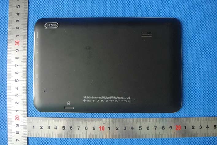
Click to zoom
Application Details
- Equipment Class
- DSS - Part 15 Spread Spectrum Transmitter
- Date of Grant
- Sep 25, 2012
- Application Purpose
- Original Equipment
- Date of Application
- Sep 25, 2012
- Equipment Note
- Tablet PC
- Frequency Range
- 2402.00000000 - 2480.00000000
- Country
- China
Documents & Files
Document Text
Text extracted from the exhibit documents filed with the FCC. Open a document above to read the original.
Users Manual
Clear T720 Quick Start Guide Thank you for purchasing Clear T720. This device will provide you with high quality mobile entertainment and communication. Before you start, familiarize yourself with the icons you will see in this guide. Warning – situations that could cause injury to yourself or others, damage to your device or other equipment. Note – notes, usage tips, or additional information for using your device. Copyright Copyright ©2012 Wintec Industries. This guide is protected under international copyright laws. No part of this guide may be used in any form without the permission of Wintec Industries. Trademarks Clear logo is registered trademark of Wintec Industries. The Android logo, Google™ are the trademark of Google, Inc. Bluetooth is a registered trademark of the Bluetooth SIG, Inc. worldwide. Windows Media Player is a registered trademark of the Microsoft Corporation. Wi-Fi and the Wi-Fi logo are registered trademarks of the Wi-Fi Alliance. All other trademarks and copyrights are the property of their respective owners. Device Layout Front View Item Description 1 Front Camera 2 LCD & Touch Screen 3 Power key 4 Headset jack 5 Micro USB jack 6 HDMI jack 7 DC jack 8 Volume key Rear View Item Description 1 Speaker 2 microSD Slot 3 Rear Camera Getting started Turn your device on and off To turn on your device, press and hold the Power key. If you turn on your device for the first time, some on screen instructions will be displayed. You need to follow the instructions to set up your device. You have to sign in Google or create a Google account to use the applications that need to interact with Google Server. To turn off your device, press and hold the Power key and select Power off and then OK. Using Applications Notification Panel Tap the right bottom bar to open notification panel. You can expand the opened notification panel by tap it, and then can shrink by tap it again or other area of screen. Volume control You can adjust the volume of device by a couple of methods. One is by volume key on side of your device. The other is by tap the volume down or volume up icon in bottom bar of LCD. Charging the battery Before using this device for the first time, you must charge the battery. Use only Wintec Industries approved charger for this device and cables. Unapproved charger or cable can cause batteries to explode or damage this device. If the battery is completely discharged, you can’t turn on the device even with the charger connected. Allow a depleted battery to charge for a few minutes before you try to turn on the device. Connect the charger to an electrical socket and plug the charger cable into the DC jack of your device . Connecting the charger cable into the DC jack of your device improperly can cause serious damage to your device or charger. Any damage caused by misuse is not covered by the warranty. When the battery is fully charged, unplug the charger cable from your device first, and then unplug the charger from the electrical socket. Safety Information To prevent injury to yourself and others or damage to this device, read all of the following information before using this device. Prevent electric shock and explosion. Do not use unauthorized or damaged power cords or plugs, or loose electrical sockets. Do not touch the power cord with wet hands, or disconnect the charger by pulling on it. Do not damage or bend the power cord. Do not use this device while charging or touch device with wet hands. Do not drop or impact to the charger or the device. Do not use the device during thunderstorm. Do not short-circuit the charger. Handle of the device and chargers with care Use only manufacturer approved charger designed for the device. Unapproved charger can cause serious damage to the device. Never dispose of the device in a fire. Never place the device on or in heating devices, such as stoves, microwave ovens, radiators. The device may damage when overheated. Never place the device on the dashboard in a car without any care. If it is exposed to the sun light for a long time, the inside temperature of the car may damage the device. Do not use the device near any other electronic devices. Most electronic devices use radio frequency signals, the device may interfere with other electronic devices. Do not use the device in a hospital or near medical equipment including pacemaker that can be interfered with by radio frequency. Do not use the device in a place that is not allowed. FCC STATEMENT 1. This device complies with Part 15 of the FCC Rules. Operation is subject to the following two conditions: (1) This device may not cause harmful interference. (2) This device must accept any interference received, including interference that may cause undesired operation. 2. Changes or modifications not expressly approved by the party responsible for compliance could void the user's authority to operate the equipment. NOTE: This equipment has been tested and found to comply with the limits for a Class B digital device, pursuant to Part 15 of the FCC Rules. These limits are designed to provide reasonable protection against harmful interference in a residential installation. This equipment generates uses and can radiate radio frequency energy and, if not installed and used in accordance with the instructions, may cause harmful interference to radio communications. However, there is no guarantee that interference will not occur in a particular installation. If this equipment does cause harmful interference to radio or television reception, which can be determined by turning the equipment off and on, the user is encouraged to try to correct the interference by one or more of the following measures: Reorient or relocate the receiving antenna. Increase the separation between the equipment and receiver. Connect the equipment into an outlet on a circuit different from that to which the receiver is connected. Consult the dealer or an experienced radio/TV technician for help.
External Photos
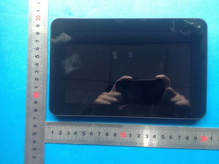
SK Mtek microeletronics (shenzhen) limited.Model:T720 APPENDIX B - EUT PHOTOGRAPHS EUT - Rear View 1 EUT - Rear View 2 SK Mtek microeletronics (shenzhen) limited.Model:T720 EUT - Rear View 3 EUT - Rear View 4 SK Mtek microeletronics (shenzhen) limited.Model:T720 EUT - Rear View 5 EUT - Rear View 6
ID Label/Location Info
SK Mtek microeletronics (shenzhen) limited.Model:T720 Proposed Label Location on EUT FCC ID Label Location
ID Label/Location Info
SK Mtek microeletronics (shenzhen) limited.Model:T720 APPENDIX A - PRODUCT LABELING Proposed FCC ID Label Format Label size: 60mm*40mm 60mm 40mm Company:SK Mtek microeletronics (shenzhen) limited. Name:Tablet PC Model Number: T720 FCC ID: PDT-SK3732-T720 This device complies with Part 15 of the FCC Rules. Operation is subject to the following two conditions: (1) This device may not cause harmful interference, and (2) This device must accept any interference received, including interference that may cause undesired operation.
Internal Photos
SK Mtek microeletronics (shenzhen) limited. Model: T720 APPENDIX C - EUT INTERNAL PHOTOGRAPHS EUT – Open View 1 EUT – Open View 2(Remove copper foil) SK Mtek microeletronics (shenzhen) limited. Model: T720 EUT – PCB View 1 EUT – PCB View 2 SK Mtek microeletronics (shenzhen) limited. Model: T720 EUT – PCB View 3 EUT – Battery View 1 SK Mtek microeletronics (shenzhen) limited. Model: T720 EUT – Battery View 2
Test Report
Report No.:MTI120910002RF-2 Page 1 of 47 FCC Part 15C Measurement And Test Report For SK Mtek microeletronics (shenzhen) limited. 12/F, Microprofit B.D. South 6 Road, High-Tech Industrial Park, Nanshan District, Shenzhen, China FCC ID: PDT-SK3732-T720 September 17, 2012 T h i s Re p o r t Co n c e r n s : O r ig in a l Re p o r t Eq u i p m e n t T yp e : T a b le t P C Report Number: MT I 1 2 0 9 1 0 0 0 2RF-2 Test Engineer: Reviewed By: Approved & Authorized By: Test Date: September 10- September 16,2012 Prepared By: MTI Technology Laboratory Ltd. 10F, Yinxing Business Hotel, Xixiang Road, Bao’an District, Shenzhen, P,R.China. Tel: +86-755-8885 0135 Fax: +86-755-8885 0136 Note: This test report is limited to the above client company and the product model only. It may not be duplicated without prior written consent of MTI Technology Laboratory Ltd. Report No.:MTI120910002RF-2 Page 2 of 47 TABLE OF CONTENTS 1. GENERAL INFORMATION ......................................................................................................................... 4 1.1 PRODUCT DESCRIPTION FOR EQUIPMENT UNDER TEST (EUT) ....................................................................................... 4 1.2 RELATED SUBMITTAL(S) / GRANT (S) ............................................................................................................................ 4 1.3 TEST METHODOLOGY ................................................................................................................................................. 5 1.4 TEST FACILITY ........................................................................................................................................................... 5 2. SYSTEM TEST CONFIGURATION ............................................................................................................ 6 2.1 EUT CONFIGURATION ................................................................................................................................................ 6 2.2 EUT EXERCISE .......................................................................................................................................................... 6 2.3 GENERAL TEST PROCEDURES ..................................................................................................................................... 6 2.4 LIST OF MEASURING EQUIPMENTS USED ...................................................................................................................... 7 2.5 TEST CONDUCTION ..................................................................................................................................................... 8 2.6 TEST PERIPHERAL INFORMATION ................................................................................................................................. 8 3. SUMMARY OF TEST RESULTS ................................................................................................................ 9 4. ANTENNA REQUIREMENT ..................................................................................................................... 10 4.1 STANDARD APPLICABLE ............................................................................................................................................ 10 4.2 ANTENNA CONNECTED CONSTRUCTION ...................................................................................................................... 10 5. CONDUCTED DISTURBANCES .............................................................................................................. 11 5.1. MEASUREMENT UNCERTAINTY .................................................................................................................................. 11 5.2. LIMIT OF CONDUCTED DISTURBANCES (CLASS B) ....................................................................................................... 11 5.3. EUT SETUP ........................................................................................................................................................... 11 5.4. INSTRUMENT SETUP ................................................................................................................................................ 11 5.5. TEST PROCEDURE .................................................................................................................................................. 12 5.6. SUMMARY OF TEST RESULTS ................................................................................................................................... 12 5.7. TEST RESULT ......................................................................................................................................................... 12 6. NUMBER OF HOPPING CHANNELS AND CHANNEL SPACING ......................................................... 15 6.1 STANDARD APPLICABLE ............................................................................................................................................ 15 6.2 EUT SETUP ............................................................................................................................................................ 15 6.3 TEST EQUIPMENT LIST AND DETAILS .......................................................................................................................... 15 6.4 TEST PROCEDURE ................................................................................................................................................... 15 6.5 TEST RESULT .......................................................................................................................................................... 15 7. DWELL TIME OF A HOPPING CHANNEL .............................................................................................. 19 7.1 LIMITS OF DWELL TIME MEASUREMENT .......................................................................................…
Text truncated - open the document above for the full version.
Test Setup Photos
SK Mtek microeletronics (shenzhen) limited. Model: T720 APPENDIX D - TEST SETUP PHOTOGRAPHS Radiation Emission Test Setup (Below 1G): Radiation Emission Test Setup (Above 1G) SK Mtek microeletronics (shenzhen) limited. Model: T720 Conducted Emission Test Setup
Contact Information
Applicant
Amy Jiang(sales)
Test Firm
Shenzhen NTEK Testing Technology Co., Ltd.Jason Chen
Technical Specifications
| # | Rule Parts | Frequency Range | Power Output |
|---|---|---|---|
| 1 | 15C | 2.40 GHz - 2.48 GHz | 700.00 µW |
Other Applications from SK Mtek microeletronics (shenzhen) limited.
PDT-ST7421-T750
Dec 02, 2013Tablet
Equipment Class
DTS - Digital Transmission System
PDT-ST7222-T730
Nov 24, 2013Tablet
Equipment Class
DTS - Digital Transmission System
PDT-SK8241-8320
Sep 16, 2013Tablet
Equipment Class
DSS - Part 15 Spread Spectrum Transmitter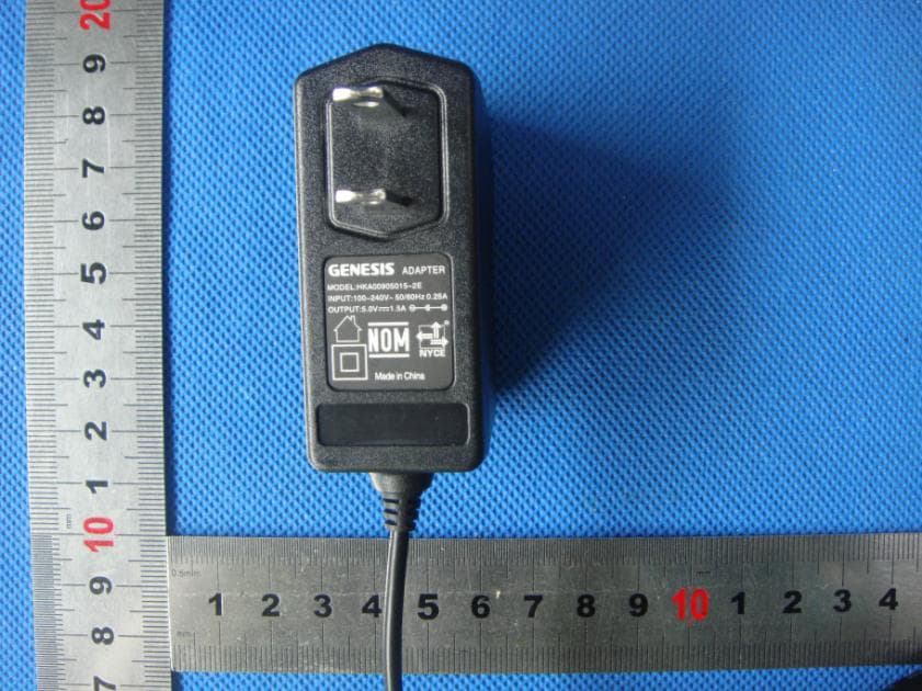
PDT-SK7241-7305
Sep 12, 2013Tablet
Equipment Class
DTS - Digital Transmission System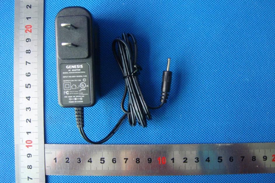
PDT-SK3841-8220S
Feb 04, 2013Tablet
Equipment Class
DTS - Digital Transmission System