PDXAQUA-R2000Pool Leveler Transmitter
Sons Design & Manufacturing, Inc.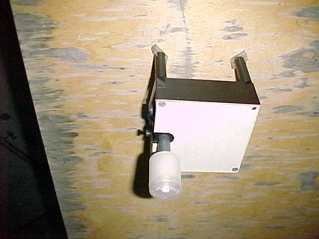
Click to zoom
Application Details
- Equipment Class
- DSC - Part 15 Security/Remote Control Transmitter
- Date of Grant
- Apr 19, 2001
- Application Purpose
- Original Equipment
- Date of Application
- Apr 19, 2001
- Equipment Note
- Pool Leveler Transmitter
- Frequency Range
- 418.00000000 - 418.00000000
- Country
- United States
Documents & Files
Document Text
Text extracted from the exhibit documents filed with the FCC. Open a document above to read the original.
Users Manual
SDMI April 2001 “AQUARISER” Installation and Operation Manual Swimming Pool Water Level Maintenance System Manufactured By SDMI Dallas, Texas IMPORTANT INFORMATION TO THE USER. To the users of this manual and electronic equipment: FCC ID: PDXAQUA-R2000. This device complies with part 15 of the FCC Rules. Operation is subject to the following two conditions: 1. This device may not cause harmful interference, and 2. This device must accept any interference received, including interference that may cause undesired operation. Additionally, changes or modifications made to the unit not expressly approved by the manufacturer for compliance to the FCC Rules, could void the user’s authority to operate the equipment. What this means is the equipment, as delivered from the factory, meets all FCC requirements and regulations. This allows the purchaser to operate the system without a special license from the FCC (Federal Communication Commission). If modifications are made to the radio system that altered its emissions or power output, the equipment may no longer meet the FCC Rules, and the person operating the equipment may be in violation of the law. IMPORTANT Dear Customer: Thank you for your purchase of a SDMI product. Completing this Product Registration Card is an important first step in your new ownership. Here are three reasons for registering now: • WARRANTY SERVICE Filling out this card will help you obtain more efficient warranty service, and its return confirms that you have read and understood your warranty. • PROTECT YOUR PRODUCT By returning this registration, we can confirm your purchase in case of theft or other loss. • FOR YOUR SAFETY Filling out the attached card is our only method of ensuring that we can contact you in the event of any product issues that may arise. P RODUCT R EGISTRATION Date of Purchase:___________________ Type of Equipment:__________________ Your Name and Address: ___________________________________ Serial No. __________________________ Model No. _________________________ Dealer’s Name and Address: ___________________________________ P RODUCT R EGISTRATION RETURN IMMEDIATELY IMPORTANT PRODUCT REGISTRATION SDMI PO BOX 29175 DALLAS, TX 75229 SDMI PO BOX 29175 DALLAS, TX 75229 WARRANTY SDMI garrantys the components of the “Aquariser” water level maintenance system to be free of defects in materials and workmanship for one year from the date of purchase. SDMI SHALL NOT BE LIABLE FOR INCIDENTAL OR CONSEQUENTIAL DAMAGES. ITS SOLE LIABILITY SHALL BE LIMITED TO REPAIR AND/OR REPLACEMENT. THIS WARRANTY IS EXCLUSIVE AND IS IN LIEU OF ALL OTHER WARRANTIES EXPRESSED OR IMPLIED. WARRANTY CLAIMS WITHIN THE FIRST YEAR OF OWNERSHIP PERTAINING TO THE BATTERIES SHALL BE HANDLED ON AN EXCHANGE BASIS. MODIFICATIONS TO THE SYSTEM NOT AUTHORIZED AND/OR APPROVED BY SDMI SHALL VOID THIS WARRANTY. RECIEVER SOLENOID VALVE ASSEMBLY TRANSMITTER AND FLOAT ASSEMBLY Figure 1. “AQUARISER” Water Level Maintenance System SDMI 1-1 TABLE OF CONTENTS SECTION PAGE Section 1. General Information Description ....................................................................................................................... 1-1 How It Works ....................................................................................................................1-1 Specifications ................................................................................................................... 1-1 Section 2. Installation Introduction....................................................................................................................... 2-1 Tools and Materials Required for Installation ................................................................... 2-1 Pre-Installation Checks .................................................................................................... 2-1 Communication Test ........................................................................................................ 2-3 Installing the Transmitter .................................................................................................. 2-4 Installing the Receiver ...................................................................................................... 2-5 Installing the Solenoid Valve Assembly ............................................................................ 2-5 Section 3. Operation General ............................................................................................................................ 3-1 Preparing the System for Operation ................................................................................. 3-2 Setting Float Level............................................................................................................3-2 Setting Receiver Address Code Switches ........................................................................ 3-4 Winterizing System........................................................................................................... 3-4 Returning System to Operation ........................................................................................ 3-5 Section 4. Maintenance and Troubleshooting Maintenance.....................................................................................................................4-1 Troubleshooting................................................................................................................4-1 Section 5. Spare Parts List Solenoid Valve Assembly ................................................................................................. 5-1 Receiver Assembly........................................................................................................... 5-2 Transmitter Assembly....................................................................................................... 5-3 SDMI 1-1 Section 1 - GENERAL INFORMATION DESCRIPTION. The AQUARISER pool level maintenance system consists of the three major component assembli…
Text truncated - open the document above for the full version.
Cover Letter(s)
SONS Design and Manufacturing, Inc. P.O. Box 29175 Dallas, Texas 75229 December 15, 2000 Federal Communications Commission 7435 Oakland Mills Road Columbia, MD 21046 To Whom It May Concern: This is a letter of authorization to accept our appointment of MET Laboratories, Inc. as Agent for Sons Design and Manufacturing, Inc., P.O. Box 29175, Dallas, Texas 75229, to sign applications before the Commission on our behalf and exchange data between our company and the Commission in connection with the certification of the following Sons Design & Manufacturing, Inc. product: Automatic Pool and Spa Leveler MET Laboratories, Inc., in connection with the certification process, is required by agreement to treat all information and data exchange in a confidential manner and this authorization to communicate with the FCC does not alleviate that responsibility. This authorization will expire one year from the date of this letter. Sincerely, Clif Gibson Vice President
Cover Letter(s)
SONS Design and Manufacturing, Inc. P.O. Box 29175 Dallas, Texas 75229 January 3, 2001 Federal Communications Commission 7435 Oakland Mills Road Columbia, MD 21046 Re:Confidentiality Request for FCC ID: PDXAQUA-R2000 Dear Sir or Madam: Sons Design & Manufacturing, Inc. hereby requests that items received by the FCC, from us or our Authorized Agent, MET Laboratories, Inc., be held as confidential items per FCC Rule Section 0.459. Confidential items would include the following: schematics, parts lists, and photos of internal circuitry. This request is based on the fact that there is proprietary operational and configuration information contained in the specified items. Additionally, the internal circuitry is protected by being permanently captured in the plastic body of the transmitter and can only be accessed by destroying the unit. Therefore, release of these items to the general public, and thus our competition, would be detrimental to our competitive edge. Thank you for you attention to this matter. Sincerely, Clif Gibson Vice President
ID Label/Location Info
AquaRiser Sons Design & Manufacturing, Inc. Dallas, Texas MODEL: AR2001SDMI−2FCC I.D.: PDXAQUA−R2000 Patent Pending This device complies with part 15 of the FCC Rules. Operation is subject to the following two conditions: (1) This device may not cause harmful interference, and (2) this device must accept any nterference received, including interference that may cause undesired operation.
ID Label/Location Info
IDENTIFICATION LABEL IS LOCATED HERE. (REMOVE BATTERY COVER FROM TRANSMITTER BODY AND FIND LABEL ON INSIDE OF COVER AS SHOWN). AquaRiser Sons Design & Manufacturing, Inc. Dallas, Texas MODEL: AR2001SDMI−2FCC I.D.: PDXAQUA−R2000 Patent Pending This device complies with part 15 of the FCC Rules. Operation is subject to the following two conditions: (1) This device may not cause harmful interference, and (2) this device must accept any nterference received, including interference that may cause undesired operation.
ID Label/Location Info
NOTICE REGARDING FCC IDENTIFICATION NAMEPLATE AND LOCATION For the product being submitted for approval, with an FCC ID of PDXAQUA- R2000, certain conditions exist creating a desire for the nameplate to be located in a specific area. The location of the identification nameplate/label is on the inside face of the battery cover. The nameplate is permanently marked on a durable material and is attached with a permanent adhesive. The reason for locating the nameplate in the area described is governed by the environment for which this product was designed to function. The transmitter device is constantly submerged in a semi-corrosive liquid, causing an undesirable environment for labels, nameplates, etchings, or other markings. The battery chamber is the only safe, dry, and secure area to place this information where the Commission can be assured that the identifying measures will be maintained. It is recognized that the battery cover is detachable. However, it is not readily detachable, and any attempt to install or operate this device without the battery cover in place will immediately render the device inoperable. The semi-corrosive liquid coming in contact with any of the electronic components, via the battery chamber, will cause the device to fail instantly, leaving the device permanently damaged. It is also recognized that the inside area of the battery chamber is not readily visible from outside the equipment enclosure, but the device itself is not visible at all once it is properly installed and functioning. The transmitting device is mounted inside another enclosed area and is constantly submerged in liquid. Therefore, even if the nameplate were visible outside the transmitter body, it still would not be visible to any persons. Since this condition exists, the FCC ID and the Part 15 compliance statement is listed immediately inside the operation manual for this product.
Operational Description
Report Number: A0475-1Page 1 of 13 1. Executive Summary This EMC compliance report for a 418 MHz Transmitter and receiver is prepared on behalf of Sons Design and Manufacturing, Inc. The report is in accordance with the rules of the Federal Communications Commission (47 CFR 15.231) This report cover testing for the Pool Leveler and all testing was performed on the 2 nd and 3 rd of May 2000. All equipment configurations and measurements contained in this report were performed in accordance with the revision of the standards listed in this report. Also, the instrumentation and facilities utilized for the measurements conform to all appropriate standards. Calibration checks are performed yearly on the instruments by a local calibration lab, with traceability to the National Institute of Standards and Technology (NIST). All radiated and conducted emission measurements are performed manually at National Technical Systems, Inc. The radiated emission measurements required by the rules were performed on a 10m open area test site (OATS) maintained by National Technical Systems, Inc., 1701 East Plano Parkway, Suite 150, Plano, Texas 75074, USA. Complete site descriptions and site attenuation measurement data are maintained at the test facility and can be made available upon request. The Power Line Conducted Emission Measurements were performed in a shielded enclosure also located at the same facility. 1.1 Modifications to EUT There were no modifications made. 1.2 Special Accessories There were no special accessories found necessary as a result of this testing. 2. Test Facility The open area test site used to collect the radiated emissions data and the shielded room used to collect the conducted emissions data have been listed by the Federal Communications Commission (FCC) and accredited by the National Voluntary Laboratory Accreditation Program (NVLAP). 3. EUT Configuration 3.1 Technical Description This is an RF linked device operating at 418 MHz. The transmitter, when required, transmits a burst of less than 1-second duration, of a single byte ID once every three minutes. When not transmitting, the transmitter is disabled. The receiver is continuously enabled to receive this transmitted address burst. Upon receipt of a correctly coded byte of ID from the transmitter, the receiver enables a water valve for ten minutes. The installed transmitter/ receiver link has an affective range approximately 100 feet. Report Number: A0475-1Page 2 of 13 3.2 Test Configuration(s) DU = Data Unshielded DS = Data Shielded Battery Powered Pool Leveler (EUT) Solar Panel .5m DS .5m DU Transmitter (EUT) Pool Attachment Figure 1 - Block Diagram of System Configuration The system was configured for testing in a typical fashion (as a customer would normally use it). A list of the equipment under test (EUT) and its support equipment is found below. Table 1 - Components in Block Diagram PartManufacturerModelSerial NumberFCC IDNTS Bar Code TRANSMITTER CHASSISSDMICHASSIS101785NONE101785 RECEIVER CHASSISSDMICHASSIS101789NONE101789 VALVER/C VALVE COMPANY 12VDC 6 WATTS12D-1044NONE101790 Table 2 - Internal Components PartManufacturerModelSerial NumberFCC IDNTS Bar Code TRANSMITTER (EUT)SDMITXM 418 LC101786NONE101786 RECEIVER BOARDSDMI10-7453-A101788NONE101788 BATTERYSDMI12V ACID BATTERYUB1245NONE101787 3.3 Exercise Software The EUT exercise program used during emissions testing has been designed to exercise the various system components in a manner similar to a typical use and was contained within the firmware of the devices.
Test Report
Unlicensed Transmitter Test Report Product Tested: Pool Leveler Prepared for: Sons Design and Manufacturing, Inc. P.O. Box 29175 Dallas, TX. 75229 Tel: (972)272-4151 Fax: (972-272-4375 Prepared By: National Technical Systems, Inc. 1701 East Plano Parkway, Suite 150 Plano, TX 75074 Tel: (972) 509-2566 Fax: (972) 509-0073 REPORT PREPARED BY: Kristy Tullos Report Number: A0475-1 Issue Date: March 19, 2001 Accredited by the National Voluntary Laboratory Accreditation Program for the specific scope of accreditation under laboratory code 200245-0 Testing • Analysis • Engineering Note: This report may not be used by the client to claim product endorsement by NVLAP or any agency of the U.S. Government. No part of this report may be reproduced without the full written approval of National Technical Systems, Inc. 1701 East Plano Parkway, Suite 150 Plano, TX 75074 972 509-2566 FAX 972 509-0073 Radiated & Conducted Emissions Conformance Statement Report Number: A0475-1 Product Name: Pool Leveler We, the undersigned, hereby state that the proper standards and procedures were followed as detailed in EN55022, 47CFR15, AS/NZS 3548, and ANSI C63.4. Furthermore, we attest that the data contained within this report is accurate and concise within the bounds of the standards and our company procedures. Tom Bengel EMC Technician I, the undersigned, hereby declare that the equipment tested and referenced in this report conforms to the identified standard(s) as described in this attached test record. There were no modifications made to the equipment in order to achieve compliance with these standards. Furthermore, there was no deviation from, additions to or exclusions from the ANSI 63.4:1992 test methodology. Signature: Date: 29 June, 2000 Full Name: Michael Cantwell, PE Location: Plano, Texas Title: NARTE EMC Engineer (EMC-002019-NE) Signatory for NVLAP i TABLE OF CONTENTS 1. EXECUTIVE SUMMARY.............................................................................................................1 1.1 MODIFICATIONS TO EUT...........................................................................................................1 1.2 SPECIAL ACCESSORIES...............................................................................................................1 2. TEST FACILITY...........................................................................................................................1 3. EUT CONFIGURATION...............................................................................................................1 3.1 TECHNICAL DESCRIPTION..........................................................................................................1 3.2 TEST CONFIGURATION(S)...........................................................................................................2 3.3 EXERCISE SOFTWARE.................................................................................................................2 3.4 MODE OF OPERATION................................................................................................................3 3.5 PHOTOS OF EUT........................................................................................................................3 4. TEST RESULTS.............................................................................................................................7 4.1 EMISSIONS TEST METHODOLOGY...............................................................................................7 4.1.1 Deviations from Test Methodology......................................................................................7 4.2 RADIATED EMISSIONS MEASUREMENTS.....................................................................................7 4.2.1 Test Methodology...............................................................................................................7 4.2.2 Test Limits..........................................................................................................................7 4.2.3 Radiated Emissions Data....................................................................................................8 4.2.4 Radiated Test Configuration Photographs...........................................................................9 4.3 TRANSMITTER CHARACTERISTICS............................................................................................10 4.3.1 Occupied Bandwidth.........................................................................................................13 4.3.2 Pulse Train Width.............................................................................................................13 4.3.3 Transmit Cycle Time.........................................................................................................14 5. TEST EQUIPMENT.....................................................................................................................15 ii FIGURE INDEX FIGURE 1 - BLOCK DIAGRAM OF SYSTEM CONFIGURATION......................................................................2 FIGURE 2 – VIEW OF RECEIVER BOARD MOUNTED IN CASE WITH SOLAR PANEL.......................................3 FIGURE 3 – COMPONENT SIDE OF RECEIVER BOARD................................................................................4 FIGURE 4 – SOLDER SIDE VIEW OF RECIEVER BOARD..............................................................................4 FIGURE 5 – TOP VIEW OF TRANSMITTER..................................................................................................5 FIGURE 6 – BOTTOM VIEW OF TRANSMITTER...........................................................................................5 FIGURE 7 – COMPONENT SIDE OF TRANSMITTER BOARD..........................................................................6 FIGURE 8 – SOLDER SIDE VIEW OF TRANSMITTER BOARD........................................................................6 FIGURE 9 - RADIATED SETUP (FRONT VIEW).................…
Text truncated - open the document above for the full version.
Test Report
Chris Harvey From:Chris Harvey Sent:Thursday, January 25, 2001 11:53 AM To:'[email protected]' Cc:Greg Czumak; Marianne Bosley Subject: Sons DMI Project #10426 FCC ID:PDXAQUA-R2000 Clif, while we have been waiting for the remaining documentation from you (confidentiality, label & location, and Users Manual)we have performed a full technical review of the documentation we have in our possession. We have come up with some technical issues that need to be addressed before the application can be granted. These questions will most definitely require communication from the laboratory who performed the testing. 1. the biggest issue- radiated test data for the transmitter shows that the field strengths of all of the harmonics are greater than the field strength of the fundamental emission. This is expressly prohibited by Section 15.215(b). If this is correct, the EUT is failing. Please resolve this issue. 2. The time domain plots, which indicate compliance with the timing requirements of Section 15.231(e), are not of sufficient detail to show the duty cycle parameters per FCC 15.35(c). These plots will be necessary if the measured peak level exceeds the average limit. 3. There is no peak radiated field strength data provided, to demonstrate compliance with Section 15.35(b). Please provide the peak data. Please let me know if you need further assistance from MET. Best regards, Chris Harvey MET Laboratories EMC [email protected] www.metlabs.com 800-638-6057
Test Setup Photos
Report Number: A0475-1Page 10 of 13 Figure 10 - Radiated Setup (Rear View) 4.3 Transmitter Characteristics This transmitter operates with a fundamental frequency of 418 MHz and is intended to operate under 47 CFR 15.231. The periodic transmissions occur every 3 minutes. This is more frequent than is allowed under 15.231(a)(3), therefore the emission limits were chosen to be the more stringent found in 15.231(e). Report Number: A0475-1Page 9 of 13 4.2.4 Radiated Test Configuration Photographs Figure 9 - Radiated Setup (Front View)
Contact Information
Applicant
Clif Gibson(Vice President)
Test Firm
National Technical Systems (NTS)John Ngo
Technical Specifications
| # | Rule Parts | Frequency Range | Power Output |
|---|---|---|---|
| 1 | 15.231(e) | 418 MHz - 418 MHz | - |