PDZACDTXRX915Timecode Wireless Link
Ambient Recording GmbH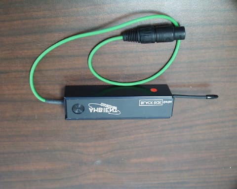
Click to zoom
Application Details
- Equipment Class
- DXX - Part 15 Low Power Communication Device Transmitter
- Date of Grant
- Dec 18, 2000
- Application Purpose
- Original Equipment
- Date of Application
- Dec 18, 2000
- Equipment Note
- Timecode Wireless Link
- Frequency Range
- 914.00000000 - 915.00000000
- Company
- Ambient Recording GmbH
- Country
- Germany
Documents & Files
Document Text
Text extracted from the exhibit documents filed with the FCC. Open a document above to read the original.
Users Manual
BBTX915 Operations Manual The BBTX915 transmitter module is to be used for transmitting the timecode data to the appropriate receiver-display combination. These units may have a range of up to fifty meters but in certain circumstances can be greater. The transmitter is designed to be connected to a timecode generator. The information is then sent to the receivers over the wireless link. To use the BBTX915, simply attach a timecode generator to the input of the BBTX915 and turn the unit on. The units are powered from a nine-volt battery, be sure there is a fresh battery installed. The ACD Master Timecode Slate/Radio may be used to receive the timecode information from the BBTX915. Regulatory Statements: This device complies with Part 15 of the FCC Rules. Operation is subject to the following two conditions: (1) This device may not cause harmful interference, and (2) this device must accept any interference received, including interference that may cause undesired operation. Caution: Changes or modifications not expressly approved by Ambient Recording GmbH, the party responsible for compliance, will void the user’s authority to operate the equipment. Information to User: NOTE: This equipment has been tested and found to comply with the limits for a Class B digital device, pursuant to part 15 of the FCC Rules. These limits are designed to provide reasonable protection against harmful interference in a residential installation. This equipment generates, uses and can radiate radio frequency energy and, if not installed and used in accordance with the instructions, may cause harmful interference to radio communications. However, there is no guarantee that interference will not occur in a particular installation. If this equipment does cause harmful interference to radio or television reception, which can be determined by turning the equipment off and on, the user is encouraged to try to correct the interference by one or more of the following measures: -Reorient or relocate the receiving antenna. -Increase the separation between the equipment and receiver. -Connect the equipment into an outlet on a circuit different from that to which the receiver is connected. -Consult the dealer or an experienced radio/TV technician for help.
Block Diagram
Block Diagram for Ambient Recording GmbH Model BBTX915 FCC ID PDZ ACDTXRX915
External Photos
External Photos
ID Label/Location Info
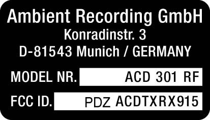
FCC ID Label Location Ambient Recording GmbH Model BBTX915 FCC ID PDZ ACDTXRX915
Internal Photos
Internal Photos
Operational Description
Operational Description for Ambient Recording GmbH Model: BBTX915 FCC ID: PDZ ACDTXRX915
Schematics
Circuit Schematic for Ambient Recording GmbH Model: BBTX915 FCC ID: PDZ ACDTXRX915
Test Report
ENGINEERING TEST REPORT FOR APLLICATION of GRANT of CERTIFICATION FOR CFR 47, PART 15C - INTENTIONAL RADIATORS For AMBIENT RECORDING GmbH Konradinstr. 3 D-81543 Munich Germany Chris Price, TIMECODE TRANSMITTER Model: BBTX915 Frequency 914.5 MHz FCC ID#: PDZ ACDTXRX915 Test Date:November 16, 2000 Certification Date:November 16, 2000 Certifying Engineer: Scot D. Rogers ROGERS LABS, INC. 4405 West 259 th Terrace Louisburg, KS 66053 Phone: (913) 837-3214 FAX: (913) 837-3214 This report shall not be reproduced except in full, without the written approval of the laboratory. This report must not be used by the client to claim product endorsement by NVLAP or any agency of the U.S. Government. ROGERS LABS, INC. 4405 West 259 th Terrace Louisburg, KS 66053 Phone / Fax (913) 837-3214 NVLAP Accredited LaboratoryNVLAP Lab Code: 200087-0 ROGERS LABS, INC.Ambient Recording GmbH 4405 W. 259th TerraceMODEL: Timecode Transmitter Louisburg, KS 66053Test #: 001113FCCID#: PDZ ACDTXRX915 Phone/Fax: (913) 837-3214Test to: FCC Parts 2 and 15cPage 2 of 26 certification\Ambntbbtx.doc 12/08/2000 TABLE OF CONTENTS FORWARD:.....................................................................................................................3 1)APPLICABLE STANDARDS & TEST PROCEDURES.............................................3 2.1033(b)Application for Certification..............................................................................................................4 2)EQUIPMENT TESTED...............................................................................................5 3)EQUIPMENT FUNCTION AND TESTING PROCEDURES.......................................5 4)EQUIPMENT AND CABLE CONFIGURATIONS......................................................5 Conducted Emission Test Procedure.................................................................................................................5 Radiated Emission Test Procedure:...................................................................................................................5 5)LIST OF TEST EQUIPMENT.....................................................................................6 6)UNITS OF MEASUREMENTS...................................................................................7 7)TEST SITE LOCATIONS...........................................................................................7 8)SUBPART B – UNINTENTIONAL RADIATORS.......................................................7 Conducted EMI...................................................................................................................................................7 Radiated EMI......................................................................................................................................................7 Data: Conducted (6 Highest Emissions)...........................................................................................................9 Data: General Radiated (6 Highest Emissions)................................................................................................9 Summary of Results for Conducted Emissions.................................................................................................9 Summary of Results for Radiated Emissions....................................................................................................9 Statement of Modifications...............................................................................................................................10 9)SUBPART C - INTENTIONAL RADIATORS...........................................................10 15.203 Antenna Requirements..........................................................................................................................10 Restricted Bands of Operation Per 15.205......................................................................................................10 Data 15.205.......................................................................................................................................................11 15.209 Radiated Emissions Limits; General Requirements...........................................................................11 Radiated EMI....................................................................................................................................................11 Data 15.209:......................................................................................................................................................12 Summary of Results for Radiated Emissions:...................................................................................................13 15.249 Operation in the Band 902-928 MHz...................................................................................................13 Radiated Emissions of Intentional Radiator......................................................................................................16 Statement of Modifications...............................................................................................................................17 NVLAP Accredited LaboratoryNVLAP Lab Code: 200087-0 ROGERS LABS, INC.Ambient Recording GmbH 4405 W. 259th TerraceMODEL: Timecode Transmitter Louisburg, KS 66053Test #: 001113FCCID#: PDZ ACDTXRX915 Phone/Fax: (913) 837-3214Test to: FCC Parts 2 and 15cPage 3 of 26 certification\Ambntbbtx.doc 12/08/2000 FORWARD: The following is submitted for consideration in obtaining a Grant of Certification for low power intentional radiators per CFR Paragraph 15.249. Name of Applicant: AMBIENT RECORDING GmbH Konradinstr. 3 D-81543 Munich Germany Model: BBTX915 TIMECODE TRANSMITTER FCC I.D.:PDZ ACDTXRX915 Frequency Range: 914.5 MHz Operating Power: Less than 50 mV/m @ 3 Meters (94 dBμV/m @ 3 meters) 1)Applicable Standards & Test Procedures a) In accordance with the Federal Communications Code of Federal Regulations, dated October 1, 1999, Part 2, Subpart J, P…
Text truncated - open the document above for the full version.
Test Setup Photos
Test Set-up Photos
Contact Information
Applicant
Guenter Knon(CEO)
Test Firm
Rogers Labs, Inc.Scot Rogers
Technical Specifications
| # | Rule Parts | Frequency Range | Power Output |
|---|---|---|---|
| 1 | 15C | 914 MHz - 915 MHz | - |