PETCSRXTXCigar Humidity Sensor & Transmitter
Nuventions, Inc.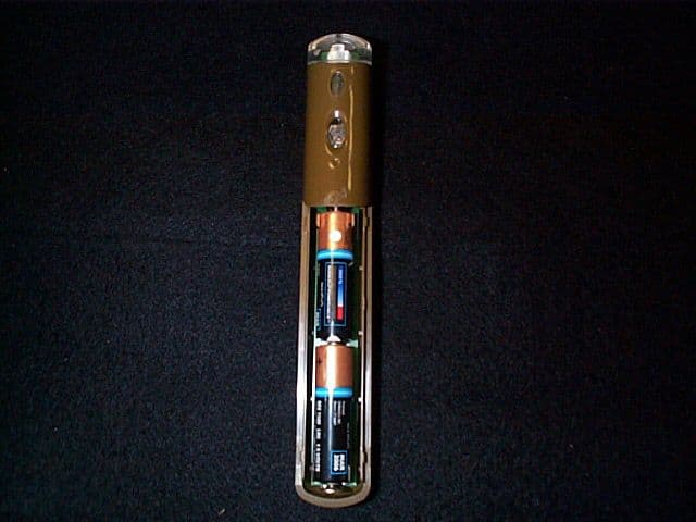
Click to zoom
Application Details
- Equipment Class
- DSC - Part 15 Security/Remote Control Transmitter
- Date of Grant
- Mar 11, 2001
- Application Purpose
- Original Equipment
- Date of Application
- Dec 18, 2000
- Equipment Note
- Cigar Humidity Sensor & Transmitter
- Frequency Range
- 315.00000000 - 315.00000000
- Company
- Nuventions, Inc.
- Country
- United States
Documents & Files
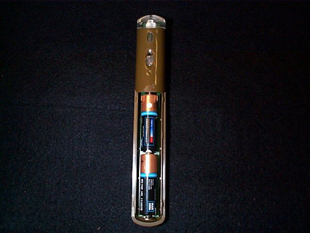
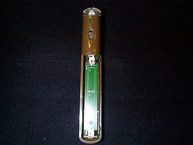
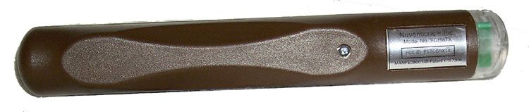
Document Text
Text extracted from the exhibit documents filed with the FCC. Open a document above to read the original.
Users Manual
User Instructions C i g a r S e n t r y ™ Sa ve these Use and Car e Instructions WARNING: When using electrical appliances basic safety precautions should always be followed, including the following: nPlease read all instructions. nWARNING:To reduce risk of fire, electrical shock or injury: nDo not allow to be used as a toy. Close supervision is necessary when any appliance is used by or near children. nDo not use outdoors, on or near hot or wet surfaces. nUse only as described in this manual. nDo not use the Cigar Sentry in any containers that contain toxic sub- stances, flammable or combustible liquids such as gasoline, or oper- ate in the presence of explosive or flammable fumes. nDo not disassemble the Cigar Sentry under any circumstances. Disassembly will void the warranty in its entirety; see W arranty and Servicefor more information. Disasssembly may result in elec- trical shock or fire. There are no consumer serviceable parts inside. Important Safeguards This device complies with part 15 of the FCC Rules. Operation is subject to the following two conditions: (1) This device may not cause harmful interference, and (2) this device must accept any interference received, including interference that may cause undesired operation. 1.Place 2 AA batteries in the sensor unit (Fig. 1). 2.Plug the alarm unit (Fig. 2) into a wall outlet within 50 feet of the cigar storage container (maximum distance may vary). The green LED should illuminate. 3. TESTSYSTEM: T o test the transmission range of the Cigar Sentry , place the sensor unit near you storage container , but not in it. Plug the receiver unit into a nearby outlet. The receiver should beep or the Green LED will blink about every 10 seconds. If not, your alarm unit is out of transmission range and should be moved to a dif ferent out- let or one that is closer to your cigar container . Orientation of sensor and receiver will impact maximum achievable distance as does the presense of metal such as doors, appliances, etc. Keep the system Figure 1: Sensor Unit How To Use Battery Low Humidity OK Check Humidity Figure 2: Alarm Unit Test Button LED Sound On/Of f Switch LED Indicators as far away from metal as possible for best results. You can also momentarily press the sensor’s test button to check range. This will illuminate all receiver LEDs and a beep will be heard. Not that holding the sensor unit will reduce effective transmission range. 4.Make sure the humidity level in your cigar storage container is at the desired level (70% is considered optimum). 5.CALIBRATE: Press and hold the sensor test button for approximately 4 seconds until the green LED on the alarm unit blinks once and/or a single beep is heard (sound switch must be in the “On” position). Quickly place the sensor unit into your cigar storage container. The system will now pause for 10-15 minutes and then sample the ambi- ent humidity inside the container and automatically calibrate. Once the green LED on the alarm begins blinking (every 10 seconds), the system is calibrated. It is imperative that you first follow step 4 above. The humidity in your cigar storage container must be at the desired level prior to calibrating the Cigar Sentry. 1.Humidity OK: If the humidity level in your container is within approxi- mately +/- 5% of the calibrated level, the green LED on the alarm unit will be illuminated. The sensor unit checks the humidity level every 10 seconds. The green LED blinks “off” on every check. 2.Check Humidity: If the current humidity level is approximately 5% RH above or below the calibrated level, an alarm condition will be indi- cated by a “beep” (if the sound button is in the “On” position) and the red LED will be illuminated on the alarm unit. 2.Other alarm conditions: When you open your storage container, the Cigar Sentry may exhibit an alarm condition, because the humidity will change beyond the acceptable level. We recommend closing your container as quickly as possible to minimize moisture loss. Your container will go back to the desired humidity in a few minutes and Cigar Sentry will go back to “Humidity OK” mode. The time it takes to return to this acceptable state will depend on how well your humidifi- cation device can re-establish the lost moisture. If it takes more than 5 minutes your humidification device may need to be refilled. On-going Operation 1.SOUNDON/OFF: A beeper sound on/off switch on the alarm unit can be set to the desired position. Factory default is “On.” 2.BATTERY LOW INDICATOR: When the Battery Low Indicator is illu- minated (yellow LED) on the alarm unit, the batteries in the sensor unit should be replaced. 3.SYSTEMTEST: A momentary press of sensor test button will cause all receiver unit LEDs to illuminate and a beep to sound (if sound switch is in the “ON” position. This also verifies that signal transmis- sions are being received. 1.RECEIVER: Green LED does not illuminate. Verify that the outlet is working with another appliance. If it is, then the receiver may be defective. Please contact Customer Service. 2.TRANSMITTER: Red LED does not illuminate when the test button is depressed. Check orientation of batteries and that metal battery clips are in contact with batteries. Don’t forget to verify that the batteries are good. 3. RECEIVER: Green LED does not blink every 10 seconds. The trans- mitter is out of range. Move the receiver to a dif ferent outlet and pos- sibly one closer to the transmitter . OR the sensor is in calibrate mode. It takes approximately 10-15 minutes to cailbrate and the LED will not begin blinking until calibration has been completed. 4.ALARM: The receiver alarms intermittently. If your storage container is drafty, there is a lot of air movement inside, or the door is opened frequently, humidity may vary enough to cause the unit to alarm. Move the sensor to a place where there is least air movement. Other Features Troubleshooting 1.The receiver unit indicates an alarm condition, but my storage con- tainer’s humi…
Text truncated - open the document above for the full version.
Cover Letter(s)
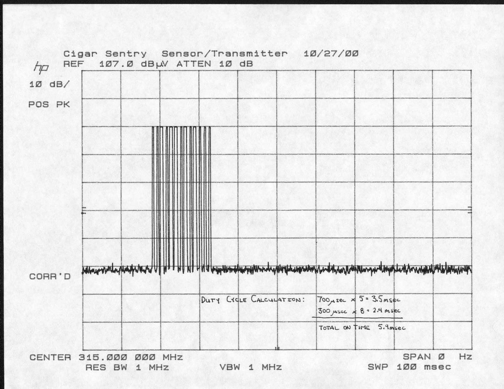
To: Mr. Andy Leimer FCC Application Processing Branch Re: FCC ID PETCSRXTX Applicant: Nuventions, Inc. 731 Confirmation Number: EA99568 This is a letter in response to your e-mail dated 02.08/01 (Technical request). Yes, there is a transmission every 10 seconds. Therefore, you are correct, it should fall under the provisions of section 15.231(e). The new data is uploaded with this letter. The manufacturer verified and declared that this device operated under the provisions of section (e) is provided with a means for automatically limiting operation so that the duration of each transmission shall not be greater than one transmission but in no case less than 10 seconds. Please do not hesitate to contact me again if you have additional questions and/or comments. Sincerely, Tho mas K. Ha
ID Label/Location Info
Nuventions™Inc. Model No. ECHATX MANFE0800 US Patent 6157306 FCC ID: PETCSRXTX
Schematics
8 8 7 7 6 6 5 5 4 4 3 3 2 2 1 1 DD CC BB AA B-2998 MADE FOR: MULARONI 0 HUMIDITY ALARM SYSTEM (TRANSMITTER) B 11Thursday, June 22, 2000 Title SizeDocument NumberRev Date:Sheetof BT1 3V ANT1 U4 TLC555M R4 1K Q1 MMBT3906 Y1 4MHz C1 ..1 uF C2 ..1 uF C6 ..001 uF Y2 315 Mhz U3 ZSM300C S1 Q2 MMBT3904LT1 R5 18K R6 100 L4 180 nH C4 5.0 pF D1 LED/RED C5 12 pF SEN1 SENSOR L3 180 nH C3 1000 pF L1 18 nH R3 1K R1 604K L2 150 nH U5 PIC12CE518 1 2 1 TRIG 2 RSET 4 DSCH 7 THRES 6 CON 5 GND 1 VDD 8 OUT 3 1 2 1 32 1 2 3 1 2 1 2 1 2 1 2 VIN 2 VOUT 1 GND 3 32 14 1 2 3 1 2 1 2 12 1 2 1 2 1 2 1 2 12 1 2 1 2 1 2 1 2 12 VDD 1 OSC1 2 OSC2 3 GP3 4 GP2 5 GP1 6 GP0 7 VSS 8 TRANSMITTER 315MHZ OOK (SAW STABILIZED OSCILLATOR) BATTERY MONITOR TEST SURFACE MOUNT TRANSMITTER SECTION ECHATRANS-SM.DSN
Test Report
Document No. NUV-001DEUT: Cigar Sentry TransmitterDate: 12/11/001 of 27 FCC Certification / Technical Report FCC Test Specification : Certification for FCC Part 15, Subpart C §15.231 Manufacturer : Nuventions, Inc. Equipment Under Test : Wireless Humidity Alarm Transmitter Model Cigar Sentry Test Report No. : NUV-001D Purchase Order No. : 2007 Document History RevisionIssue DateAffected Pages Description of ModificationsRevised By Approved By N/C 11 December, 2000 Initial release Document No. NUV-001DEUT: Cigar Sentry TransmitterDate: 12/11/002 of 27 FCC Certification / Technical Report Document No. NUV-001D From G&M Compliance, Inc. (Garwood Laboratories) Test for Nuventions, Inc. Wireless Humidity Alarm Transmitter Model Cigar Sentry W RITTEN B Y R EVIEWED B Y Thomas K. Ha Thomas K. HaThomas K. Ha Thomas K. HaEdward Nakauchi Edward NakauchiEdward Nakauchi Edward Nakauchi Thomas K. Ha EMC Technical Report Writer Ed Nakauchi EMC Chief Engineer NARTE, Certified Test PersonnelTest Dates Arnie Tapia – EMC Engineer27 October - 28 November, 2000 Test Facility Address City, State, Zip Code Phone Fax G&M Compliance, Inc. (Garwood Laboratories) 565 Porter Way Placentia, CA 92870 (714) 927-1900 (714) 927-1901 This report may be reproduced in full, partial reproduction may only be made with the written consent of the laboratory. The results in this report apply only to the equipment tested. This report may not be used to claim product endorsement by NVLAP or any agency of the U.S. government. Document No. NUV-001DEUT: Cigar Sentry TransmitterDate: 12/11/003 of 27 TABLE OF CONTENTS (This document contains a total of 27 pages, excluding attachments) MEASUREMENT / TECHNICAL REPORT SUMMARY............................................................................ 4 1. GENERAL INFORMATION ................................................................................................................... 5 1.1 Product Description...................................................................................................... 5 1.2 Related Submittal(s)/ Grant(s)...................................................................................... 5 1.3 Tested System Description ............................................................................................ 5 1.4 Test Methodology .......................................................................................................... 6 1.5 Test Facility.................................................................................................................. 7 2. PRODUCT LABELING.......................................................................................................................... 8 2.1 FCC ID Label................................................................................................................8 2.2 Location of Label on EUT............................................................................................. 8 2.3 Information to the User ................................................................................................ 8 3. SYSTEM TEST CONFIGURATION ....................................................................................................... 9 3.1 Justification................................................................................................................... 9 3.2 EUT Exercise Software/Equipment .............................................................................. 9 3.3 Special Accessories....................................................................................................... 9 3.4 Equipment Modifications.............................................................................................. 9 3.5 Configuration of Tested System.................................................................................. 10 3.6 Details of Tested System ............................................................................................. 10 4. BLOCK DIAGRAM(S) OF EUT ........................................................................................................... 11 5. TEST MEASUREMENT AND EUT PHOTOS ...................................................................................... 12 6. TEST DATA .......................................................................................................................................... 19 6.1 General Radiated Emissions Requirements ............................................................... 19 6.2 General Radiated Emissions Results .......................................................................... 19 6.3 Field Strength of Emissions Requirements................................................................. 20 6.4 Summary Table for Highest Field Strength Levels.................................................... 21 6.5 Field Strength Calculation ......................................................................................... 22 6.6 Occupied Bandwidth ................................................................................................... 23 APPENDIX A - TEST EQUIPMENT USED........................................................................................... 24 APPENDIX B - SUPPLEMENTAL TEST DATA..................................................................................... 25 ATTACHMENTS.................................................................................................…
Text truncated - open the document above for the full version.
Test Report
FCC Part 15, Subpart C, § 15.231(e) Limit Table Fundamental Frequency (MHz) Field Strength of Fundamental (μV/m) Field Strength of Spurious Emissions (μV/m) 40.66-40.701,000100 70-13050050 130-174500 to 1,500*50 to 150* 174-2601,500150 260-4701,500 to 5,000*150 to 500* Above 4705,000500 *Linear Interpolations. The following formula was used to calculate the limit: (16.6667) x f (MHz) – (2833.3333) μV/m = Limit, for a test distance of 3 meters, where f (MHz) is the Equipment Under Test’s fundamental frequency. The fundamental frequency of the EUT is 315.0 MHz. The applicable limits for the Equipment Under Test are those listed for the fundamental frequency falling within the frequency band of 260-470 MHz. Test Results: Company Name: Cigar Sentry EUT Name: Wireless Humidity Alarm (Sensor/transmitter) (MODEL C) Operating Frequency: 315.0 MHz Field Strength of Emissions from an Intentional Radiator (Reference: FCC Pt.15 Subpart C, §15.231(e)) FCC Average Limit for the Fundamental: (16.6667) x f (MHz) – (2833.3333) μV/m @3meters = 2,416.67 μV/m FCC Average Limit for the Harmonics: 241.66μV/m Polarity (V &H) Frequency (MHz) S.A. Reading Peak (dBμV) Correction Factor (dB) Peak Field Strength at 3 meters (dBμV/m) Peak Field Strength at 3 meters (μV/m) Average Field Strength at 3 meters (μV/m) FCC Limit at 3 meters (μV/m) V31581.8-6.575.35,821.03-2,416.67 H31594.2-6.587.724,266.102,426.612,416.67 V63052.61.954.5530.8853.08241.66 H63062.31.964.21,621.81162.18241.66 V94530.57.037.574.99-241.66 H94537.07.041.0112.20-241.66 V126047.50-4.0943.41148.08-241.66 H126055.80-4.0951.71385.0338.50241.66 V157540.20-1.2638.9488.51-241.66 H157548.40-1.2647.14227.51-241.66 V1890NDS1.58NDSNDSNDS241.66 H1890NDS1.58NDSNDSNDS241.66 V2205NDS3.73NDSNDSNDS241.66 H220534.103.7337.8377.89-241.66 V2520NDS5.46NDSNDSNDS241.66 H2520NDS5.46NDSNDSNDS241.66 V2835NDS6.61NDSNDSNDS241.66 H2835NDS6.61NDSNDSNDS241.66 V3150NDS8.15NDSNDSNDS241.66 H3150NDS8.15NDSNDSNDS241.66 - Average emission measurements were employed and the provisions in §15.35 for averaging pulsed emissions and for limiting peak emissions were followed. - NDS (No Detectable Signal)
Test Setup Photos
Radiated Emissions
Test Setup Photos
Radiated Emissions
Contact Information
Applicant
Marco Mularoni(President)
Test Firm
Garwood Laboratories, Inc.Jason Armstrong
714-572-2027Fax: 714-572-2025
Technical Specifications
| # | Rule Parts | Frequency Range | Power Output | Tolerance |
|---|---|---|---|---|
| 1 | 15C | 315 MHz - 315 MHz | - | % |