PEXTW2208-01-1300RC Car
Toys World Electronic Limited
Click to zoom
Application Details
- Equipment Class
- CRR - Superregenerative Receiver
- Date of Grant
- Mar 18, 2003
- Application Purpose
- Original Equipment
- Date of Application
- Mar 18, 2003
- Equipment Note
- RC Car
- Frequency Range
- 49.86000000 - 49.86000000
- Country
- Hong Kong
Documents & Files
Document Text
Text extracted from the exhibit documents filed with the FCC. Open a document above to read the original.
Users Manual
OPERATING THE VEHICLE AND THE TRANSMITTER RADIO INTERFERENCE This de vic e complies wit h Part 15 of the FCC rules. Operation is subject to the followin g conditions: (1)This devic e may not cause ha rmful int erference, and (2)this devic e mus t ac cep t any in terference received, in clu ding int erf er ence that may cause undesired operat io n. When your R/C Vehicle runs erratic ally or loss of control, the problem is due to being in an area near High Tension Wires, Telephone Poles wit h High-Volt age Transformers, CB Radios, ev en certain Building or other R/C Vehicle running close by on the same Fre quency as yours, You may have to choose dif ferent locat ion. 1. Swit ch Vehicle to ON po sit ion. 2. Adjust St eering Alignmen t Lever Left or Rig ht when the stee ring is not properly aligned. 3. Operate your veh ic le in a cle an, dry, open area, do not drive in the street. Avoid sand and water . 4. Do not operate your Vehicle too far away from the transmit ter , your signal strength will become weak and Vehicle will not function properly. The maxim um range for the Vehicle sho uld be be tween 20 to 30 feet (7 to 10 met res), when operating outdoor. 5. For bes t result s, hold Transmit ter an tenna up , not point ed down toward R/C Vehicle. 6. Turn Vehicle swit ches to OFF pos it ion when not in us e. CAUTION WHEN USING BATTERIES WARNING: FCC Regulations stat e that Changes or modific ations to this un it not ex pressly ap proved by the party responsible for compliance could voi d the us er s authority to op erate the equipment. This eq uipment has been tested and fou nd to comply wit h the limit s for a class B digital device, pursuant to Part 15 of the FCC Rules. These li mit s ar e designed to provide reasonable protec tion against harmful int erf er ence in a residential installation. This eq uipment generates us e and can radiate radio frequency en ergy an d, if not installed and sue d in ac cordance wit h the ins tructions, may cause ha rmful int erference to radio communicat ions. However , there is no guarantee that int erference will not oc cur in a partic ular installation. If this equipment does cau se harmful int erf erence to radio or television reception, whi ch can be det er min ed by turning the int er ferenc e by one or mor e of the following measures: NOTE: Reorient or relocat e the receiving antenna. Inc rease the separation betwee n the equipment and receiver . Connect the equipment int o an outlet on a circ uit dif ference from tha t to which the rec eiv er is needed. Consult the dealer or an ex perienced radio / TV tec hnicia n for help. Ins tall 3 X "AAA" alkaline(1.5V) batteries wit h polarit y as shown ins id e batter y compartment TRANSMITTER ANTENNA INSTALLATION Place the transmit ter antenna in to antenna holder and screw it in clockwis e. If the antenna is not screwed in sec urely, the vehicle may mov e erratic ally. Screw the antenna sec urely. 3. Red LED light in dicates that veh ic le is Cha rging. Whe n LED light goes of f, charging has been completed. 2. Vehicle has rechargeable NI-MH bat tery. Quick boost charge the vehicle for 2 minutes by placing the vehicle on Charger platform correctly (S ee diagram Fig. 1b ) 1. Ins ert 3 AAA alkaline batteries (ex cluded) Wit h the correct po larity in charger. align (-) and (+ ) accordingly.(See diagram Fig. 1a ) 3 x AAA batteries CHARGE Twis t bottle counterclockwis e to separate Charger and Remot e Transmit ter . Open the Widow and tak e out the Antenna and the Vehicle. Antenna Battery cov er Controller CHARGE THE VEHICLE TRANSMITTER TRANSMITTER CONTROLS STEERING CONTROL PREPARATION CONTACTS (F ig. 1a )(F ig. 1b ) TU RB O Bottle Charger Transmit ter Not suit able for children under 36 months due to small parts only. * Pleas e keep thi s manual sinc e it contains impo rt an t inf ormat io n. Made in China Nev er mix alkaline / standard (c arbon-zinc) and rechargeable (nickel cadmium) ba tteries. Non-rechargeable batteries are not to be re cha rged. Rec hargeable AAA ba tteries ar e to be remov ed from the toy before being charged. Packaging screws mus t be remov ed by an adult. Dif ferent types of ba tteries or new and us ed batter ies ar e not to be mix ed. Only batteries of the same as equivalent type as recommended ar e to be us ed. Batteries are to be in ser ted wit h the correct polarity. Exhausted batter ies ar e to be remov ed from the toy s. The supply terminals are not to be sho rt -circ uit ed. Nev er let the charger or vehicle get wet or damp. Rec hargeable bat teries may on ly be charged under the supervis io n of an adult . Alway s keep clean the contacts on the charger and those on the vehicle. T U R B O TURBO LEFT TURN RIGHT TURN DIRECTION CONTROL FORWARD REVERSE PI-2208N1-01
External Photos
INTERTEK TESTING SERVICES Ophoto1 Ophoto2 INTERTEK TESTING SERVICES Ophoto3
Internal Photos
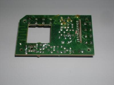
INTERTEK TESTING SERVICES Iphoto1 Iphoto2 INTERTEK TESTING SERVICES Iphoto3 Iphoto4
Operational Description
FCC ID: PEXTW2208-01-1300 Technical Description : The brief circuit description is listed as follows : - Q18 and associated circuit act as RF Amplifier and demodulator. - Q13, Q14, 21, 22 and associated circuit act as Steering Motor Driver. - Q16, 17, 23, 24 and associated circuit act as Racing Motor Driver. - U2 and associated circuit act as Decode IC. Antenna Used : A permanent wire antenna has been used.
Test Report
•The test results reported in this report shall refer only to the sample actually tested and shall not refer or be deemed to refer to bulk from which such a sample may be said to have been obtained. •This report shall not be reproduced except in full without prior authorization from Intertek Testing Services Hong Kong Limited •The evaluation data of the report will be kept for 3 years from the date of issuance. FCC ID : PEXTW2208-01-1300 Toys World Electronic Limited Application For Certification (FCC ID: PEXTW2208-01-1300) Superregenerative Receiver Model : TW-2208 WO# 0300870 CKL/at February 19, 2003 INTERTEK TESTING SERVICES FCC ID: PEXTW2208-01-1300 i LIST OF EXHIBITS INTRODUCTION EXHIBIT 1:General Description EXHIBIT 2:System Test Configuration EXHIBIT 3:Emission Results EXHIBIT 4:Equipment Photographs EXHIBIT 5:Product Labelling EXHIBIT 6:Technical Specifications EXHIBIT 7:Instruction Manual EXHIBIT 8:Miscellaneous Information INTERTEK TESTING SERVICES FCC ID: PEXTW2208-01-1300 ii MEASUREMENT/TECHNICAL REPORT Toys World Electronic Limited - MODEL: TW-2208 FCC ID: PEXTW2208-01-1300 February 19, 2003 This report concerns (check one:)Original Grant X Class II Change Equipment Type: Superregenerative Receiver (example: computer, printer, modem, etc.) Deferred grant requested per 47 CFR 0.457(d)(1)(ii)?Yes No X If yes, defer until: date Company Name agrees to notify the Commission by: date of the intended date of announcement of the product so that the grant can be issued on that date. Transition Rules Request per 15.37?Yes No X If no, assumed Part 15, Subpart B for intentional radiator Report prepared by:C. K. Lam Intertek Testing Services 2/F., Garment Center, 576, Castle Peak Road, HONG KONG Phone:852-2173-8502 Fax:852-2742-9149 INTERTEK TESTING SERVICES FCC ID: PEXTW2208-01-1300 iii Table of Contents 1.0 General Description......................................................................................................................2 1.1 Product Description..................................................................................................................2 1.2 Related Submittal(s) Grants.....................................................................................................2 1.3 Test Methodology.....................................................................................................................3 1.4 Test Facility...............................................................................................................................3 2.0 System Test Configuration..........................................................................................................5 2.1 Justification...............................................................................................................................5 2.2 EUT Exercising Software.........................................................................................................5 2.3 Support Equipment List and Description................................................................................5 2.4 Equipment Modification..........................................................................................................6 2.5 Special Accessories...................................................................................................................6 3.0 Emission Results...........................................................................................................................8 3.1 Field Strength Calculation........................................................................................................9 3.2 Radiated Emission Configuration Photograph.....................................................................10 3.3 Radiated Emission Data.........................................................................................................11 4.0 Equipment Photographs............................................................................................................14 5.0 Product Labelling.......................................................................................................................16 6.0 Technical Specifications.............................................................................................................18 7.0 Instruction Manual.....................................................................................................................20 8.0 Miscellaneous Information........................................................................................................22 8.1Stabilization Waveform..........................................................................................................23 8.2 Emissions Test Procedures.....................................................................................................24 8.2 Emissions Test Procedures (cont'd).......................................................................................25 INTERTEK TESTING SERVICES FCC ID: PEXTW2208-01-1300 iv List of attached file Exhibit typeFile Descriptionfilename Test ReportTest Reportreport.pdf Operation DescriptionTechnical Descriptiondescri.pdf Test Setup PhotoRadiated Emissionradiated photos.pdf Test ReportBandwidth Plotbw.pdf External PhotoExternal Photoexternal photos.pdf Internal PhotoInternal Photointernal photos.pdf Block DiagramBlock Diagramblock.pdf SchematicsCircuit Diagramcircuit.pdf ID Label/LocationLabel Artwork and Locationlabel.pdf User ManualUser Manualmanual.pdf INTERTEK TESTING SERVICES FCC ID: PEXTW2208-01-1300 1 EXHIBIT 1 GENERAL DESCRIPTION INTERTEK TESTING SERVICES FCC ID: PEXTW2208-01-1300 2 1.0General Description 1.1Product Description The equipment under test (EUT) is a receiver for a RC car operating at 49.860 MHz. The EUT is powered by two 1.2 v rechargeable batteries. The EUT can be controlled to move forward or backward and to turn left or right by the controller. The brief circuit description is saved with filename: descri…
Text truncated - open the document above for the full version.
Test Setup Photos
INTERTEK TESTING SERVICES Front View Back View
Contact Information
Applicant
Simon Wong(Marketing Manager)
Technical Contact
Intertek Testing Services Hong Kong Ltd.Wilbur Ng
[email protected]852-2173-8502
2/F., Garment Centre, · Kowloon, · Hong Kong
Non-Technical Contact
Intertek Testing Services Hong Kong Ltd.Wilbur Ng
[email protected]852-2173-8502
Test Firm
Intertek Testing Services Hong KongBilly Chow
Technical Specifications
| # | Rule Parts | Frequency Range | Power Output |
|---|---|---|---|
| 1 | 15B | 49.86 MHz - 49.86 MHz | - |
Other Applications from Toys World Electronic Limited
PEX72574T27
Nov 01, 2006Radio Control Toy Transmitter
Equipment Class
DXX - Part 15 Low Power Communication Device Transmitter
PEXTW2206-49-2200
Mar 16, 2004RC Car
Equipment Class
CRR - Superregenerative Receiver
PEXTW2206-49-2100
Mar 15, 2004RC Car
Equipment Class
DXX - Part 15 Low Power Communication Device Transmitter
PEX29012-49-43000
Feb 09, 2004RC Car
Equipment Class
CRR - Superregenerative Receiver
PEXTW2207-27-2000
Jun 19, 2003RC Car
Equipment Class
DXX - Part 15 Low Power Communication Device Transmitter