PF3PX50PX50 PROFESSIONAL STEREO TRANSMITTER
Ramsey Electronics, Inc.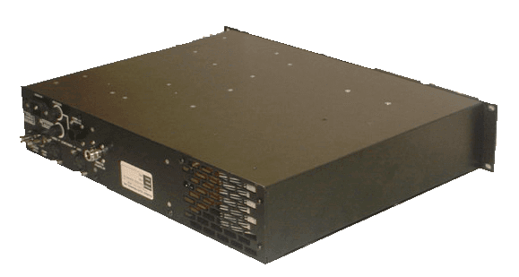
Click to zoom
Application Details
- Equipment Class
- TBC - Licensed Broadcast Station Transmitter
- Date of Grant
- May 03, 2004
- Application Purpose
- Original Equipment
- Date of Application
- May 03, 2004
- Equipment Note
- PX50 PROFESSIONAL STEREO TRANSMITTER
- Frequency Range
- 87.50000000 - 108.10000000
- Company
- Ramsey Electronics, Inc.
- Country
- United States
Documents & Files
Document Text
Text extracted from the exhibit documents filed with the FCC. Open a document above to read the original.
Users Manual
PX50 COMMERCIAL FM STEREO TRANSMITTER PX50 COMMERCIAL FM STEREO TRANSMITTER Owner’s Manual Copyright 2003 by Ramsey Electronics Inc. No part of this publication may be duplicated in part or whole without written permission of Ramsey Electronics Inc. Ramsey Electronics Inc. 590 Fishers Station Drive Victor, NY 14564 Tel: 585-924-4560 Fax: 585-924-4555 2 FCC Labeling, Warning and Information to User Requirements This equipment has been tested and found to comply with the limits for a Class A digital device, pursuant to Part 15 of the FCC Rules. These limits are designed to provided reasonable protection against harmful in- terference when the equipment is operated in a commercial environment. This equipment generates, uses, and can radiate radio frequency energy and, if not installed and used in accordance with the instruction manual, may cause harmful interference to radio communications. Operation of this equipment in a resi- dential area is likely to cause harmful interference in which case the user will be required to correct the in- terference at his own expense. Warning: Changes or modifications not expressly approved by Ramsey Electronics, Inc. could void the user’s authority to operate the equipment This device complies with Part 15 of the FCC Rules. Operation is subject to the following two conditions: (1) this device may not cause harmful interference and (2) this device must accept any interference re- ceived, including interference that may cause undesired operation. 3 PX50 COMMERCIAL FM STEREO TRANSMITTER Ramsey Publication No. MPX50 Price $10.00 TABLE OF CONTENTS Introduction .........................................................4 Using the PX50 Interface .....................................5 Setting Operating Frequency..............................8 PX50 connections ................................................9 Programming the PX50........................................10 Appendix A ..........................................................13 Appendix B ..........................................................14 Appendix C ..........................................................16 Specifications.......................................................18 Warranty ...............................................................19 INSTRUCTION AND CALIBRATION MANUAL FOR RAMSEY ELECTRONICS, INC. 590 Fishers Station Drive Victor, New York 14564 Phone (585) 924-4560 Fax (585) 924-4555 www.ramseyelectronics.com 4 INTRODUCTION The PX 50 is a 50 Watt FM Stereo Transmitter/ Exciter. It is frequency-agile, and can be programmed via the front panel to any frequency within the 87.5 to 108.1 MHz commercial FM broadcast band. Output power is adjustable from 1 to 50 watts. The Interface Screen, is a 2 by 20 line Vacuum Fluorescent display. In order to show more information in a small space, options have been broken up into different screens or “pages”. There are 14 screens for the PX50; 9 are adjustment screens, meaning they contain values you can change, and 5 are informational screens containing diagnostics information that you cannot change. There are 5 buttons used to navigate the display screens and to update settings. The up and down buttons move through the display “pages”. The left and right buttons are used to make adjustments to displayed parameters. An “enter” key programs new settings into the PX50. 5 USING THE PX50 INTERFACE This brief tutorial on your PX50 will help you navigate the interface more efficiently. Here is the list of menu items in order which is accessed using the up down keys. 1.General Display. The PX50 defaults to this screen upon power up. It displays frequency, left and right audio levels, the PLL lock, transmitter temperature, and the RF power output. 2.Audio Display. This displays the left and right peak hold meters for modulation level setting. 0dBm is five full bars from the right of the display. Try not to exceed this level since it represents close to 100% modulation. 3.VSWR (Voltage Standing Wave Ratio) Display. This screen displays the current forward power, re- verse power, and VSWR of your antenna - amplifier match. If the VSWR is very poor, the PX50 will automatically reduce power to protect the amplifier stage from damage. Ideally VSWR should be 1.25 or less (1.0 is a perfect match). A higher VSWR indicates a poorer antenna match. This results in re- duced transmission range, higher operating temperature in the power amplifier stage, and could shorten the expected life of some components. 4.Temperature Display. This allows you to monitor the running temperature of both amplifier stages. The main amp is the 0-4W exciter on the main board, and the power amp is the 0-50W power amp. If either stage reaches a temperature of 75 degrees Celsius, the amplifier will automatically power down to cool for a while. Power will resume once the temperature falls below 60 degrees Celsius. If you ex- perience overheating, it may mean that your ventilation fan is not running or the vents are blocked. Check frequently to be sure the vent fans are not blocked! 5.Adjust Audio Levels (Adjust Modulation) Display. The first of the adjustment displays. If controls are not locked (as indicated by a dim display) then you can adjust the audio levels here. This will af- fect the overall gain of the input amplifiers and will display left and right level meters as well as the summed audio value for both left and right signals. Note the 5th solid bar from the right is 0dBu. To change the levels, use the Left and Right cursor buttons to step the control. Step size is in 0.5dB increments. 6.Adjust Modulation Display. This displays the signal levels that are being sent to the VCO of the transmitter. This includes the pilot, L+R audio, and any other signals added in. The two marks on the display indicate where the 100% modulation setting is. During editing mode use the Left and Right cursor buttons to adjust the audio levels to keep the bargraph from just touching the 100% ma…
Text truncated - open the document above for the full version.
Cover Letter(s)
RAMSEY ELECTRONICS, INC. 590 Fishers Station Drive Victor, NY 14564 (585) 924-4560 (800) 446-2295 (585) 924-4886 Fax March 29, 2004 FEDERAL COMMUNICATIONS COMMISSION 7435 Oakland Mills Road Columbia, MD 21046 U.S.A. Subject: Request for withholding from public disclosure the schematic diagrams and system block diagrams pursuant to an application for certification. Applicant: RAMSEY ELECTRONICS, INC. Product: FM STEREO TRANSMITTER Model: PX50 FCC ID: PF3PX50 Dear Sir/Madam, We, Ramsey Electronics, Inc., would like to request that the schematic diagrams, system block diagrams, parts list, and operational description submitted with the application for certification be withheld from public disclosure as per Section 0.459 of FCC Rules. This request is made under the provisions of Section 0.457(d) of the Commission's Rules, and Section 552(b)(4) of the Freedom of Information Act. These sections authorize as a withholding from public inspection materials which would be privileged as a matter of law if retained by the person submitting them, and materials which would not customarily be released to the public by that person. If you have any queries, please do not hesitate to contact us at the number(s) above. Yours truly, Michael A. Leo VP-Operations
External Photos
ANNEX 2 – EXTERNAL EUT PHOTOS Ramsey Electronics, Inc. Commercial FM Stereo Transmitter, Model PX50 FCC ID: PF3PX50 A2 - 1 ANNEX 2 – EXTERNAL EUT PHOTOS Ramsey Electronics, Inc. Commercial FM Stereo Transmitter, Model PX50 FCC ID: PF3PX50 A2 - 2
ID Label/Location Info
FCC ID: PF3PX50 Exhibit 1 ID Label/Location Info: The following information deals with the FCC ID label and its location on the rear panel of the PF3PX50. Figure 1 is the FCC ID label that is silk-screened on the rear panel of the PF3PX50 in accordance with 2.925 and 2.926 of the commissions rules. Exhibit 1 Figure 1 Figure 2 shows the relative positioning of the label as it appears on the 17.5 x 3.4” rear panel of the PF3PX50. Exhibit 1 Figure 2
Internal Photos
ANNEX 3 – INTERNAL EUT PHOTOS Ramsey Electronics, Inc. Commercial FM Stereo Transmitter, Model PX50 FCC ID: PF3PX50 A3 - 1 ANNEX 3 – INTERNAL EUT PHOTOS Ramsey Electronics, Inc. Commercial FM Stereo Transmitter, Model PX50 FCC ID: PF3PX50 A3 - 2 ANNEX 3 – INTERNAL EUT PHOTOS Ramsey Electronics, Inc. Commercial FM Stereo Transmitter, Model PX50 FCC ID: PF3PX50 A3 - 3 ANNEX 3 – INTERNAL EUT PHOTOS Ramsey Electronics, Inc. Commercial FM Stereo Transmitter, Model PX50 FCC ID: PF3PX50 A3 - 4 ANNEX 3 – INTERNAL EUT PHOTOS Ramsey Electronics, Inc. Commercial FM Stereo Transmitter, Model PX50 FCC ID: PF3PX50 A3 - 5 ANNEX 3 – INTERNAL EUT PHOTOS Ramsey Electronics, Inc. Commercial FM Stereo Transmitter, Model PX50 FCC ID: PF3PX50 A3 - 6 ANNEX 3 – INTERNAL EUT PHOTOS Ramsey Electronics, Inc. Commercial FM Stereo Transmitter, Model PX50 FCC ID: PF3PX50 A3 - 7 ANNEX 3 – INTERNAL EUT PHOTOS Ramsey Electronics, Inc. Commercial FM Stereo Transmitter, Model PX50 FCC ID: PF3PX50 A3 - 8 ANNEX 3 – INTERNAL EUT PHOTOS Ramsey Electronics, Inc. Commercial FM Stereo Transmitter, Model PX50 FCC ID: PF3PX50 A3 - 9 ANNEX 3 – INTERNAL EUT PHOTOS Ramsey Electronics, Inc. Commercial FM Stereo Transmitter, Model PX50 FCC ID: PF3PX50 A3 - 10 ANNEX 3 – INTERNAL EUT PHOTOS Ramsey Electronics, Inc. Commercial FM Stereo Transmitter, Model PX50 FCC ID: PF3PX50 A3 - 11 ANNEX 3 – INTERNAL EUT PHOTOS Ramsey Electronics, Inc. Commercial FM Stereo Transmitter, Model PX50 FCC ID: PF3PX50 A3 - 12 ANNEX 3 – INTERNAL EUT PHOTOS Ramsey Electronics, Inc. Commercial FM Stereo Transmitter, Model PX50 FCC ID: PF3PX50 A3 - 13 ANNEX 3 – INTERNAL EUT PHOTOS Ramsey Electronics, Inc. Commercial FM Stereo Transmitter, Model PX50 FCC ID: PF3PX50 A3 - 14 ANNEX 3 – INTERNAL EUT PHOTOS Ramsey Electronics, Inc. Commercial FM Stereo Transmitter, Model PX50 FCC ID: PF3PX50 A3 - 15 ANNEX 3 – INTERNAL EUT PHOTOS Ramsey Electronics, Inc. Commercial FM Stereo Transmitter, Model PX50 FCC ID: PF3PX50 A3 - 16 ANNEX 3 – INTERNAL EUT PHOTOS Ramsey Electronics, Inc. Commercial FM Stereo Transmitter, Model PX50 FCC ID: PF3PX50 A3 - 17 ANNEX 3 – INTERNAL EUT PHOTOS Ramsey Electronics, Inc. Commercial FM Stereo Transmitter, Model PX50 FCC ID: PF3PX50 A3 - 18 ANNEX 3 – INTERNAL EUT PHOTOS Ramsey Electronics, Inc. Commercial FM Stereo Transmitter, Model PX50 FCC ID: PF3PX50 A3 - 19
Test Report
Commercial FM Stereo Transmitter Model No.: PX50 Applicant: Ramsey Electronics, Inc. 590 Fishers Station Drive Victor, NY 14564 USA Tested in Accordance With Federal Communications Commission (FCC) 47 CFR, PARTS 2, 73 & 74 UltraTech's File No.: RSE-007F73 This Test report is Issued under the Authority of Tri M. Luu, Professional Engineer, Vice President of Engineering UltraTech Group of Labs Date: April 15, 2004 Report Prepared by: Dan Huynh Issued Date: April 15, 2004 Tested by: Wayne Wu, RFI/EMI Technician Test Dates: March 11 – April 8, 2004 The results in this Test Report apply only to the sample(s) tested, and the sample tested is randomly selected. This report must not be used by the client to claim product endorsement by NVLAP or any agency of the US Government. UltraTech 3000 Bristol Circle, Oakville, Ontario, Canada, L6H 6G4 Tel.: (905) 829-1570 Fax.: (905) 829-8050 Website: www.ultratech-labs.com , Email: [email protected], Email: [email protected] 2 31040/SIT C-1376 46390-2049 200093-0 SL2-IN-E-1119R 00-034 FCC Parts 2, 73 & 74 - Licensed Broadcast Station Transmitter Contents i Commercial FM Stereo Transmitter, Model No.: PX50 FCC ID: PF3PX50 ULTRATECH GROUP OF LABS File #: RSE-007F73 3000 Bristol Circle, Oakville, Ontario, Canada L6H 6G4 April 15, 2004 Tel: 905-829-1570, Fax: 905-829-8050 All test results contained in this engineering test report are traceable to National Institute of Standards and Technology (NIST) TABLE OF CONTENTS EXHIBIT 1. SUBMITTAL CHECK LIST .............................................................................................................................................1 EXHIBIT 2. INTRODUCTION ...............................................................................................................................................................2 2.1. SCOPE ............................................................................................................................................................................................2 2.2. RELATED SUBMITTAL(S)/GRANT(S).......................................................................................................................................2 2.3. NORMATIVE REFERENCES .......................................................................................................................................................2 EXHIBIT 3. PERFORMANCE ASSESSMENT ....................................................................................................................................3 3.1. CLIENT INFORMATION ..............................................................................................................................................................3 3.2. EQUIPMENT UNDER TEST (EUT) INFORMATION .................................................................................................................3 3.3. EUT’S TECHNICAL SPECIFICATIONS......................................................................................................................................4 3.4. LIST OF EUT’S PORTS.................................................................................................................................................................4 EXHIBIT 4. EUT OPERATING CONDITIONS AND CONFIGURATIONS DURING TESTS......................................................5 4.1. CLIMATE TEST CONDITIONS ...................................................................................................................................................5 4.2. OPERATIONAL TEST CONDITIONS & ARRANGEMENT FOR TEST SIGNALS .................................................................5 EXHIBIT 5. SUMMARY OF TEST RESULTS .....................................................................................................................................6 5.1. LOCATION OF TESTS..................................................................................................................................................................6 5.2. APPLICABILITY & SUMMARY OF EMC EMISSION TEST RESULTS ..................................................................................6 5.3. MODIFICATIONS INCORPORATED IN THE EUT FOR COMPLIANCE PURPOSES............................................................6 5.4. DEVIATION OF STANDARD TEST PROCEDURES .................................................................................................................6 EXHIBIT 6. MEASUREMENTS, EXAMINATIONS & TEST DATA FOR EMC EMISSIONS .....................................................7 6.1. TEST PROCEDURES ....................................................................................................................................................................7 6.2. MEASUREMENT UNCERTAINTIES ..........................................................................................................................................7 6.3. MEASUREMENT EQUIPMENT USED .......................................................................................................................................7 6.4. ESSENTIAL/PRIMARY FUNCTIONS AS DECLARED BY THE MANUFACTURER ............................................................7 6.5. RF POWER OUTPUT [§§ 2.1046 & 73.1560] ...............................................................................................................................8 6.6. FREQUENCY STABILITY [§§ 2.1055 & 73.1545(b)]................................................................................................................ 10 6.7. MODULATION LEVEL [§§ 2.1047(b) & 73.1570]..................................................................................................................... 12 6.8. EMISSION MASK [§§ 2.1049, 73.317] ....................................................................................................................................... 14 6.9. SPURIOUS EMISSIONS AT ANTENNA TERMINALS [§§ 2.1051 & 73…
Text truncated - open the document above for the full version.
Contact Information
Applicant
Mike Leo(Vice President)
Test Firm
UltraTech Engineering Labs Inc.Victor Kee
Technical Specifications
| # | Rule Parts | Frequency Range | Power Output | Emission | Tolerance |
|---|---|---|---|---|---|
| 4 | 73,74 | 87.5 MHz - 108.1 MHz | 50 W | 180KF8E | 1386 Hz |