PFMTC7380WBT with 15" LCD Monitor
Gempack Co., Ltd.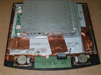
Click to zoom
Application Details
- Equipment Class
- JBP - Part 15 Class B Computing Device Peripheral
- Date of Grant
- May 28, 2002
- Application Purpose
- Original Equipment
- Date of Application
- May 28, 2002
- Equipment Note
- WBT with 15" LCD Monitor
- Company
- Gempack Co., Ltd.
- Country
- South Korea
Documents & Files
Document Text
Text extracted from the exhibit documents filed with the FCC. Open a document above to read the original.
Users Manual
’ Gempack Co.,Ltd Preface Purpose The purpose of this manual is to provide installation and operation information for the TeleCLIENT™ Windows®-Based Terminal. Audience This manual is intended for both authorized system administrators and users who have experience with networking products and Windows-based terminals. It is assumed that the personnel using this document have the appropriate background and knowledge to use the TeleCLIENT. How To Use This Manual This manual is designed to help you locate information quickly and easily. Each chapter contains the following information: Preface Provides equipment compliance, warranty and license agreement information. Chapter 1 Introduction Chapter 2 Hardware Installation Chapter 3 Operation Appendix System specifications and warranty information. Warning: The procedures described in this document are intended for authorized users only. Unauthorized personnel performing these procedures can affect the product's warranty status. European Telecom Statement The TeleCLIENT is intended for connection to a Network Centric System. DO NOT connect the TeleCLIENT to the Telecom System. ENERGY STAR® As an ENERGY STAR Partner, TeleVideo, Inc. has determined that this product meets the ENERGY STAR guidelines for energy efficiency. ENERGY STAR is a U.S. registered mark. TeleVideo, Inc. Software License Agreement PLEASE CAREFULLY READ THE FOLLOWING TERMS AND CONDITIONS BEFORE USING THIS SOFTWARE. USING THIS SOFTWARE INDICATES YOUR ACCEPTANCE OF THE FOLLOWING TERMS AND CONDITIONS. Grant You may use the TeleCLIENT Connection Manager in conjunction with the TeleCLIENT as provided. You may transfer ownership of the Equipment, including the right to transfer the Software to another party so long as that party agrees to accept these terms and conditions. YOU MAY NOT COPY, MODIFY, TRANSLATE OR TRANSFER THE SOFTWARE, OR MODIFICATION THEREOF, IN WHOLE OR IN PART, EXCEPT AS EXPRESSLY PROVIDED FOR IN THIS LICENSE. YOU MAY NOT DECOMPILE, REVERSE ENGINEER, OR OTHERWISE DECODE OR ALTER THE SOFTWARE PROVIDED WITH THIS EQUIPMENT. Limit of Liability UNDER NO CIRCUMSTANCES SHALL TELEVIDEO, INC. BE LIABLE FOR LOSS OF DATA, COSTS, OR ANY INCIDENTAL OR CONSEQUENTIAL DAMAGES, HOWEVER CAUSED AND ON ANY THEORY OF LIABILITY. THESE LIMITATIONS SHALL APPLY EVEN IF TELEVIDEO, INC. OR ITS RESELLER HAS BEEN ADVISED OF THE POSSIBILITY OF SUCH DAMAGES, AND NOTWITHSTANDING ANY FAILURE OF ESSENTIAL PURPOSE OF ANY LIMITED REMEDY PROVIDED HEREIN. WHEN USING THIS PRODUCT, YOU AGREE THAT THESE ARE THE ONLY APPLICABLE TERMS OF AGREEMENT BETWEEN US COVERING THE SOFTWARE. U.S. Government Restricted Rights This software is provided with RESTRICTED RIGHTS. Use, duplication or disclosure by the Government is subject to restrictions as set forth in subparagraph (c)(1)(ii) of the Rights in Technological Data and computer software clause at DFARS 252.227-7013 or in subparagraphs (c)(1) and (2) of the Commercial Computer Software-Restricted Rights at 8 C.F.R. 52-227-19 as applicable. Contractor/Licensor is TeleVideo, Inc. Declaration of Conformity Statement of Limited Warranty Scope of Limited Warranty TeleVideo, Inc. (TeleVideo) warrants to Buyer that its products, except software, will be free from defects in materials and workmanship for 365 days from the date of purchase. TeleVideo's obligation under this warranty will be limited to repairing or replacing, at TeleVideo's option, the parts of the products which prove defective in material or workmanship, provided that Buyer gives TeleVideo prompt notice of any defect and satisfactory proof thereof. Exclusions This limited warranty does not cover losses or damages which occur in shipment to or from Buyer, nor due to (1) improper installation or maintenance, misuse, neglect or any cause other than ordinary commercial or industrial application, or (2) adjustment, repair, or modification by anyone other than TeleVideo's authorized agent, or (3) improper environment, excessive or inadequate heating or air-conditioning and electrical power failures, surges, or other irregularities, or (4) any statements made about TeleVideo's products by sales representatives, dealers, distributors or agents, unless confirmed in writing by a TeleVideo officer. Equipment purchased must be in a new, sealed condition upon delivery to the end user in order to qualify for TeleVideo’s limited warranty. The foregoing TeleVideo limited warranty is in lieu of all other warranties, whether oral, written, expressed, implied, or statutory. Implied warranties of merchantability and fitness for a particular purpose will not apply. ’ FCC NOTICE THIS DEVICE COMPLIES WITH PART 15 OF THE FCC RULES. OPERATION IS SUBJECT TO THE FOLLOWING TWO CONDITIONS: (1) THIS DEVICE MAY NOT CAUSE HARMFUL INTERFERENCE, AND (2) THIS DEVICE MUST ACCEPT ANY INTERFERENCE RECEIVED, INCLUDING INTERFERENCE THAT MAY CAUSE UNDERSIRED OPERATION. This equipment has been tested and found to comply with the limits for a Class B digital device, pursuant to part 15 of the FCC Rules. These limits are designed to provide reasonable protection against harmful interference in a residential installation. This equipment generates, uses and can radiate radio frequency energy and, if not installed and used in accordance with the instructions, may cause harmful interference to radio communication. However, there is no guarantee that interference will not occur in a particular installation. If this equipment does cause harmful interference to radio or television reception, which can be determined by turning the equipment off and on, the user is encouraged to try to correct the interference by one or more of the following measures : - Reorient or relocate the receiving antenna. - Increase the separation between the equipment and receiver. - Connect the equipment into an outlet on a oircuit difference from that to which the receiver is connected. - Consult the dealer of an experienced radio/TV technician for help. NOTE : This unit was t…
Text truncated - open the document above for the full version.
Block Diagram
Report Number: DAC02-K0278 Appendix B - Block Diagram/Schematics
External Photos
Report Number: DAC02-K0278 Appendix D - EUT Photographs Report Number: DAC02-K0166 Appendix D - EUT Photographs
ID Label/Location Info
Report Number: DAC02-K0278 Appendix A - Sample Label Labeling Requirements per section 2.925&15.19 The label shown shall be permanently affixed at a conspicuous location on the device and be readily visible to the user at the time of purchase. Gempack MODEL. TC7380 Serial No. VOLTAGE 100-240 VAC at 50-60Hz CURRENT 4.58A FCC ID : PFMTC7380 Gempack Co.,Ltd WARNING MADE IN KOREA Label Location : Rear Side Report Number: DAC02-K0166 [Photograph of the physical location of the label ]
Internal Photos
Appendix E –EUT Part Photographs Part Photographs of EUT Report Number: DAC02-K0278 Part Photographs of EUT – Inside Report Number: DAC02-K0278 Part Photographs of EUT – High Voltage Report Number: DAC02-K0278 Part Photographs of EUT – Main Board Report Number: DAC02-K0278 Part Photographs of EUT – Panel Board.
Test Report
DASTEK EMC Lab 204, Chuge-Ri, Yangji-Myeon, Yongin -Shi, Kyunggi-Do, Korea Tel : 82-31-335-9341 Fax : 82-31-335-9343 FCC Part 15 Class B APPLICANT : Gempack Co.,Ltd. EUT Type : WBT with 15-inch LCD Monitor Model Name : TC7380 Serial No : N/A Manufacturer Name : Gempack Co.,Ltd. Address & Country : No.324-18, Dangjung-Dong, Kunpo-Shi Kyunggi-Do, Korea. Rule Part(s): : FCC 15 Subpart B Equipment Class : Class B This device has been shown to be capable of compliance with the applicable technical standard as indicated in the measurement report and was tested in accordance with the measurement procedures specified in ANSI C63.4-1992 with the following remarks (Note codes): (#37) I attest to the accuracy of data and all measurements reported herein were performed by me or were made under my supervision and are correct to the best of my knowledge and belief. I assume full responsibility for the completeness of these measurements and vouch for the qualifications of all persons taking them. Report No: DAC02-K0278 Issued Date : April 30, 2002 In-Young, Chung. Chang-Hun, Lee Manager EMC Dept Test Engineer Report Number: DAC02-K0278 Page 2 of 21 Table of Contents Scope 3 Introduction (Site Description) 4 Product Information 5 Description of Test (Radiated & Conducted) 6-7 List of Support Equipment 8 Test Result(Radiated & Conducted) 9-10 Test Data (Radiated & Conducted) 11-12 Sample Calculations 13 List of Test Equipment 14 Appendix A - Labeling Requirements 15 Appendix B - Block Diagram / Schematics 16 Appendix C - Photographs of Test Set-up (Line Conducted and Radiated Test Pictures) 17-18 Appendix D - EUT Photographs 19-20 Appendix E – User’s Manual 21 Report Number: DAC02-K0278 Page 3 of 21 Scope Measurement and determination of electromagnetic emissions (EMI) of radio frequency devices including intentional and/or unintentional radiators for compliance with the technical rules and regulations of the Federal Communications Commission. Tae-Woo Company Name : Gempack Co.,Ltd. No.324-18, Dangjung-Dong, Kunpo-Shi Kyunggi-Do, Korea. Attention: : ng, Yoon FCC ID: : PFMTC7380 Class: : Class B EUT Type : WBT with 15-inch LCD Monitor Model Name : TC7380 Trade Name : Gempack Co.,Ltd. Rule Part(s) : FCC Part 15 Subpart B Test Procedure : ANSI C-63.4 (1992) Date of Test(s) : April 12, 2002 Place of Tests : Dastek EMC Lab, in Korea. Test Report No : DAC02-K0278 Report Number: DAC02-K0278 Page 4 of 21 Introduction These measurement tests were conducted at Dastek EMC Laboratory facility in Korea. The site address is 204 Chege-Ri, Yangji-Myeon, Yongin-City, Kunggi-Do, Korea. Dastek EMC Laboratory is a company that has started the July of 1981, for manufacturing of EMI noise filters and EMI Test and diverging service. The area of test site is located at 54 Kilometers (33miles) southeast from seoul International Airport, 42 Kilometers (26miles) south-southeast from central seoul where ambient radio signal conditions are quiet and a favorable area to measure the radio frequency interference on open field test site for the computing devices manufacturers. The detailed description of the measurement facility was found to be in compliance with the requirements of section 2.948 according to ANSI C63.4 on November 02, 2000(Registration Number:90547). Report Number: DAC02-K0278 Page 5 of 21 Product Information Equipment Description The Equipment under Test (EUT) is the WBT with 15-inch LCD Monitor of Gempack Co.,Ltd. Model Name: TC7380 Serial Number : N/A 1. EUT Specification. Hardware Description CPU National Semiconductor Geode GX1™ 300MHz processor RAM Memory 32MB RAM standard Expandable to 128MB Flash Memory 8MB flash disk Flash upgrade utility via Ethernet Graphics Subsystem National Semiconductor XpressGRAPHICS™, Cx5530 Audio Support National Semiconductor XpressAUDIO™ Full 16-bit stereo FM synthesis Built-in speaker system Audio Out–Microphone in Resolution Resolution of 1024x768 16 to 65K colors Supports all VESA monitors Networking Protocols 10/100BaseT Ethernet, RJ45 TCP/IP with DNS, DHCP and PPP Load balancing supported by Citrix ICA Remote modem dial up with Citrix ICA Communication Protocols Microsoft RDP Citrix ICA Parallel Port One parallel port Serial Port One serial port USB Ports Two USB ports Audio Ports Audio out Microphone in Keyboard and Mouse Ports Keyboard and mouse ports (PS/2 keyboard and mouse included) Report Number: DAC02-K0278 Page 6 of 21 Description of Tests Conducted Emissions The line conducted facility is located inside a 4.6(m)x6.5(m)x2.5(m) shielded room. A wooden table 80cm high is located on one side of the shielded room; desktop EUTs are placed on top of this table. The rear of the EUT is placed a minimum of 40cm from the shielded room wall. The side of the EUT is 1m from the LISN, which is bonded to the shielded room wall Via a 1-foot wide bonding strap. The LISN is isolated from the other filtered power via an additional filter to ensure that RFI from the auxiliary instrumentation (scopes, etc.) does not influence the readings. The excess power cord from the EUT is folded back and forth to form a 30-40cm non-inductive bundle. All interconnecting cables more than 1 meter were shortened by non-inductive bundling (serpentine fashion) to a 1 meter length. Sufficient time for the EUT, support equipment, and test equipment was allowed in Order for them to warm up to their normal operating condition. The RF output of the LISN was connected to the spectrum analyzer to determine the frequency producing the maximum EMI from the EUT. The spectrum was scanned from 450KHz to 30MHz with 20 msec sweep time. The frequency producing the maximum level was reexamined using Quasi-Peak adapter. The detector function was set to CISPR quasi-peak mode. The bandwidth of the receiver was set to 9KHz. The EUT, support equipment, and interconnecting cables were arranged and manip- ulated to maximize each EMI emission. Each emission was maximized by: switchi…
Text truncated - open the document above for the full version.
Test Setup Photos
Report Number: DAC02-K0278 Appendix C - Test Photographs These Conducted Test Pictures shows the worst-case configuration and cable placement. [Conducted Emission Test Picture] Report Number: DAC02-K0278 These Radiated Test Pictures shows the worst-case configuration and cable placement. [Radiated Emission Test Picture]
Contact Information
Applicant
Tae-Woong Yoon(General Manager)
Test Firm
Dastek Co., Ltd.S. Hwang
Technical Specifications
| # | Rule Parts | Frequency Range | Power Output |
|---|---|---|---|
| 1 | 15B | - | - |
Other Applications from Gempack Co., Ltd.
PFMTC7530
Aug 19, 200315" Web Base Terminal
Equipment Class
JBP - Part 15 Class B Computing Device Peripheral
PFMTC7730
Jul 20, 200317" Web Base Terminal
Equipment Class
JBP - Part 15 Class B Computing Device PeripheralPFMTC7370
Jun 25, 2001WBT with 15-inch LCD Monitor
Equipment Class
JBC - Part 15 Class B Computing Device/Personal ComputerPFMGPM-151
Jan 09, 200115-inch LCD Monitor
Equipment Class
JBP - Part 15 Class B Computing Device Peripheral