PFO018-1Mini-Transmitter
Trine Access Technology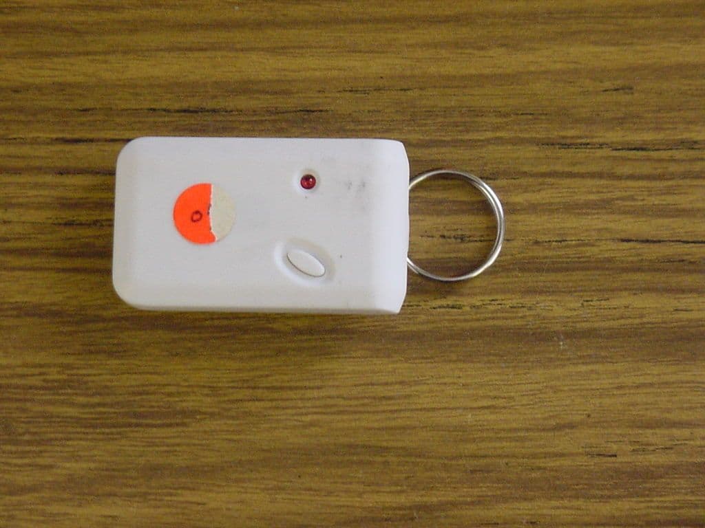
Click to zoom
Application Details
- Equipment Class
- DSC - Part 15 Security/Remote Control Transmitter
- Date of Grant
- Feb 08, 2001
- Application Purpose
- Original Equipment
- Date of Application
- Jan 04, 2001
- Equipment Note
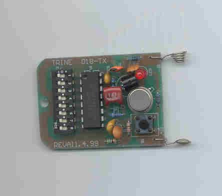
- Mini-Transmitter
- Frequency Range
- 318.00000000 - 318.00000000
- Company
- Trine Access Technology
- Country
- United States
Documents & Files
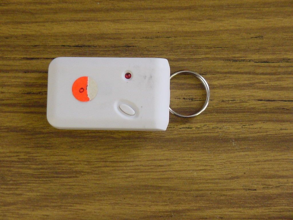
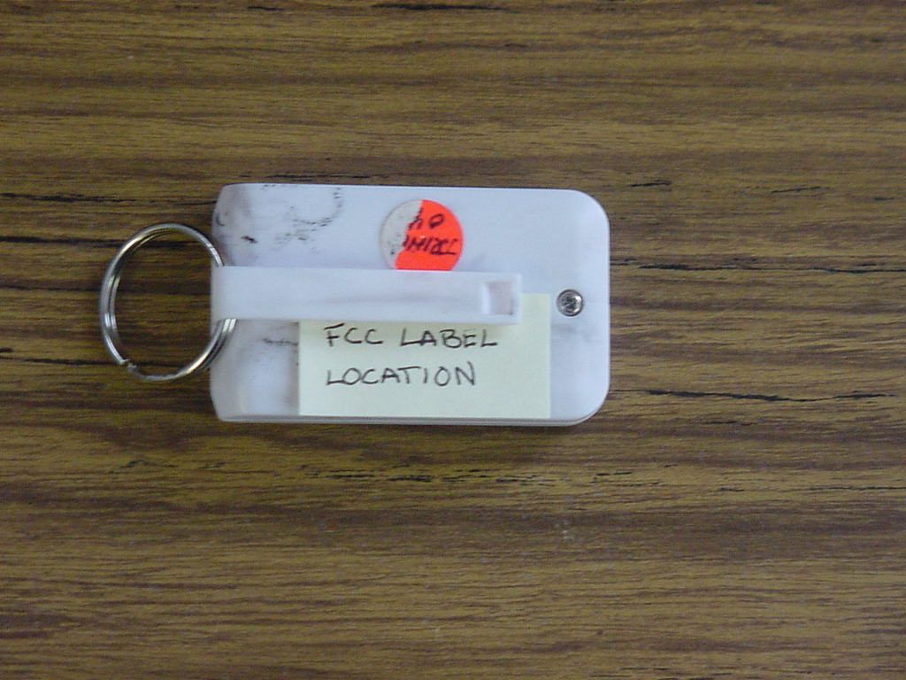
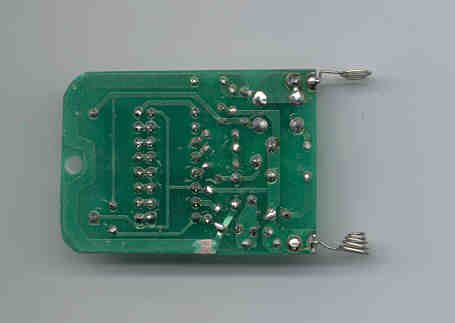
Document Text
Text extracted from the exhibit documents filed with the FCC. Open a document above to read the original.
Users Manual
MODEL 017TDC Wireless Remote Receiver/Controller FEATURES - 318 mhz Frequency - 2-30 Second Timer Delay - 3 amp Normally Open and Normally Closed. Wet Contacts rated at 12-24 volts AC/DC - 1 Amp Auxiliary Normally Open & Normally Closed. Dry Contacts rated at 6-24 volts AC/DC - Built in Monopole Antenna, - Ceramic tuned resennator - Superheterodyne receiver-low radiant - 6561 Securiy Codes APPLICATIONS: The 017TDC Controller can be used to operate low voltage devices from a remote location by means of a hand- held wireless transmitter model (018- 1). This eliminates the need to run wire from the load (electric strike, magnet, bolt, etc.) and transformer back to a switch in order to activate it. DOOR STEPDOWN TRANSFORMER 017TDC CONTROLLER STRIKE/MAGNET RECEPTIONIST RECEPTIONIST CAN BE ANYWHERE TOTAL WIRE USED: 20 FEET. INSTALLS IN HALF THE TIME The receiver has a voltage operating range of 12V to 24V, AC or DC (wet). When using a DC power source it’s important to NOT cross the (+) and (-) leads. Each receiver is clearly marked for the power in and power out terminals. The auxiliary dry form “C” contacts are rated 6-24 volts AC or DC at 1 amp - with a hermetically sealed relay. The 017TDC has a built-in time delay feature with a range of 2-30 seconds. This is used to time how long you want the relay to remian open or closed. This can be adjusted by sim- ply turning the knob which is located next to the dip switch. GENERAL INFORMATION: The remote controlled receiver is acti- vated by an RF (radio frequency) sig- nal. This signal is generated from a handheld wireless transmitter model (018-1), which is portable. When used in structures that have a high content of metal, the range will be reduced from its established 150 feet (line of sight). The receiver may be placed in a ceiling or mounted on the wall as long as the wire antenna is not obstructed or laid against any metal surface. The white antenna wire should be kept exposed. INSTALLATION: Your 017TDC receiver is equipped with a dip switch that offers 6561 dif- ferent codes to reduce interference from other wireless devices. In the event of a false activation of the receiver by another device, the codes can be changed thereby eliminating the false trigger. Simply remove the cover on the unit to expose the switches. The diagram illustrates the eight (3) position dip switch. It is not recommended that all of the switches are left in the same posi- tion. It is important to remember that the dip switch setting in the o17TDC must match the setting in the model 018-1 transmitter. With the dip switches on both the receiver and transmitter matching, the installation is ready to begin. C 2000 (1)(2)(3)(4) (5) Instruction Manual 017TDC Instructions.qxd 12/12/00 7:59 AM Page 1 ELECTRIC STRIKE NORMALLY OPEN CIRCUIT USED STAND ALONE SELF POWER DEVICE NORMALLY CLOSED OR NORMALLY OPEN DRY CIRCUIT USED POWER IN 1 - POSITIVE + 2 - NEGATIVE - POWER OUT 3 - POWER - 4 - NORMALLY OPEN + POWER IN 1 - POSITIVE + 2 - NEGATIVE - POWER LOOP 6 - NORMALLY OPEN + 7 - COMMON - 8 - NORMALLY CLOSED+ (NOTE: SELECT ONE CONTACT) The following diagrams show the cor- rect wiring required for an electric strike (normally open contact) and an electro magnetic lock (normally closed). This is simply an illustration and its important to remember that devices other than the ones illustrat- ed can be used. 017TDC CONTACT TERMINAL MARKINGS FAIL SAFE ELECTRIC STRIKE OR ELECTRO MAGNETIC LOCK NORMALLY CLOSED CIRCUIT USED POWER IN 1 - POSITIVE + 2 - NEGATIVE - POWER OUT 3 - POWER - 5 - NORMALLY CLOSED + (6)(7)(8(9) 12-24 AC OR DC Transformer is required 1440 FERRIS PLACE BRONX, NY 10461 PH: 718-829-2332 FAX: 718-829-6405 www.trineonline.com Section 15.21 Information to User The users manual or instruction manual for an intentional or unintentional radiator shall caution the user that changes or modifications not expressly approved by the party responsible for compliance could void the user’s authority to operate the equip- ment. 017TDC Instructions.qxd 12/12/00 7:59 AM Page 2
Cover Letter(s)
June 16, 2000 Federal Communications Commission Equipment Authorization Division Applications processing Branch 7435 Oakland Mills Road Columbia, MD 21046 Ref: Request for Confidentiality Dear Sir, We at Trine Access Technology request that the schematic diagram, part list and block diagram, submitted with this Certification Application, be withheld from public disclosure as per Section .459 of the FCC rules. This request is made under provision of Section 0.457 (d) of the FCC Rules and Section 0.552(b)(4) of the Freedom of Information Act. Disclosure of this electronic design information would place Trine Access Technology at a competitive disadvantage. Thank You. Sincerely; Gary Ferguson Technical Manager 1440 FERRIS PLACE BRONX, NY 10461-3699
Cover Letter(s)
Tuesday, June 13, 2000 Retlif Testing Laboratories 101 New Boston Road Goffstown, NH 03045 RE: Trine Access Technology (018-1 FCC Filing) Dear Mr. Scott Wentworth, This letter is in request of Retlif, as agent, to perform testing and FCC filing for USA/Canada, on Trine Access Technology, product 018-1 wireless transmitter. Gary Ferguson Technical Manager 1440 FERRIS PLACE BRONX, NY 10461-3699
ID Label/Location Info
TRINE ACCESS TECHNOLOGY CANADA # MODEL # 018-1 FCC ID: PFO018-1 This device complies with part 15 of the FCC Rules. Operation is subject to the following two conditions: (1) This device may not cause harmful interference, and (2) This device must accept any interference received including intererence that may cause undesired operation. MADE IN CHINA
Test Report
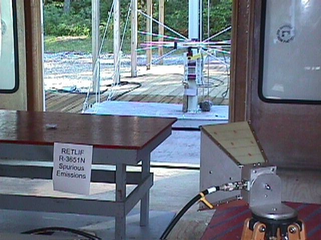
January 5, 2001 Federal Communications Commission Equipment Approval Services PO Box 358315 Pittsburgh, PA 15251-5315 Dear Sir/Madam: Enclosed you will find an application for Certification of a Wireless Security System 318MHz RF Transmitter, Model 018-1, Serial No. n/a, FCC ID: PFO018-1. Certification is requested to the requirements of Part 15, Subpart C of the Commission’s rules. This application is being filed by Retlif Testing Laboratories on behalf of Trine Access Technology The applicable Certification Filing Fee and 731 Form have been submitted. I trust that you will find the enclosed application to be complete; however, should you have any questions or require any additional information, please feel free to contact us. Very truly yours, RETLIF TESTING LABORATORIES Scott Wentworth Manager Enc. (as stated) Test Report No. R-3651N1 FCC ID: PFO018-1 APPLICANT Trine Access Technology 1440 Ferris Place Bronx, NY 10461-3699 MANUFACTURER SAME TEST SPECIFICATION: FCC Rules and Regulations Part 15, Subpart C, Para. 15.231 TEST PROCEDURE: ANSI C63.4:1992 TEST SAMPLE DESCRIPTION BRANDNAME: Trine Access Technology MODEL: 018-1 TYPE: Wireless Security System 318MHz RF Transmitter POWER REQUIREMENTS:12VDC Battery FREQUENCY OF OPERATION: 318MHz FCC ID: PFO018-1 APPLICABLE RULE SECTION: Part 15, Subpart C, Section 15.201 General Requirements and 15.231 Alternative Requirements TESTS PERFORMED Radiated Emissions, Scan to 10 th Harmonic Occupied Bandwidth, 0.25% of Fundamental Frequency Duty Cycle Determination TEST SAMPLE OPERATION The EUT is battery operated and was tested with newly installed batteries. For testing purposes only, the EUT was configured to operate continuously, which required peak detector readings combined with the duty cycle factor to produce the required average reading. Normal operation of the EUT complies with the parameters required in Part 15, Subpart C, Section 15.231. Test Report No. R-3651N1 FCC ID: PFO018-1 TEST SAMPLE / TEST PROGRAM CThe transmitter is manually operated. CThe transmitter does not perform periodic transmissions at regularly predetermined intervals. CThe device can be employed for RC purposes involving security. CThe fundamental field strength at 318MHz did not exceed 6167μV/M (Average) at a test distance of 3 meters. In addition, the requirements of section 15.35 for averaging pulsed emissions and for limiting peak emissions were met. CThe field strength of harmonic and spurious emissions did not exceed 616.7μV/M as applicable. Except the restricted bands 501μV/M. CThe device operates at a frequency range of 318MHz. The bandwidth of emissions did not exceed 0.25% of the operating frequency and was determined as follows: Fundamental Frequency=318MHz 0.25% of Center Frequency=.795MHz .795 divided by 2=.3975MHz Bandwidth Range=Fundamental Frequency + and - 0.3975MHz 318MHz - .3975MHz=317.6025MHz 318MHz + .3975MHz=318.3975MHz Bandwidth Range=317.6025MHz - 318.3975MHz CRadiated Emissions from the EUT were measured in all three axis. Worst case emissions were found with the EUT in the vertical upright position with the measurement antenna polarized horizontally. Test Report No. R-3651N1 FCC ID: PFO018-1 TEST SAMPLE / TEST PROGRAM (continued) DETERMINATION OF FIELD STRENGTH LIMITS The field strength limits shown below were calculated as instructed in Section 15.231. Fundamental Frequency: 318MHz Where F is the frequency in MHz, the formula for calculating the maximum permitted fundamental field strength for the band 260-470MHz, μV/m at 3 meters is as follows: 41.6667(F) - 7083.3333 =Field Strength Limit (μV/m) 41.6667 x 318=13250 3250 - 7083.3333=6166.66 Field Strength Limit=6167 μV/m The maximum permitted unwanted emission level is 20dB below the maximum permitted fundamental level. DETERMINATION OF DUTY CYCLE The transmitter controls were adjusted to maximize the transmitted duty cycle. The analyzer was set for a frequency span of 0Hz. The sweep time was then adjusted in order to display one full pulse train. The transmitter on time was then summed and compared to the time for one full cycle in order to obtain the duty cycle. Transmitter On Time=39.1 milliseconds (maximum) Transmitter Cycle Time=66.75 milliseconds Transmitter Duty Cycle=58.58 % On Time divided by Cycle Time=Duty Cycle Factor 39.1 divided by 66.75=0.585 0.585 converted to dB (LOG 10 .585)20=-4.65dB Duty Cycle Factor=-4.65dB Duty Cycle Factor Determination Plots are included with this application as a separate attachment. Test Report No. R-3651N1 FCC ID: PFO018-1 TEST SAMPLE / TEST PROGRAM (continued) SPECTRUM ANALYZER Due to the nature of the emissions being measured, care was taken to ensure that the resolution bandwidth of the spectrum analyzer was adequate to provide accurate measurements. Test Report No. R-3651N1 FCC ID: PFO018-1 EQUIPMENT LIST Radiated Emissions EN Type Manufacturer Description Model No. Cal Date Due Date 3258 Double Ridge Guide EMCO 1 - 18 GHz 3115 4/6/00 4/6/01 4202 Biconilog EMCO 26 MHz - 2 GHz 3142 7/10/00 7/10/01 4895 Spectrum Analyzer Hewlett Packard 9kHz - 22GHz 8593EM 2/17/00 2/17/01 EQUIPMENT LIST Occupied Bandwidth EN Type Manufacturer Description Model No. Cal Date Due Date 4202 Biconilog EMCO 26 MHz - 2 GHz 3142 07/10/2000 07/10/2001 4895 Spectrum Analyzer Hewlett Packard 9kHz - 22GHz 8593EM 02/17/2000 02/17/2001
Test Report
EQUIPMENT LIST Occupied Bandwidth ENTypeManufacture rDe scriptionMode l No.Cal Date Due Date 4202BiconilogEMCO26 MHz - 2 GHz314207/10/200007/10/2001 4895Spectrum AnalyzerHewlett Packard9kHz - 22GHz8593EM02/17/200002/17/2001
Test Report
EQUIPMENT LIST Radiated Emissions ENTypeManufacture rDe scriptionMode l No.Cal Date Due Date 3258Double Ridge GuideEMCO1 - 18 GHz31154/6/004/6/01 4202BiconilogEMCO26 MHz - 2 GHz31427/10/007/10/01 4895Spectrum AnalyzerHewlett Packard9kHz - 22GHz8593EM2/17/002/17/01
Test Report
Test AxisMeterCorrectionDuty CycleCorrected ConvertedLimit Frequency PolarizationReadingFactorFactorReadingsReadingat 3m MHzX,Y,Z H/VdBuVdBdBdBuV/muV/muV/m 318.0X V45.3122.80-68.112543.9061667.00 318.0 Y V45.8022.80-68.602691.5361667.00 318.0Z V36.0722.80-58.87878.0161667.00 318.0X H47.5022.80-70.303273.4161667.00 318.0Y H43.9222.80-66.722167.7061667.00 318.0Z H48.6822.80-71.483749.7361667.00 318.0X V45.3122.80-4.6563.461489.366167.00 318.0 Y V45.8022.80-4.6563.951575.806167.00 318.0Z V36.0722.80-4.6554.22514.046167.00 318.0X H47.5022.80-4.6565.651916.466167.00 318.0Y H43.9222.80-4.6562.071269.116167.00 318.0Z H48.6822.80-4.6566.832195.336167.00 636.0 Y V26.1432.20-4.6553.69483.62616.70 636.0X H24.3332.20-4.6551.88392.64616.70 636.0Y H22.9732.20-4.6550.52335.74616.70 636.0Z H23.0932.20-4.6550.64340.41616.70 l------- 3200------- The frequency range from 30 MHz to 3.2 GHz was scanned, all EUT emissions within 10 dB of the specified limit that were observed are listed on this data sheet. RETLIF TESTING LABORATORIES TABULAR DATA SHEET TEST METHOD: Radiated Emissions 30 MHz to 3.2 GHz PARAGRAPH: 15.231 TEST SPECIFICATION: FCC Part 15, Subpart C Frequency Tested: 318 MHz OPERATING MODE: Continuously Transmitting. NOTES: Detector Function: Peak Test Distance: 3Meters. Internal dip switches in " - " position Radiated Emissions Limit Test (Per 15.231) DATA SHEET 1 OF 1 R-3651N1 CUSTOMER: Trine Access Technology JOB NO: R-3651N1 MODEL NO: 018-1 SERIAL NO: n/a TEST SAMPLE: Wireless Security System 318 MHz RF Transmitter TECHNICIAN: M. Hippert DATE: 10-4-00 Peak Emission Limit Test (Per 15.35(b))
Contact Information
Applicant
Ferdinand Orbeta(Engineering Manager)
Technical Contact
Retlif Testing LaboratoriesJohn Monahan
[email protected]603-497-4600
101 New Boston Road · Goffstown, New Hampshire · United States
Non-Technical Contact
Retlif Testing LaboratoriesScott Wentworth
[email protected]603-497-4600
Test Firm
Retlif Testing LaboratoriesScott Wentworth
Technical Specifications
| # | Rule Parts | Frequency Range | Power Output |
|---|---|---|---|
| 1 | 15C | 318 MHz - 318 MHz | - |