PFRFXRD-1717NAWFlat Panel Detector
Vieworks Co., Ltd.
Click to zoom
Application Details
- Equipment Class
- DTS - Digital Transmission System
- Date of Grant
- Apr 29, 2015
- Application Purpose
- Original Equipment
- Date of Application
- Apr 29, 2015
- Equipment Note
- Flat Panel Detector
- Frequency Range
- 5745.00000000 - 5825.00000000
- Company
- Vieworks Co., Ltd.
- Country
- South Korea
Documents & Files
Document Text
Text extracted from the exhibit documents filed with the FCC. Open a document above to read the original.
Users Manual
VIVIX-S 1717N User Manual © Vieworks. 2015 All rights reserved. Under copyright laws, this manual should not be reproduced, in whole or in part, without the written permission of Vieworks. Rev.1.0 Page 2 of 151 VW40-153-006 VIVIX-S 1717N User Manual Contents 1. Instruction ......................................................................................................................................... 8 1.1 Document Guide ..................................................................................................................................... 9 1.1.1 Caution Information ..................................................................................................................................................... 9 1.1.2 Target ................................................................................................................................................................................... 9 1.1.3 Symbols .............................................................................................................................................................................. 9 1.1.4 Notations .........................................................................................................................................................................10 1.1.5 Contact Department ...................................................................................................................................................10 1.2 Product Use Guide ................................................................................................................................ 11 1.2.1 Product Usage ...............................................................................................................................................................11 1.2.2 Disclaimer ........................................................................................................................................................................11 1.2.3 Product Disposal ..........................................................................................................................................................12 1.2.4 Trademarks ......................................................................................................................................................................12 1.3 Safety Instruction .................................................................................................................................. 13 1.3.1 Management and Authority ...................................................................................................................................13 1.3.2 Power Supply .................................................................................................................................................................13 1.3.3 Handling ...........................................................................................................................................................................14 1.3.4 Battery Pack and Charger ........................................................................................................................................15 1.3.5 Environment of Use ....................................................................................................................................................16 1.3.6 Problem Management ...............................................................................................................................................17 1.3.7 Maintenance and Inspection ..................................................................................................................................17 1.4 Product Usage Guide ............................................................................................................................ 18 1.4.1 Calibration .......................................................................................................................................................................18 1.4.2 Length Measurement .................................................................................................................................................18 1.4.3 Left/Right Marker.........................................................................................................................................................18 1.4.4 Image Backup ................................................................................................................................................................18 1.4.5 Use Limitations .............................................................................................................................................................19 1.4.6 Disposal ............................................................................................................................................................................19 1.4.7 Pediatric Application ..................................................................................................................................................19 1.4.8 Before Exposure ............................................................................................................................................................19 1.4.9 During Exposure ...........................................................................................................................................................20 1.4.10 Operating and Storage Environment .................................................................................................................20 1.4.11 Others................................................................................................................................................................................20 2. Product .............................................................................................…
Text truncated - open the document above for the full version.
Users Manual
Rev.1.0 Page 71 of 151 VW40-153-006 VIVIX-S 1717N User Manual 4.2.4 Checking Status LED of Detector Power LED The power LED indicates the power status information which is permitted to the detector in green. The power LED lights up when the power is permitted normally. If the detector is connected with a tether interface, the power LED lights up when power is permitted to SCU because the detector is supplied power from SCU. Active LED The active LED indicates status information about the possibility that the detector can be used normally or not in orange. The active LED is blinking when the detector is completed to boot up normally. The Power LED is blinking when the detector turns to sleep mode. The active LED is blinking when the wireless communication is being initialized. Data LED The data LED indicates status information of data processing in blue. The data LED lights up when the detector is available to make data communication. The data LED is blinking while the detector transmits or saves data. Detector AP LED The AP LED lights up in blue when the detector AP is on. The AP LED is blinking in blue when the detector switches the AP status. The AP LED is blinking in orange while the detector is synchronizing the wireless settings. The communication status of detector is indicated when the detector AP is off. Wirelss communication: Green LED at the 3 rd level or higher / Orange LED under 2 nd level. Wired communication: Green LED in case of 1Gbps / Orange LED in case of 100Mbps connection. Summary List of Detector Status LED Information Power LED Status LED Data LED In process of booting after the power permission Blink OFF OFF Booting completed (Abnormal) ON - - Booting completed (Normal) ON ON OFF Ready for communication ON ON ON Sleep Mode ON Blink OFF In process of wireless initialization ON Blink OFF Data Communication (Send or Store) ON ON Blink Power OFF OFF OFF OFF Rev.1.0 Page 72 of 151 VW40-153-006 VIVIX-S 1717N User Manual Summary list of the Detector AP LED Information Detector AP LED Detector AP OFF (Communication status: Good) Wireelss communication: 3 rd level or higher Wired communication: 1000Mbps ON Detector AP OFF (Communication status: Normal) Wireelss communication: Under 2 nd level Wired communication: 100Mbps ON Detector AP ON ON Switching the status of detector AP Blink The wireless setting is being synchronized Blink Power OFF OFF If the LED blinks abnormally, refer to <8 Troubleshooting> to check if communication or system error is occurred. Rev.1.0 Page 73 of 151 VW40-153-006 VIVIX-S 1717N User Manual 4.3 Software Installation This section gives information about how to install the software on the workstation (PC) and how to configure the environment for software operation and communication. Check suitability of acquiring, processing and adjusting of images by referring to the recommended workstation specifications before the software installation. 4.3.1 Software Classification Vieworks provides clients who purchase our detector system with software as below. You can choose and use one of our softwares below. Software Description VXvue A program for acquiring and adjusting images developed by Vieworks. Used for VIVIX-S detectors only. Unnecessary to develop a separate viewer program. VIVIX Setup A program for setting and managing the detector and SCU. VXvue (Viewer) Software for acquiring, adjusting and managing the image. XIPL Image processing program Document VXvue Operation Manual XIPL User Manual VIVIX SDK Software development kit for VIVIX-S detector only, provided by Vieworks. You can develop your own software dedicated to VIVIX-S by using this kit. SDK Package Development package VIVIX Setup A program for acquiring, adjusting and managing the image. Document VIVIX SDK Developer Manual 4.3.2 Software Installation For a client who uses VXvue, install the VXvue program after reading VXvue Operation Manual carefully. For a client who uses VIVIX SDK, install the VIVIX Setup program after reading VIVIX SDK Developer Manual. Be sure to install the software first with reading this manual before configuring Windows environment. Apart from the detector and SCU, the software can be installed separately. Rev.1.0 Page 74 of 151 VW40-153-006 VIVIX-S 1717N User Manual 4.4 Windows Environment Setting This section gives information about configuring Windows to communicate with the detector and SCU after installing the VIVIX Setup program or Viewer. The contents in this chapter are made on the basis of Windows 7. Configuration environment can be different depending on network adaptor manufacturer or models. 4.4.1 Network Configuration Communication disruption between the detector (or SCU) and workstation occurs unless the network adaptor is proper is set properly, it may cause serious repercussion to the product and image quality. Selecting Network Adaptor 1 Click Start Control Panel Network and Internet Network and Sharing Center Change Adapter Setting. 2 Choose the networks adaptor for communicating with the detector and SCU, and then rename it. It is recommended to change the name of network adaptor to distinguish it from other connection names. Even though the name is changed, it will not affect to the operation and communication performance of the equipment. 3 Click the chosen network adaptor with the right mouse button and click Properties to display the Properties window. Rev.1.0 Page 75 of 151 VW40-153-006 VIVIX-S 1717N User Manual Setting Network Adaptor 1 Click Configure button to open the following dialog box, and then go to the Advanced tab. 2 Set Jumbo Packet to the maximum value. (Recommended value: 9014 Bytes) 3 Choose Performance Options in the list of Settings and click Properties button on the right. 4 Choose Flow Control in the list of Settings and select Rx & Tx Enabled on the Value list as shown below. Rev.1.0 Page 76 of 151 VW40-153-006 VIVIX-S 1717N Us…
Text truncated - open the document above for the full version.
Cover Letter(s)
Date: April, 10. 2015 Federal Communications Commission 7435 Oakland Mills Road Columbia MD 21046 To whom it may concern: I, the undersigned, hereby authorize KT Kang of KES Co., Ltd. and hereafter referred to as KES Co., Ltd., to act on our behalf in all manners relating to application for equipment authorization, including signing of all documents relating to these matters. Any and all acts carried out by KT Kang of KES Co., Ltd. on our behalf shall have the same effect as acts of our own. I, the undersigned, hereby certify that we are not subject to a denial of federal benefits, that includes FCC benefits, pursuant to Section 5301 of the Anti-Drug Abuse Act of 1988, 21 U.S.C. 853(a). In authorizing KES Co., Ltd. as our agent, we still recognize that we are responsible to: a) comply with the relevant provisions of the certification program; b) make all necessary arrangements for the conduct of the evaluation, including provision for examining documentation and access to all areas, records (including internal audit reports) and personnel for the purposes of evaluation (e.g. testing, inspection, assessment, surveillance, reassessment) and resolution of complaints; c) make claims regarding certification only in respect of the scope for which certification has been granted; d) do not use our product certification in such a manner as to bring the Certification Division into disrepute and not make any statement regarding our product certification which the Certification Division may consider misleading or unauthorized; e) upon suspension or cancellation of certification, discontinue use of all advertising matter that contains any reference thereto and return any certification documents as required by the Certification Division; f) use certification only to indicate the products are certified as being in conformity with specified standards; g) endeavor to ensure that no certificate or report nor any part thereof is used in a misleading manner; h) ensure that any reference to our product certification in communication media such as documents, brochures or advertising, complies with the requirements of the Certification Division; i) keep a record of all complaints made known to the us relating to the product’s compliance with requirements of the relevant standard and to make these records available to the Certification Division when requested; j) take appropriate action with respect to such complaints and any deficiencies found in products or services that affect compliance with the requirements for certification; k) document the actions taken. This authorization is valid until further written notice from the applicant. Sincerely Yours, Assistant Manager / Youjeong Kim REMARK: 1. This authorization letter will be sent along with your application when filing with the Certification Division. 2. Please follow the format and type it on company letterhead and send original to us. 3. Authorized signature must be in agreement with grantee code contact in FCC database.
Cover Letter(s)
Federal Equipm e 7435 Oa Columb April 1 0 TO WH The co m RF mod Best re g Compan Ty pe Na Title : A Communica ent Authoriz akland Mills ia, MD 210 4 0, 2015 OM IT MA Y mpany Viewo dule (FCC ID gards, ny : Viework ame : Youjeo Assistant Man AT For F ation Commis zation Divisio Road 48 Y CONCERN orks Co., Ltd D:RYK-WPE s Co., Ltd. ong Kim nager ATTESTA CC ID : ssion on, Applicati N d. Product F A-121N) do ATION PFRFXR ion Processin FXRD-1717N es not use D LETTE RD-1717 ng Branch NAW (FCC FS band. ER 7NAW ID:PFRFXRRD-1717NAWW) in the
Cover Letter(s)
Date: April 10, 2015 Federal Communications Commission Authorization and Evaluation Division Confidentiality Request regarding application for certification of FCC ID: PFRFXRD-1717NAW Pursuant to Sections 0.457 and 0.459 of the Commission’s Rules, we hereby request confidential treatment of information accompanying this application as outlined below: Exhibit Type File Name Part List CONF APPENDIX_FXRD-1717NAW_Part List.PDF Schematics Diagram(s) CONF APPENDIX_ FXRD-1717NAW _Schemetics.PDF Block diagram CONF APPENDIX_ FXRD-1717NAW _Block diagram.PDF Operation description CONF APPENDIX_ FXRD-1717NAW _Operation description.PDF The above materials contain trade secrets and proprietary information not customarily released to the public. The public disclosure of these materials may be harmful to the applicant and provide unjustified benefits to its competitors. The applicant understands that pursuant to Section 0.457 of the Rules, disclosure of this application and all accompanying documentation will not be made before the date of the Grant for this application. Sincerely, Youjeong Kim / Assistant Manager
Cover Letter(s)
4 To who m This de v No har d increase modular submitte The ra d addition Should y Sincere l Compan Ty pe Na Title : A 41-3, Burim-r m it may con vice with FC Wi-Fi mo dware design e the RF out r report(Rep ed to represe diated RF te nally. you have any ly, ny : Viework ame : Youjeo Assistant Man ro 170beon-g Tel: + ncern : C ID: PFRF X odule n changes ar tput power o port Numbe nt the compl esting items y comments s Co., Ltd. ong Kim nager Viewo gil, Dongan- +82-70-4496 XRD-1717N re made on of the modu er : FR1316 liance of FCC are tested or questions orks Co -gu, Anyang- 6-1860 / Fax: NAW integrat Brand Sparklan the modules ules. pursuan 667-01AC / C Part 15C/1 on this hos , please feel o., Ltd. -si, Gyeongg +82-31-386 tes a Wi-Fi m s, and the so nt to KDB 9 / FR131667 15E conducte st device, a free to conta . gi-do, Republ 6-8631 module : FCC ID RYK-WPEA oftware has n 996369 D01 7-01AI / FR ed RF testing and the test act me. lic of KORE A-121N not been ch 1v01r04, the R131667-01A g items of th report is s EA hanged to e original AN) are his device. submitted
Cover Letter(s)
1 도근억 보낸 사람: [email protected] 보낸 날짜: 2014년 12월 23일 화요일 오후 11:39 받는 사람: [email protected] 제목: Response to Inquiry to FCC (Tracking Number 547865) Link to F ederal C o mmunicatio ns C o mmissio n Ho me Page FCC Home | Search | RSS | Updates | E-Filing | Initiatives | Consumers | Find People Office of Engineering and Technology Office of Engineering and Technology Inquiry on 12/23/2014 : Inquiry: With reference to a X-ray detecor, we have some questions. 1. The X-ray detector does not use the side & rear surface. So, we think that the X-ray detector has to need the fornt surface. please check it. 2. For head SAR, testing of both head and body properties should be conducted using a flat phantom. please check it. FCC response on 12/23/2014 X‐Ray bucky style devices do require SAR analysis consistent with KDB Publication 447498 D01 (including simultaneous transmission considerations). Accordingly, SAR testing will be required if the test exclusion criteria outlined in Section 4.3 are not met. Please be aware that, should testing be required, a 0mm test distance should be considered for such an EUT. Specifically: 1. KDB 447498 D01 states that the test separation distance will be determined by the smallest distance between the outer surface of the devices and the user (4.1.5). In this case, a distance of 0mm is expected. In such cases, SAR testing of the EUT in direct contact with a flat phantom would be appropriate. 2 Section 4.3.1 and 4.3.2 discuss standalone and simultaneous test exclusion procedures which may be applicable to the different transmitters on the EUT. Should test exclusion be applied, a statement of justification and compliance must be included in the equipment approval, in lieu of the SAR report, to qualify for the SAR test exclusion being claim. All analysis should consider both Wi‐Fi antennas. With regard to Wi‐Fi specific testing configurations, KDB Publication 248227 D01 discusses proper channel and setup procedures. 2. SAR testing along the side of the x‐ray detector is not required so long as the there is no use case requiring a user to be within 20cm of the outer edge of the EUT. 3. Testing of both head and body properties should be conducted using a flat phantom. These parameters are outlined in KDB Publication 865664 D01. Attachment Details: X-ray detector Do not reply to this message. Please select the Reply to an Inquiry Response link from the OET Inquiry System to add any additional information pertaining to this inquiry.
External Photos
www.kes.co.kr Model No.: FXRD-1717NAW Page 1 of 2 EUT External photographs Front Rear www.kes.co.kr Model No.: FXRD-1717NAW Page 2 of 2 Edge 1 Edge 2
ID Label/Location Info
Label and Location Model No.: FXRD-1717NAW Page 1 of 1 Contains FCC ID : RYK-WPEA-121N PFRFXRD-1717NAW PFRFXRD-1717NAW Contains FCC ID : RYK-WPEA-121N
Internal Photos
www.kes.co.kr Model No.: FXRD-1717NAW Page 1 of 15 EUT Internal photographs Detector Inside Detector Inside(Metal shield removed) www.kes.co.kr Model No.: FXRD-1717NAW Page 2 of 15 Antenna Location Antenna Zoom1 www.kes.co.kr Model No.: FXRD-1717NAW Page 3 of 15 Antenna Zoom2 AED board (Top) www.kes.co.kr Model No.: FXRD-1717NAW Page 4 of 15 AED board (Bottom) BATT board(Top) www.kes.co.kr Model No.: FXRD-1717NAW Page 5 of 15 BATT board(Bottom) Control board(Top) www.kes.co.kr Model No.: FXRD-1717NAW Page 6 of 15 Control board(Bottom) Gate Board(Top) www.kes.co.kr Model No.: FXRD-1717NAW Page 7 of 15 Gate Board_Zoom 1(Top) Gate Board_Zoom 2(Top) www.kes.co.kr Model No.: FXRD-1717NAW Page 8 of 15 Gate Board(Bottom) Gate Board_Zoom 1(Bottom) www.kes.co.kr Model No.: FXRD-1717NAW Page 9 of 15 Gate Board_Zoom 2(Bottom) Signal Board(Top) www.kes.co.kr Model No.: FXRD-1717NAW Page 10 of 15 Signal Board_Zoom 1(Top) Signal Board_Zoom 2(Top) www.kes.co.kr Model No.: FXRD-1717NAW Page 11 of 15 Signal Board(Bottom) Signal Board_Zoom 1(Bottom) www.kes.co.kr Model No.: FXRD-1717NAW Page 12 of 15 Signal Board_Zoom 2(Bottom) CC30 Board (Top) www.kes.co.kr Model No.: FXRD-1717NAW Page 13 of 15 CC30 Board (Shields removed_Top) CC30 Board (Bottom) www.kes.co.kr Model No.: FXRD-1717NAW Page 14 of 15 RF Module(Top) RF Module(Bottom) www.kes.co.kr Model No.: FXRD-1717NAW Page 15 of 15 RF Module(Shields removed_Top) RF Module(shields removed_Bottom)
Operational Description
Vieworks 2012-01 Antenna PCB Dual-Band Antenna (Wi-Fi 2.4/5GHz) PRODUCT APPROVAL SHEET Version : 2.0 SuppliersCustomer WriterReviewApprovalApproved by ModelVieworks 2012-01 Dual Band PCB Antenna Part NumberAEi-2450/5500DP-C1.13[Vieworks] DescriptionDual-Band(2.4/5GHz) /PCB /I-Pex SalesRodem Microsystem D RODEM MICROSYSTEM CO., LTD. RODEM MICROSYSTEM CO., LTD.RODEM MICROSYSTEM CO., LTD. RODEM MICROSYSTEM CO., LTD. (448-808) #401, Sangsaeng B/D, 253-1, Jukjeon-ro, Suji-gu, Yongin-si, Gyeonggi-do, KOREA Office : +82-31-715-9309 | Fax : +82-505-329-9309 E-mail : [email protected]| Website :www.rodemsys.co.kr Vieworks Co., Ltd. 2 Revised History Vieworks 2012-01 Antenna - PRODUCT APPROVAL SHEET VersionPurposeDateEditor V 1.0Initial Doc2012/05/11Bae Jae-Kyun V 2.0Gain & Measurement2012/10/04Bae Jae-Kyun 3 1. SPECIFICATION MECHANICAL SPECIFICATIONS SPECREMARK TYPEFR-4 RADIATION TYPEDipole PCB CONNECTOR TYPEU.FLGOLD-PLATING CABLE1.13Φ, 300mmBLACK-Color MATERIALFR-4, 0.8T DIMENSION44 x 10 x 0.8mm OPERATING TEMPERATURE(°C)-30°~ +70° 1.1. Model : AEi–2450/5500DP-C1.13[Vieworks] 1.2. Application This specifications are specified for the Wi-Fi dual band PCB antenna. 1.3. ANTENNA conditions of use □Portable ■Stationary □Mobile □Outdoor ■Indoor □etc. ( ) 1.4. ANTENNA shape Refer to the attached drawings. 1.5. Electrical characteristics and performance Working conditions or their equivalent state must be satisfied the following. Vieworks 2012-01 Antenna - PRODUCT APPROVAL SHEET 1.6. Mechanical specifications and properties ELECTRICAL SPECIFICATIONS MODELAEi-2450/5500DP-C1.13[Vieworks] (MHz)2.4~2.5GHz / 5.2~5.8GHGz V.S.W.RLESS THAN 1 : 5.0 GAIN(dBi) - 2.4GHz2.5dBi[ Composite Gain : 4.3 dBi] GAIN(dBi) - 5.2GHz(5150~5350)1.99dBi[ Composite Gain : 4.7 dBi] GAIN(dBi) - 5.6GHz(5470~5725)2.19dBi[ Composite Gain : 5.0 dBi] Max Input Power5 [W] Input Impedance50[Ω] POLARIZATIONIsotropic 4 1.7. Other performance and properties 1.7.1 Anti-shock With combining the antenna, applying the peak to peak amplitude 1mm vibration, swept frequency to 5~55Hz at 1 minute intervals, in vertical and horizontal, left and right, forward and backward directions for 2 hours, it is measured. It should be no problems in each part. It is satisfied with the characteristics and performance of the clause 5. 1.7.2 Temperature Properties The antenna is measured after being left for 96 hours at -30°Cand 70°Crespectively. It should be no problem such as separation, modification in each part. It is satisfied with the characteristics and performance of the clause 5. 1.7.3 Humidity Properties The antenna is measured after being left for 96 hours at ambient temperature 40°C and relative humidity 90~95%. It should be no problem in appearance, on the structure in each part. It is satisfied with the characteristics and performance of the clause 5. 1.8. Measurement and Inspection It should be appropriate for specifications and requirements in this approval sheet, and also suitable for quality management regulations of our company. However, clause 7 may be omitted by agreement of the buyer. 1.9. Packaging The product has to do assembly packaging not to do movement of the boxes after doing individual packaging. 1.10. Assurance If any part of the product proves to be defective, is determined to be defective design or manufacturing, within one year of the date of purchase, it is under an obligation to repair or replace free of charge, immediately. Vieworks 2012-01 Antenna - PRODUCT APPROVAL SHEET 5 2. Measurement 2.1. Measurement Antenna installation for measuring antenna gain, radiation pattern. - Calibration frequency band : 2.4 ~ 6.0[GHz] - Radiation pattern angle step : 05° Vieworks 2012-01 Antenna - PRODUCT APPROVAL SHEET The upper side Antenna The left side Antenna 6 3.1. Radiation Pattern / The left side - 2.4GHz 3. SPEC Data Vieworks 2012-01 Antenna - PRODUCT APPROVAL SHEET 7 3.2 Radiation Pattern / The left side - 5GHz 3. SPEC Data Vieworks 2012-01 Antenna - PRODUCT APPROVAL SHEET 8 3.3. Radiation Pattern / The upper side – 2.4GHz 3. SPEC Data Vieworks 2012-01 Antenna - PRODUCT APPROVAL SHEET 9 3.4. Radiation Pattern / The upper side – 5GHz 3. SPEC Data Vieworks 2012-01 Antenna - PRODUCT APPROVAL SHEET 10 4.1. Input Impedance Matching (VSWR) 4. INPUT Impedance <4.1 Left Antenna - VSWR> <4.2 Upper Antenna - VSWR> Vieworks 2012-01 Antenna - PRODUCT APPROVAL SHEET 11 5. Antenna Dimension Vieworks 2012-01 Antenna - PRODUCT APPROVAL SHEET 12 6. Antenna Image Vieworks 2012-01 Antenna - PRODUCT APPROVAL SHEET
RF Exposure Info
KES Co., Ltd. C-3701, Simin-daero 365-40l, Dongan-gu, Anyang-si, Gyeonggi-do, 431-716, Korea Tel: +82-31-425-6200 / Fax: +82-31-424-0450 www.kes.co.kr Test report No.: KES-SR-15T0009 Page (2 ) of (26) This report shall not be reproduced except in full, without the written approval of KES Co., Ltd. The test results in the report only apply to the tested sample. KES-P-5101-14 Rev. 1 KES A4 Revision history Revision Date of issue Test report No. Description - 2015.04.17 KES-SR-15T0009Initial KES Co., Ltd. C-3701, Simin-daero 365-40l, Dongan-gu, Anyang-si, Gyeonggi-do, 431-716, Korea Tel: +82-31-425-6200 / Fax: +82-31-424-0450 www.kes.co.kr Test report No.: KES-SR-15T0009 Page (3 ) of (26) This report shall not be reproduced except in full, without the written approval of KES Co., Ltd. The test results in the report only apply to the tested sample. KES-P-5101-14 Rev. 1 KES A4 TABLE OF CONTENTS 1. General information ................................................................................................................................................... 4 1.1. EUT description ........................................................................................................................................ 4 1.2. Highest SAR summary .............................................................................................................................. 4 1.3. Maximum output power specifications ..................................................................................................... 5 1.4. Guidance applied ....................................................................................................................................... 6 1.5. Test conditions ........................................................................................................................................... 6 1.6. SAR definition ........................................................................................................................................... 6 1.7. EUT antenna location ................................................................................................................................ 7 2. SAR measurement system .......................................................................................................................................... 8 2.1. Robot ......................................................................................................................................................... 9 2.2. Probe ......................................................................................................................................................... 9 2.3. Data Acquisition Electronics (DAE) ....................................................................................................... 10 2.4. Phantoms ................................................................................................................................................. 10 2.5. Device holder .......................................................................................................................................... 11 3. SAR measurement procedure ................................................................................................................................... 12 4. Tissue simulating liquids .......................................................................................................................................... 14 5. …
Text truncated - open the document above for the full version.
Contact Information
Applicant
Seonghwan Park(Assistant Manager)
Test Firm
KES Co., LtdInsung Ryu
Technical Specifications
| # | Rule Parts | Frequency Range | Power Output |
|---|---|---|---|
| 2 | 15C | 5.75 GHz - 5.83 GHz | 306.00 mW |
Other Applications from Vieworks Co., Ltd.

PFR-F1CS43752HP
Dec 23, 2025Wireless Module
Equipment Class
NII - Unlicensed National Information Infrastructure TX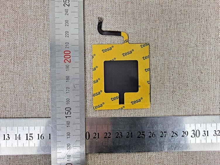
PFRFXRD2530FAW
Jul 27, 2021X-ray Detector
Equipment Class
DXX - Part 15 Low Power Communication Device Transmitter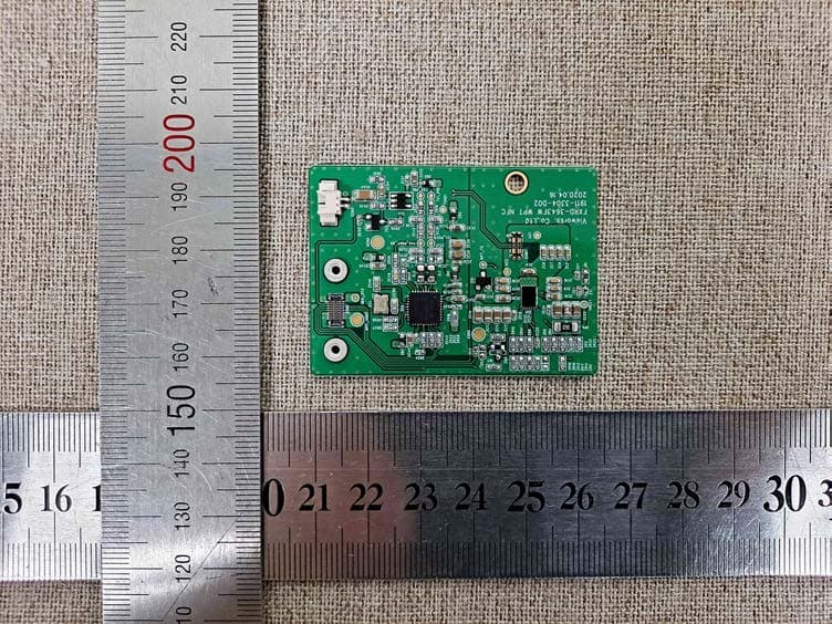
PFRFXRD4343FAW
Jul 27, 2021X-ray Detector
Equipment Class
DXX - Part 15 Low Power Communication Device Transmitter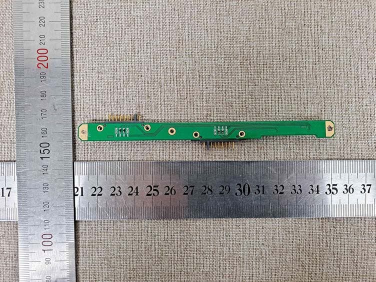
PFRFXRD3643FAW
Jul 27, 2021X-ray Detector
Equipment Class
DXX - Part 15 Low Power Communication Device Transmitter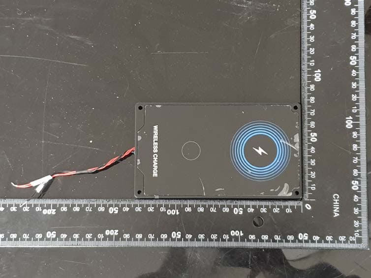
PFRFXRC05A
Jul 07, 2021Wireless Power Transmitter
Equipment Class
DCD - Part 15 Low Power Transmitter Below 1705 kHz