PG5PS001BCI2001Universal Remote Control
Brilliant Concepts International Limited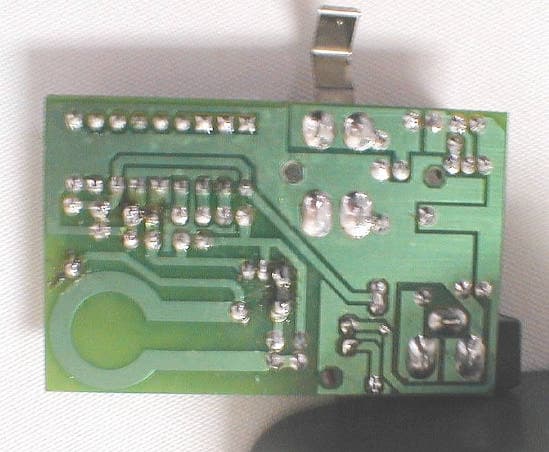
Click to zoom
Application Details
- Equipment Class
- DSC - Part 15 Security/Remote Control Transmitter
- Date of Grant
- Mar 29, 2001
- Application Purpose
- Original Equipment
- Date of Application
- Mar 29, 2001
- Equipment Note
- Universal Remote Control
- Frequency Range
- 311.00000000 - 311.00000000
- Country
- Hong Kong
Documents & Files
Document Text
Text extracted from the exhibit documents filed with the FCC. Open a document above to read the original.
Block Diagram
Brilliant Concepts PS-001-TX FCC ID: PG5PS001BC1200I Block Diagram DC Power In DC Charging Circuit (TQ2) Cradle for Remote CALL Switch (Momentary) HT12E Encoder Oscillator Circuit (TQ1) PCB Antenna Pulse Train
ID Label/Location Info
FCC Label Label Location (Bottom of Base Unit)
Internal Photos
EUT Cover Removed PCB Top PCB Bottom
Operational Description
Brilliant Concepts PS-001-TX FCC ID: PG5PS001BC1200I Theory of Operation: The PS-001-TX is used with a TV/Video remote control (the PS-001-RX). The function of the product is to provide a radio frequency signal from the base unit (PS-001-TX) and the remote control (PS-001-RX) to help users locate the remote control. The PS-001-TX is a radio frequency transmitter operating at 311.96 MHz. The frequency of operation is determined by the tank circuit composed of TL1, TC3 and TC1 and the printed circuit board antenna. Upon application of power to the oscillator circuit (around TQ1), the transistor circuit begins to oscillate. The HT12E encoding chip provides base drived to TQ1, turning the transistor ON and OFF in a pulse-modulated mode. The encoding of the HT12E is set to produce a pulse train that is recognized by the receiver embedded in the TV remote control. The unit transmits only when the momentary CALL button is pressed. The PS-001-TX also provides a base for charging of the remote control. This is supplied by TQ2, configured as a linear voltage regulator which drops the 12V input voltage to 3.6VDC to charge the remote control.
Test Report
FCC CERTIFICATION TEST REPORT for Brilliant Concepts International, Ltd. 2303-2308, Metropole Square 2 On Yiu Street, Shatin, N.T. Hong Kong FCC ID: PG5PS001BCI2001 February 23, 2001 WLL PROJECT #: 6345X This report may not be reproduced, except in full, without the prior written consent of Washington Laboratories, Ltd. Brilliant Concepts International, Ltd. FCC ID: PG5 PS001BCI2001 WLL Project #:6345X i TABLE OF CONTENTS Statement of Qualifications 1.0 INTRODUCTION...........................................................................................................................................................1 1.1 SUMMARY......................................................................................................................................................................1 2.0 DESCRIPTION OF EQUIPMENT UNDER TEST (EUT).................................................................1 3.0 TEST CONFIGURATION............................................................................................................................................2 3.1 TESTING ALGORITHM.................................................................................................................................................2 3.2 CONDUCTED EMISSIONS TESTING...........................................................................................................................2 3.3 RADIATED EMISSIONS TESTING...............................................................................................................................2 3.3.1 Radiated Data Reduction and Reporting........................................................................................................3 Tables Table 1. Conducted Emissions Results Table 2. Radiated Emissions Results Table 3. System Under Test Table 4. Interface Cables Used Table 5. Measurement Equipment Used Exhibits Exhibit 1 Duty Cycle Calculations Exhibit 2 Carrier Bandwidth Data Appendices Appendix A. Statement of Measurement Uncertainty Appendix B. Modifications Brilliant Concepts International, Ltd. FCC ID: PG5 PS001BCI2001 WLL Project #:6345X ii STATEMENT OF QUALIFICATIONS for Chad M. Beattie Washington Laboratories, Ltd. I am a NARTE-Accredited EMC Test Laboratory Engineer, with an Associates in Electronic Systems Technology. I have ten years of electronics experience, the last six years being directly involved in EMI testing. I am qualified to perform EMC testing to the methods described in this test report. The measurements taken within this report are accurate within my ability to perform the tests and within the tolerance of the measuring instrumentation. By: ________________________ Chad M. Beattie Compliance Engineer Date: February 23, 2001 Brilliant Concepts International, Ltd. FCC ID: PG5 PS001BCI2001 WLL Project #:6345X 1 FCC CERTIFICATION TEST REPORT for FCC ID: PG5PS001BCI2001 1.0 Introduction This report has been prepared on behalf of Brilliant Concepts International, Ltd. to support the attached Application for Equipment Authorization. The test and application are submitted for a Periodic Intentional Radiator under Part 15.231 of the FCC Rules and Regulations. The Equipment Under Test was the PS-001 wireless remote control locator contained in the rechargeable base of a television remote control. All measurements herein were performed according to the 1992 version of ANSI C63.4. The measurement equipment conforms to ANSI C63.2 Specifications for Electromagnetic Noise and field Strength Instrumentation. Calibration checks are made periodically to verify proper performance of the measuring instrumentation. All measurements are performed at Washington Laboratories, Ltd. test center in Gaithersburg, MD. Site description and site attenuation data have been placed on file with the FCC's Sampling and Measurements Branch at the FCC laboratory in Columbia, MD. Washington Laboratories, Ltd. has been accepted by the FCC and approved by NIST NVLAP (NVLAP Lab Code: 200066-0) as an independent FCC test laboratory. All results reported herein relate only to the equipment tested. The measurement uncertainty of the data contained herein is ±2.3 dB. Refer to Appendix A for Statement of Measurement Uncertainty. This report shall not be used to claim product endorsement by NVLAP or any agency of the US Government. 1.1 Summary The Brilliant Concepts International, Ltd. PS-001 complies with the limits for a Periodic Intentional Radiator under Part 15.231 of the FCC Rules and Regulations. 2.0 Description of Equipment Under Test (EUT) The Brilliant Concepts International, Ltd. PS-001 (EUT) is a 311 MHz transmitter used for the purpose of locating a television remote control. The transmitter is located in an AC powered base that is also used as a cradle for the remote control for charging. Power is provided by 3 “AAA” rechargeable batteries that are replenished from a 120VAC wall adapter. When the “call” button on the base is pressed, the RF signal will be transmitted to the receiver (FCC DoC approval) located in the remote control. The remote control will then emit an audible signal for aid in locating the unit. Brilliant Concepts International, Ltd. FCC ID: PG5 PS001BCI2001 WLL Project #:6345X 2 3.0 Test Configuration To complete the FCC testing, the base unit was connected to the AC power and was configured to continuously transmit the call signal. All testing was performed at 120VAC. 3.1 Testing Algorithm The transmitter was turned on and constantly transmitting. The unit was tested in one orthogonal plane as it is designed to sit on top of a table. Worst case emissions are recorded in the data tables. 3.2 Conducted Emissions Testing The EUT was placed on an 80 cm high 1 x 1.5 m non-conductive table above a ground plane. Power to the CPU was provided through a Solar Corporation 50 Ω/50 μH Line Impedance Stabilization Network bonded to a 3 x 2 meter ground plane. The LISN has its AC input supplied from a filtered AC power source. Power and d…
Text truncated - open the document above for the full version.
Test Setup Photos
Conducted Emissions Radiated Emissions
Contact Information
Applicant
Chun Hing Pony CHAN(Director)
Technical Contact
Washington Laboratories, Ltd.Gregory M Snyder
[email protected]301 417 0220
7560 Lindbergh Dr. · Gaithersburg, Maryland · United States
Test Firm
Washington Laboratories, Ltd.Michael Violette
Technical Specifications
| # | Rule Parts | Frequency Range | Power Output |
|---|---|---|---|
| 1 | 15.231 | 311 MHz - 311 MHz | - |