PGPOIS-W-WR300303RF-Identification System
Baumer Electric AG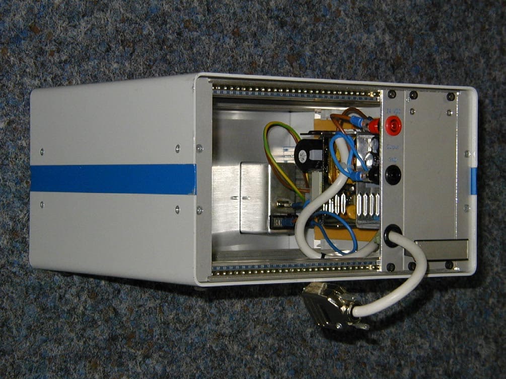
Click to zoom
Application Details
- Equipment Class
- DSR - Part 15 Remote Control/Security Device Transceiver
- Date of Grant
- Apr 22, 2001
- Application Purpose
- Original Equipment
- Date of Application
- Jan 30, 2001
- Equipment Note
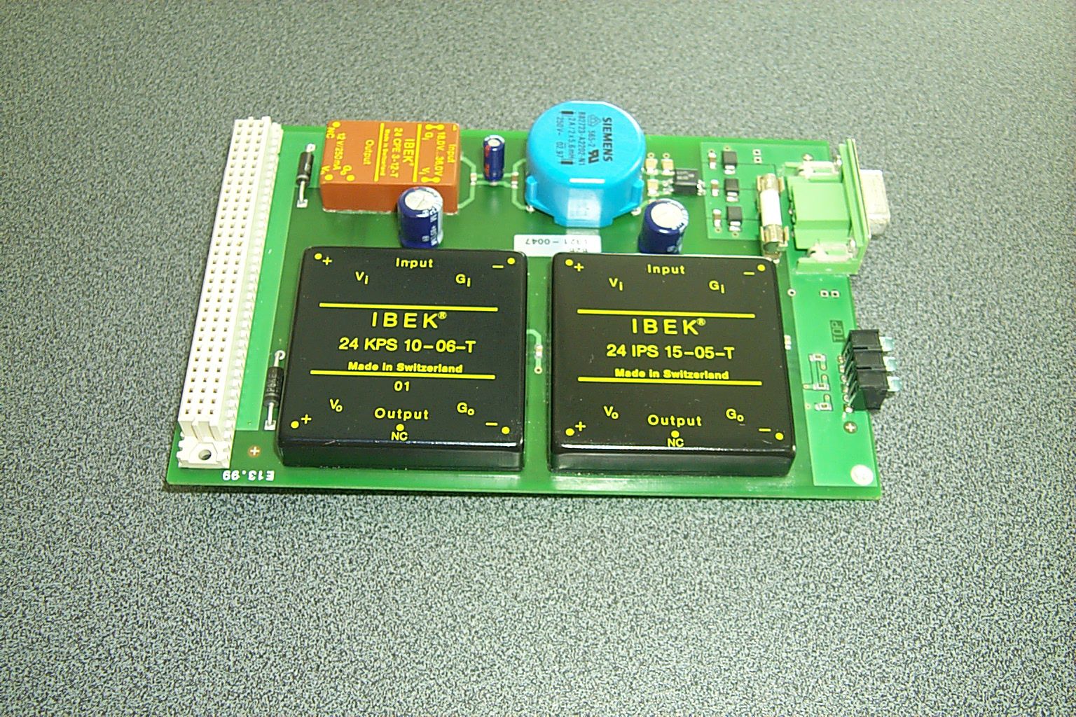
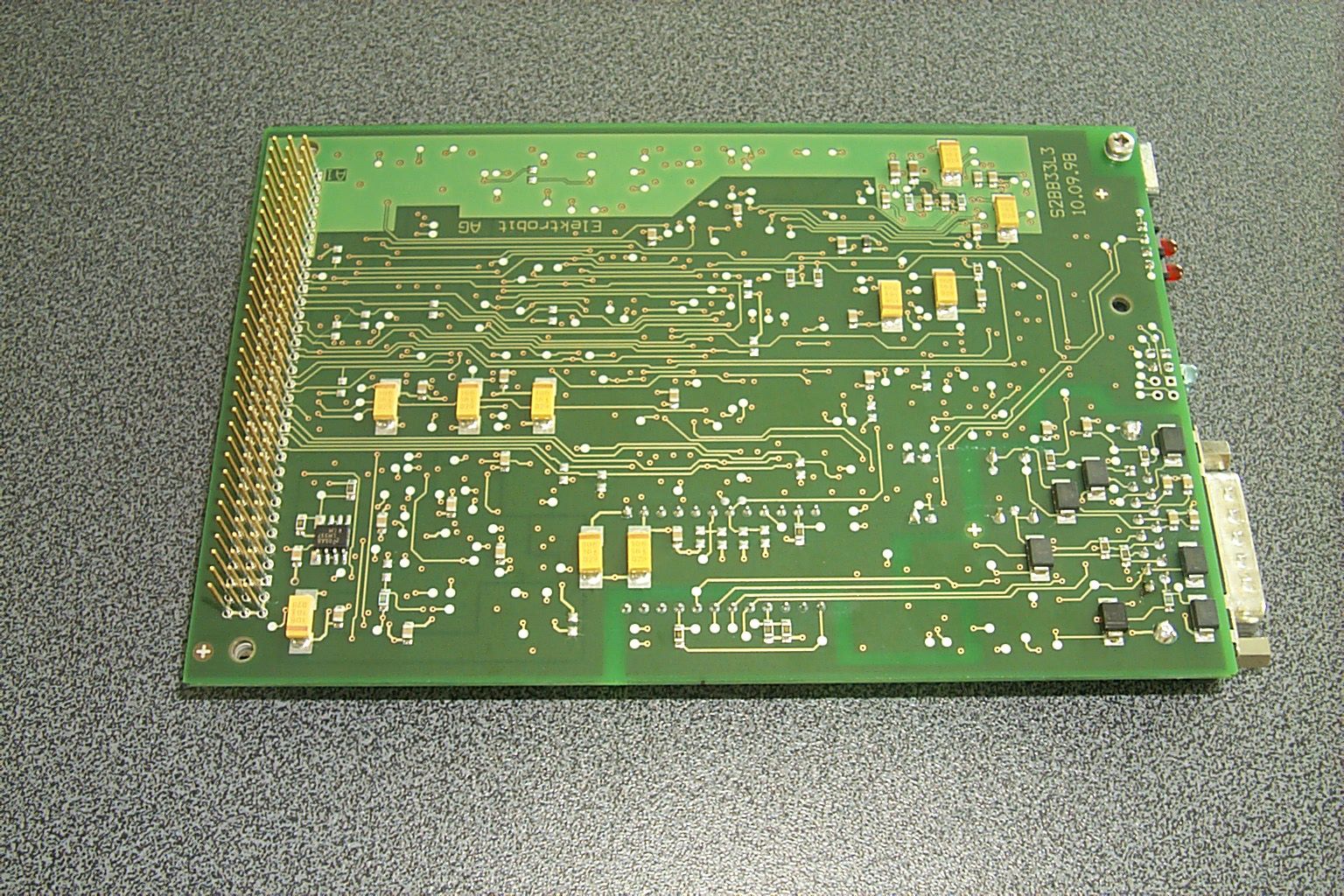
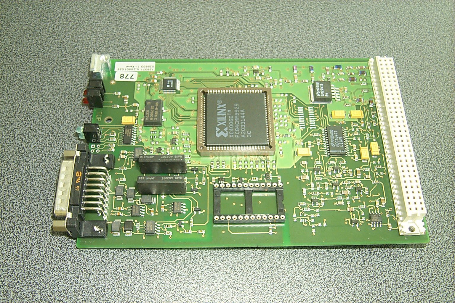
- RF-Identification System
- Frequency Range
- 2400.00000000 - 2445.00000000
- Company
- Baumer Electric AG
- Country
- Switzerland
Documents & Files
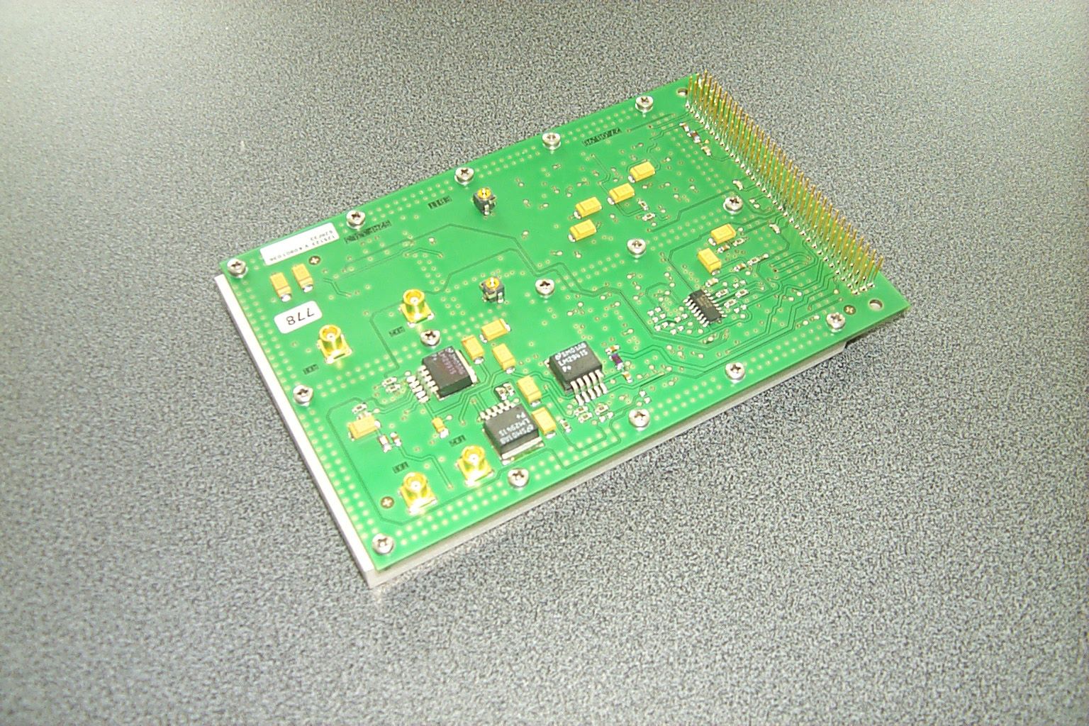
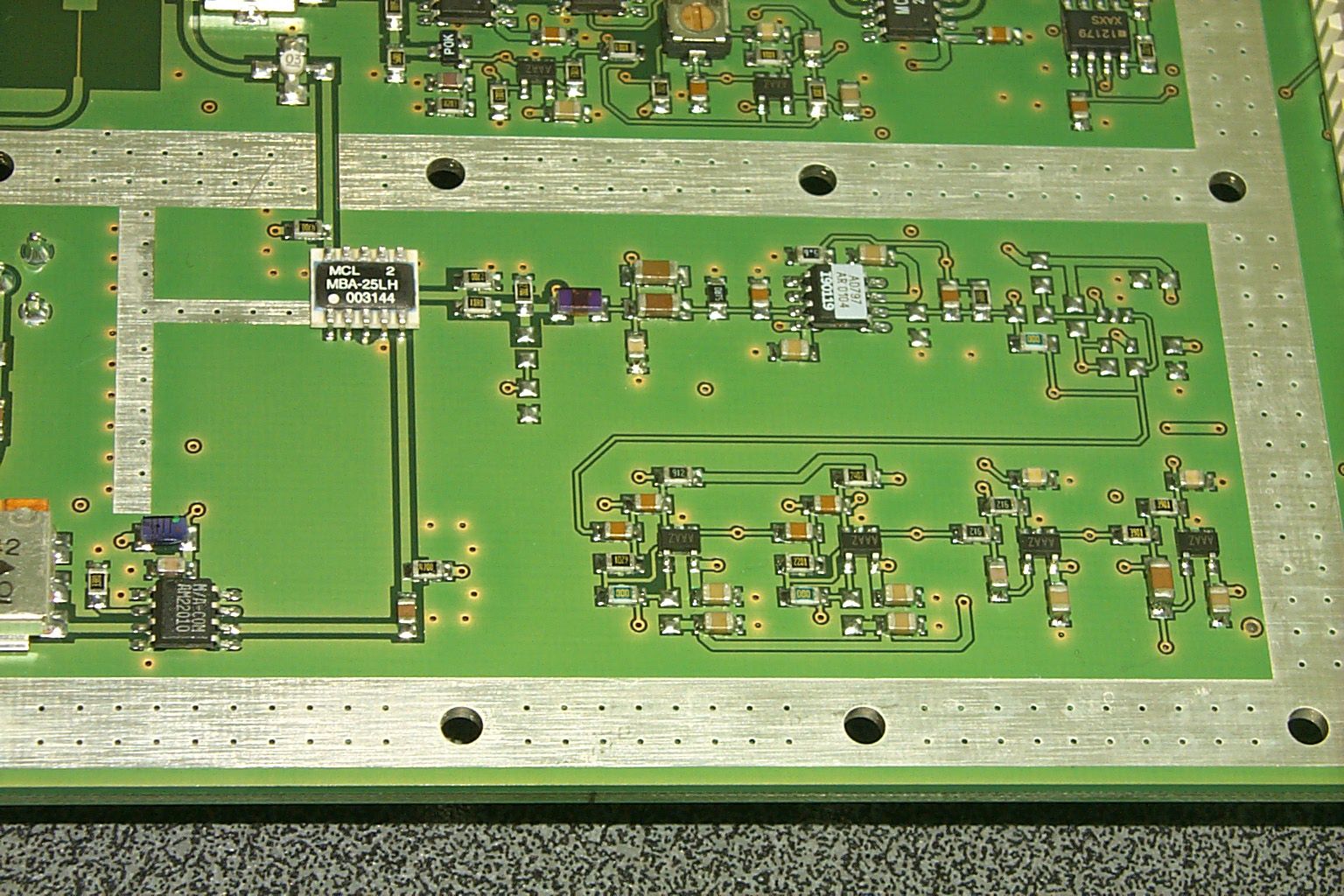
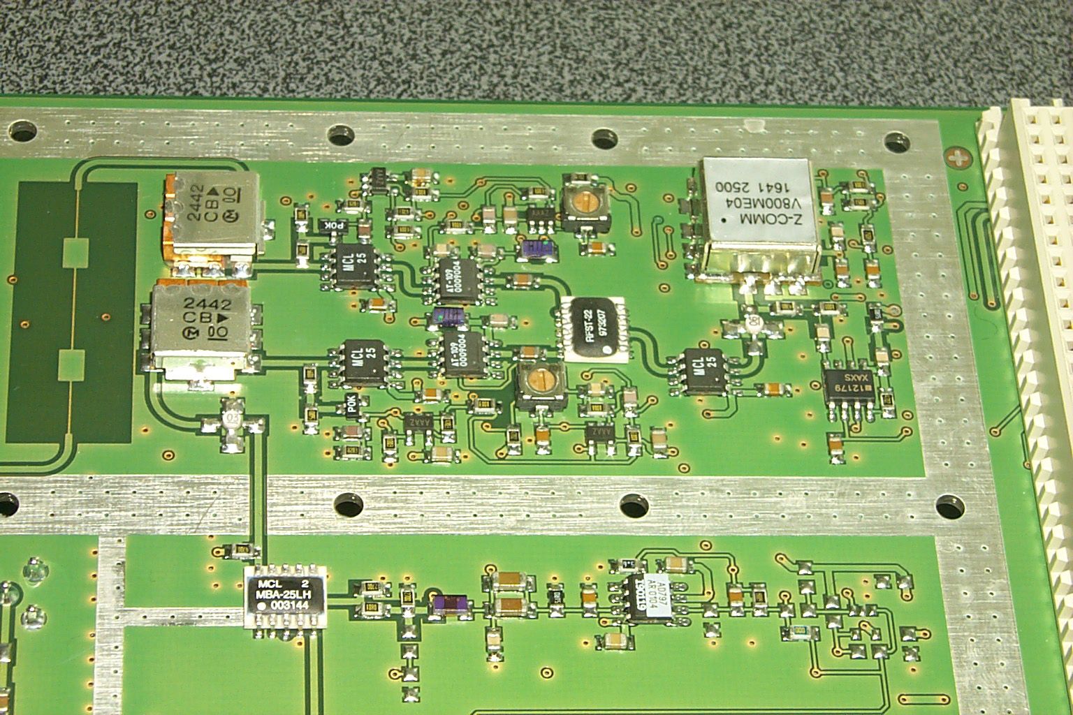
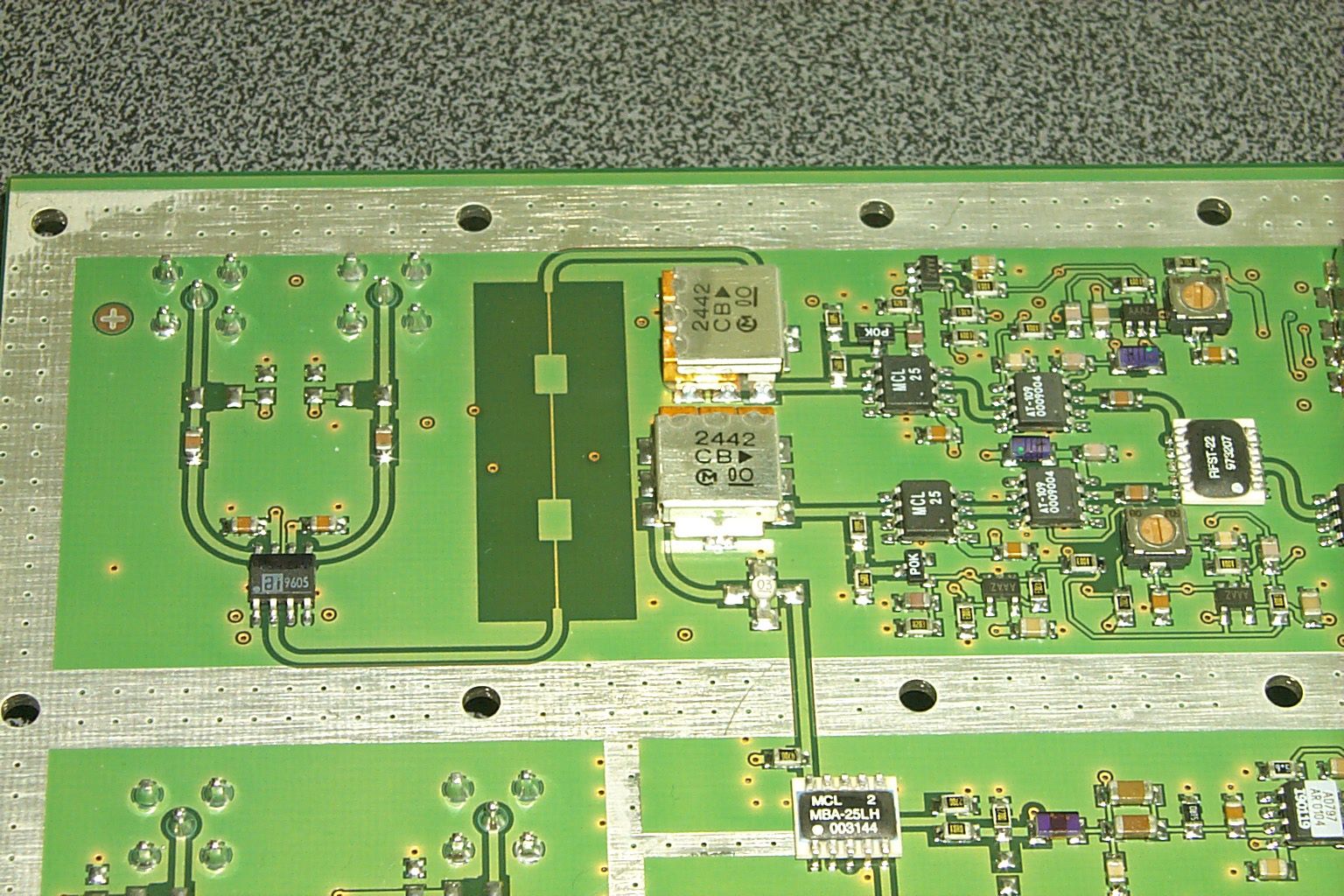
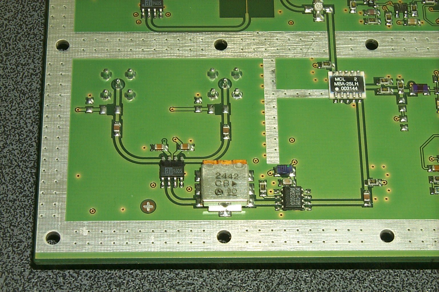
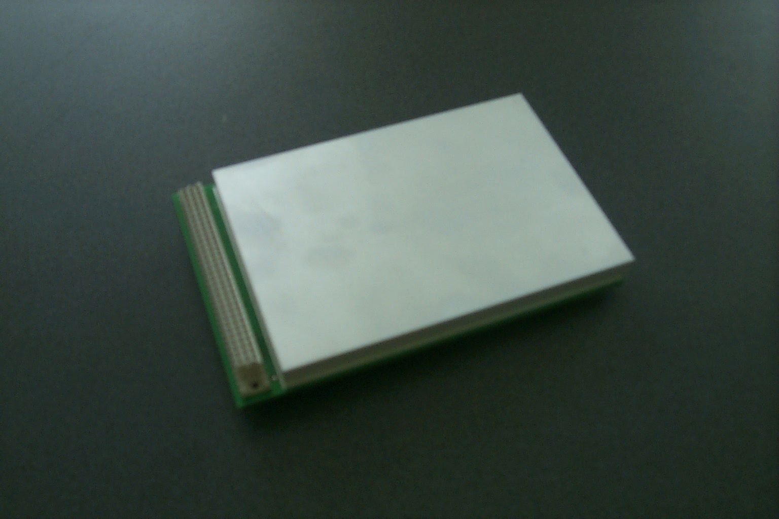
Document Text
Text extracted from the exhibit documents filed with the FCC. Open a document above to read the original.
Users Manual
Technical Documentation User’s Manual 2000 Baumer Ident AG Schweiz OIS-W: User's Manual Hardware P ROJECT P ROJECT : U SER ' S M ANUAL P ROJECT L EADER : C LEMENS Z EHNDER CC: - S UPPLIER : - D OCUMENT I NITIAL D ATE : 22. F EBRUARY 2000 L AST C HANGE : 10. O CTOBER 2000 V ERSION : 3.1 E F ILE : MGSY-2001-0302. DOC Baumer Ident AG File: Installation.doc Author: Clemens Zehnder Contents The Aim of the Document 1 User’s Instructions ............................................................................................................................1 1.1 Technical hot line ......................................................................................................................1 1.2 Certification ...............................................................................................................................1 1.3 Warranty....................................................................................................................................1 2 Safety Instructions ............................................................................................................................2 2.1 General Instructions ..................................................................................................................2 2.2 General Graphic Instruction ......................................................................................................3 3 Description of the Hardware Components .....................................................................................4 3.1 System ......................................................................................................................................4 3.2 Reader.......................................................................................................................................5 3.3 Tag ..........................................................................................................................................17 3.4 Antenna ...................................................................................................................................20 3.5 Cable .......................................................................................................................................24 3.6 Mounting Aids..........................................................................................................................27 4 How to connect the Hardware Components and switch on the Reader ....................................28 5 Personal Notices .............................................................................................................................31 Baumer Ident AG Author: Clemens Zehnder File: Installation.doc Contents of the pictures Picture 2-1: general graphic instructions ............................................................................................................................................3 Picture 3-1: system; general view.......................................................................................................................................................4 Picture 3-2: reader (R)........................................................................................................................................................................6 Picture 3-3: mechanical dimensions of the reader (R), without case .................................................................................................9 Picture 3-4: tag (T) ...........................................................................................................................................................................17 Picture 3-5: mechanical dimensions of the tags (T)..........................................................................................................................19 Picture 3-6: antenna (A); on the left with and on the right without circulator .....................................................................................20 Picture 3-7: antenna diagram WA-x1xx ............................................................................................................................................21 Picture 3-8: antenna diagram WA-x3xx ............................................................................................................................................22 Picture 3-9: antenna diagram WA-x4xx ............................................................................................................................................22 Picture 3-10: mechanical dimensions of the antennas (A)................................................................................................................23 Picture 3-11: rf cable (C) ..................................................................................................................................................................24 Picture 3-12: mechanical dimensions of the rf cables (C).................................................................................................................26 Picture 4-1: hardware connections ...................................................................................................................................................28 Contents of the tables Table 1-1: area of validity ...................................................................................................................................................................2 Table 3-1: terms of the system...........................................................................................................................................................4 Table 3-2: terms of the reader (R) ......................................................................................................................................................7 Table 3-3: overview of the readers (R) ............................................................................…
Text truncated - open the document above for the full version.
Users Manual
Application Note OIS-W Interface Specification 2000 Baumer Ident AG Switzerland OIS-W Reader Communication Interface P ROJECT P ROJECT : C OMMUNICATION I NTERFACE A UTHOR : W. S TEHLING A TTN : S YSTEM INTEGRATORS CC: D OCUMENT C REATED : 08. D ECEMBER 1999 L AST C HANGE : 27. S EPTEMBER 2000 V ERSION : VERSION 1.1 F ILE : SPWR-2101-0001. DOC Baumer Ident AG OIS-W Interface Specificatio n date: 20.02.2001 author: wst file: Interface.doc version 1.0 page: 2 / 2 Content History Related documents About the document Disclaimer 1 Introduction 4 2 Hardware requirements 4 3 Reader operating modes 5 3.1 Automatic Data Transmission 5 3.2 Communication upon request 6 3.3 Code lookup table 7 4 rotocol overview 8 4.1 General message structure 8 4.2 Data coding and byte order 9 5 Communication messages 10 5.1 Automatically transmitted messages 10 5.1.1 TAG_ID_IND: Send code information 10 5.1.2 PARAM_DATA_REP: Send extended code information 11 5.1.3 RESET_IND: Reset indication of reader 12 5.2 Request Information from reader 12 5.2.1 VERSION_REQ: Get software version information from reader 12 5.3 Information transmitted to the reader 13 5.3.1 DOWNLOAD_REQ: Download lookup table to reader 13 5.4 Auxiliary Port Information and Settings 15 Appendix A: CRC calculation 16 Appendix B: OIS-W messages 17 1 Automatically transmitted messages ......................................................................................17 2 Request information from the reader ......................................................................................17 3 Information transmitted to the reader ......................................................................................19 Appendix C: C/C++ header definitions 20 1 Global Definitions ....................................................................................................................20 2 Size definition of variables.......................................................................................................21 3 Structure definitions ................................................................................................................21 4 Definition of message numbers ..............................................................................................23 5 Error numbers .........................................................................................................................24 Baumer Ident AG OIS-W Interface Specificatio n date: 20.02.2001 author: wst file: Interface.doc version 1.0 page: 3 / 3 History 9HUVLRQ'DWH&KDQJH$XWKRU 1.0 99/12/08 first draft wst 1.1 00/09/27 modification on AUX_REP message and auxiliary heg Related documents [1]: Kühn, I., STAR2 SW Interface Specification, V 1.05 (1999/11/03), Elektrobit AG [2]: Zehnder, C., OIS-W User's Manual , V 3.0E (1999/09/28), Baumer Ident AG, MSGY-2001-305 About the document This application note describes the communication protocol of the OIS-W reader unit. It is intended for system integrators who need to set up the host's part of the communication. The protocol used with the serial interfaces will be explained in detail. Disclaimer The information contained in this document is believed to be accurate and reliable. It is based on the pro- tocol stack version 2.28. However, no responsibility is assumed by Baumer Ident for its use, nor for any infringements of patents or other rights of third parties which may result from its use. No license is granted by implication or otherwise under any patent or patent rights of Baumer Ident. © Baumer Ident AG, 2000 Baumer Ident AG OIS-W Interface Specificatio n date: 20.02.2001 author: wst file: Interface.doc version 1.0 page: 4 / 4 1 Introduction The OIS-W reader is fully programmable, i.e. there are no switches or jumpers to set, everything can be configured by software. Configuration parameters as well as the operating system itself may be downloaded in the field. A host computer may be connected to each of the two serial interfaces of the ba- sic reader unit. The main application of the serial interfaces is to transmit status information to a host computer. If the reader detects a valid code ID the information may be sent automatically or on request. The reader can be configured to run continuously or to start a measurement triggered by a switch or by computer. The protocol used to communicate with the reader is similar to the popular Siemens 3964R protocol. It will be described in subsequent chapters. 2 Hardware requirements The two serial interfaces of the reader are functional identical. Each may be used to connect to a host. They differ in the physical signal levels only: the upper one corresponds electrically to RS 232, the lower one to RS 422 levels (Table 2-1 and Table 2-2, respectively). 1 Only RxD and TxD are currently supported. 2 Internally connected to GND via 195 Ω. Signal Level RS232 Baud rates default 9600 baud optional 115'200 baud Parameter 8 bit, 1stop bit, no parity Connector 9-Pin D-Sub, male (DTE) Pin Assignment 1 DCD DSR 6 2 RxD RTS 7 3 TxD CTS 8 4 DTR RI 9 5 GND Table 2-1: RS 232 serial interface of the basic OIS-W reader unit 1 Signal level: RS422 Baud rates: default 9600 baud optional 115'200 baud Parameter 8 bit, 1stop bit, no parity Plug 9-Pin D-Sub, female (DTE) Pin assignment 5 GND 2 RxD- 9 4 RxD+ 8 3 TxD+ 7 2 TxD- 6 1 GND 2 Table 2-2: RS 422 serial interface of the basic OIS-W reader unit Baumer Ident AG OIS-W Interface Specificatio n date: 20.02.2001 author: wst file: Interface.doc version 1.0 page: 5 / 5 3 Reader operating modes Basically, the reader may operate in one of two main modes: triggered or free running. In triggered mode a new measurement starts as soon as an external signal is supplied or a trigger message from the host is received. In free running mode the reader is looking continuously for a valid identification. An identification message (or an appropriate error message in triggered mode) can be sent to a host in two ways: automatically or on request by t…
Text truncated - open the document above for the full version.
Users Manual
Technical Documentation User’s Manual 2000 Baumer Ident AG Switzerland OIS-W: User's Manual Service Software Development P ROJECT P ROJECT : U SER ' S M ANUAL P ROJECT L EADER : C LEMENS Z EHNDER CC: - S UPPLIER : - D OCUMENT I NITIAL D ATE : 12. A UGUST 1999 L AST C HANGE : 10. O CTOBER 2000 V ERSION : 3.1 E F ILE : MSGY-2001-0305 A . DOC Baumer Ident AG Author: Clemens Zehnder File: Maintenance-SW.doc Contents The Aim of the Document 1 User’s Instructions ............................................................................................................................1 1.1 Technical hot line ......................................................................................................................1 1.2 Certification ...............................................................................................................................1 1.3 Warranty....................................................................................................................................1 2 How to install the Service Software based on a PC.......................................................................2 2.1 System Requirements ...............................................................................................................2 2.2 How to copy the enclosed Files into the Working Directory ......................................................2 2.3 How to install and start-up the Application „DEVELOP.EXE“ with MS-DOS.............................2 2.4 How to install and start-up the Application „Develop.exe“ with Windows 95.............................3 2.5 Starter Picture of the Application „Develop.exe“ .......................................................................4 3 How to operate the Service Software based on a PC ....................................................................5 3.1 Introduction................................................................................................................................5 3.2 Keys and Combinations of Keys of the Man Machine Interface................................................8 4 Description of the Man Machine Interface ......................................................................................9 4.1 Window 1 ..................................................................................................................................9 4.2 Window 2 ................................................................................................................................30 4.3 Window 3 ................................................................................................................................48 5 How to put into Practice .................................................................................................................54 5.1 Logistics ..................................................................................................................................54 5.2 Access Control ........................................................................................................................62 6 If you have a Problem .....................................................................................................................63 7 Remote Diagnostics ........................................................................................................................64 8 Glossary ...........................................................................................................................................68 9 Notice................................................................................................................................................69 Baumer Ident AG Author: Clemens Zehnder File: Maintenance-SW.doc Contents of the Pictures Picture 2-1: start up with windows 95 .................................................................................................................................................3 Picture 2-2: Develop.exe start picture.................................................................................................................................................4 Picture 3-1: man machine interface (W) .............................................................................................................................................5 Picture 4-1: OIS-W service software development (S01)....................................................................................................................9 Picture 4-2: system information........................................................................................................................................................10 Picture 4-3: operation mode settings................................................................................................................................................12 Picture 4-4: tag structure settings.....................................................................................................................................................16 Picture 4-5: reader settings ..............................................................................................................................................................19 Picture 4-6: look up table .................................................................................................................................................................22 Picture 4-7: interface settings...........................................................................................................................................................24 Picture 4-8: monitor settings ............................................................................................................................................................26 Picture 4-9: aux ports settings .............................................................................................................................…
Text truncated - open the document above for the full version.
Cover Letter(s)
confidential.doc1/104.04.01/per Federal Communications Commission Equipment Authorization 7435 Oakland Mills Road Columbia, MD 21046 April 3rd 2001 Re : Request confidential Treatment, FCC ID PGPOIS-W-WR300303 Dear Sirs Baumer Electric requests that the material in the schematics and Operational description by the application of PGPOISW-WR300-303 should be withheld from public disclosure in accordance with section 0.459 of the commissions Rules, 47 C.F.R. 0.459. 1) The following material should be treated confidentially : schematics, internal photos and block diagrams. 2) The proceeding is that involving the application for equipment authorization (certification) under FCC ID No PGPOIS-W-WR300303. Note that a second application under FCC ID No PGPOIS-W-W300303 has been submitted due to a request of the FCC but has not been pursued and therefore will be dismissed (see also other cover letter). 3) The submitted material contains a detailed theory of operation and coding principle of the transponder IC. It contains patented firmware information and is therefore confidential business information. 4) This identification system is an innovative approach using a new technology based on surface acoustic waves and appropriate reader technology/signal processing. Identification for access, logistics and manufacturing control is a highly competitive area. Any technological information can lead to a substantial advantage over competitors. 5) Disclosure will give away several years of research and development efforts and will allow competitors unwarranted insight into the state of the product allowing them an advantage not available to Baumer. 6) The information for confidential treatment is sought is kept confidential by Baumer and not made available to third parties. 7) The only information which was available to the public was those described in the users manual, data sheets and brochures. 8) This material should not be disclosed for at least 10 years. While improvements in design are made relatively frequently design principles and manufacturing techniques will have a competitive value for years to come. Additionally this equipment will be used in access and security applications where information about data transmission and coding should not be made public to unauthorized persons. Kind regards Reto Peter Development Manager Identification systems Baumer Electric
External Photos
Label-position.doc1/427.02.01/per Label-position.doc2/427.02.01/per Label-position.doc3/427.02.01/per Label-position.doc4/427.02.01/per
ID Label/Location Info
1/1 montena emc sa CH-1728 Rossens – phone ++41 (0)26/411 93 33 – fax ++41(0)26/411 93 30 - http://www.montena.com MACHINERY - COMPONENTS – TECHNOLOGY Label Position of label montena emc sa Erich Staub
ID Label/Location Info
Label-position.doc1/227.02.01/per Label position WR0300 unit The label cannot be placed on the frontside due to components and screws on the frontside. The label will therefore be placed on the backside of the WR0300 Unit. Label position WR0303 unit The WR0303 consists of the WR0300 unit, a power supply and a common housing. Since the label of the WR0300 will be hidden an additional label is placed at the same position on the backside. The label cannot be placed on the frontside due to components and screws on the frontside. Label WR0300 Size 7cm x 3cm Label WR0303 Size 7cm x 3cm Backside Backside Label-position.doc2/227.02.01/per
ID Label/Location Info
compliance.doc 1/1 01.03.01/per Compliance declaration for the FCC Part15 Rules The following text will be inserted in the corresponding (certification) chapter of the users manual where the current European certification references are given : This device complies with Part 15 of the FCC Rules. Operation is subject to the following two conditions : (1) this device may not cause harmful interference, and (2) this device must accept any interference received, including interference that may cause undesired operation.
Test Report
montena emc sa CH-1728 Rossens - phone ++41 (0)26/411 93 33 - fax ++41 (0)26/411 93 30 - http://www.montena.com MACHINERY - COMPONENTS – TECHNOLOGY EMC Test laboratory accredited by the Swiss Federal Office of Metrology Laboratoire d'essai de CEM accrédité par l'Office Fédéral de Métrologie (Suisse) Durch das Eidgenössische Amt für Messwesen (Schweiz) akkreditiertes EMV-Prüflabor Registration number Numéro d'accréditation : Akkreditierungsnummer STS 024 Schweizerischer Prüfstellendienst Service suisse d'essai Servizio di prova in svizzera Swiss testing service Report no: Rapport no: 12'596 Bericht Nr: Title: Titre: Titel: Electromagnetic Compatibility Tests of the RF- Identification system OIS-W for determination of compliance with FCC part 15, subpart C Date of test: Date de l'essai: January 12 and 15, 2001 Prüfdatum: Customer: Client: Baumer Electric AG Kunde: Test place: Lieu de l'essai: Prüfort: montena emc sa CH-1728 Rossens Test performed by Essai effectué par : Prüfer Test report prepared by Rapport d’essai préparé par : Berichterstatter Test report controled and approved by Rapport d’essai contrôlé et approuvé par : Prüfbescheinigung Mr. Jacques DingMr. Jacques DingMr. Erich Staub Rossens, 2000-01-23(Issue Date / Date d'édition / Ausstelldatum) Main language / Langue principale / Hauptsprache: english / français / Deutsch This report may be reproduced in full, partial reproduction may be made only with the written consent of montena emc sa. The present document results from tests on a specimen and does not prejudge to the conformity of all the manufactured products. Ce rapport d’essai peut être reproduit en entier, une reproduction partielle ne peut être faite qu’avec l’autorisation écrite de montena emc sa. Le présent document résulte d'essais sur un spécimen. Il ne préjuge pas de la conformité de l'ensemble des produits fabriqués à l'objet essayé. Dieser Prüfbericht darf nur als Ganzes vervielfältigt werden. Auszüge dürfen nur mit schriftlicher Genehmigung von montena emc sa reproduziert werden. Dieser Bericht beinhaltet die Prüfergebnisse eines Mustergerätes. Es kann daraus nicht auf die Übereinstimmung der Seriegeräte mit dem Mustergerät geschlossen werden. No. / No. / Nr. :12'596 Date/Date/Datum :January 12 and 15, 2001 Title/Titre/Titel :Electromagnetic Compatibility Tests of the RF- Identification system OIS-W for determination of compliance with FCC part 15, subpart C montena Page/Page/Seite 2 / 37 montena emc sa CH-1728 Rossens - phone ++41 (0)26/411 93 33 - fax ++41 (0)26/411 93 30 - http://www.montena.com Contents / Table des matières / Inhaltsverzeichnis Page/Page/Seite 1. Summary of test results / Résumé des résultats d'essais / Zusammenfassung der Prüfergebnisse .................................................................................................................... 3 2. Client / Client / Kunde.......................................................................................................... 4 3. Equipment under test / Equipement à l'essai / Prüfling....................................................... 4 4. Test conditions / Conditions d'essai / Testbedingungen ..................................................... 5 5. Persons present / Personnes présentes / Anwesende Personen ....................................... 5 Emission Tests / Essais d'émission / Störaussendungsmessungen -Mains terminal interference voltage / Tension perturbatrice aux bornes d'alimentation / Störspannung auf den Energieversorgungsleitungen ................................ 6.1 - 6.3 -Radiated electromagnetic field / Champ électromagnétique rayonné / Störfeldstärke ....... 7.1 - 7.17 Appendixes / Annexes / Anhänge -Photos of the test set-ups / Photos des montages d'essai / Fotos der Prüfaufbauten ....... 8.1 - 8.2 -Technical documentation / Documentation technique / Technische Dokumentation.......... 9.1 – 9.10 Total number of pages Nombre total de pages du rapport: Total Anzahl Seiten 37 No. / No. / Nr. :12'596 Date/Date/Datum :January 12 and 15, 2001 Title/Titre/Titel :Electromagnetic Compatibility Tests of the RF- Identification system OIS-W for determination of compliance with FCC part 15, subpart C montena Page/Page/Seite 3 / 37 montena emc sa CH-1728 Rossens - phone ++41 (0)26/411 93 33 - fax ++41 (0)26/411 93 30 - http://www.montena.com 1. Summary of test results / Résumé des résultats d'essais / Zusammenfassung der Prüfergebnisse üPass / Réussi / Bestanden ΧFail / Pas réussi / Nicht bestanden o oo oNot applicable to this type of product / pas applicable à ce type de produit / nicht anwendbar für diese Produkteart No test / Pas d'essai / Nicht geprüft Test Type / Type d’essai / Art der PrüfungResult / Résultat / Ergebnis Emission / Emission / StöraussendungFCC, part C Mains terminal interference voltage § 15.207 Tension perturbatrice aux bornes d'alimentation § 15.207 Störspannung auf den Energieversorgungsleitungen § 15.207 ü üü ü Radiated electromagnetic field § 15.209, 15.249 Champ perturbateur § 15.209, 15.249 Störfeldstärke § 15.209, 15.249 ü üü ü The equipment is conform to all requirements of the standards: L'appareil répond à toutes les exigences fixées dans les normes : Das Gerät entspricht sämtlichen Anforderungen der Normen : FCC part C: § 15.207, 15.209 and 15.249 No. / No. / Nr. :12'596 Date/Date/Datum :January 12 and 15, 2001 Title/Titre/Titel :Electromagnetic Compatibility Tests of the RF- Identification system OIS-W for determination of compliance with FCC part 15, subpart C montena Page/Page/Seite 4 / 37 montena emc sa CH-1728 Rossens - phone ++41 (0)26/411 93 33 - fax ++41 (0)26/411 93 30 - http://www.montena.com 2. Client / Client / Kunde Client name and address Nom et adresse du client Name und Adresse des Kunden Baumer Electric AG Hummelstrasse 17 CH-8500 Frauenfeld Contact Person / Responsable / KontaktpersonMr. Reto Peter Telephone / Téléphone / Telefon++41 52 728 15 87 Fax / Télécopieur / Telefax++41 52 728 11 44 Mandate no / Mandat no / Auft…
Text truncated - open the document above for the full version.
Test Report
montena EMC Test laboratory accredited by the Swiss Federal Office of Metrology Laboratoire d'essai de CEM accrédité par l'Office Fédéral de Métrologie (Suisse) Durch das Eidgenössische Amt für Messwesen (Schweiz) akkreditiertes EMV-Prüflabor Registration number Numéro d'accréditation : Akkreditierungsnummer STS 024 Schweizerischer Prüfstellendienst Service suisse d'essai Servizio di prova in svizzera Swiss testing service Report no: Rapport no: 12'596A Bericht Nr: Title: Titre: Titel: Amendment to Report 12'596 : Emission measurements from 1 to 25 GHz Date of test: Date de l'essai: April 2 nd , 2001 Prüfdatum: Customer: Client: Baumer Electric AG Kunde: Test place: Lieu de l'essai: Prüfort: montena emc sa CH-1728 Rossens Test performed by Essai effectué par : Prüfer Test report prepared by Rapport d’essai préparé par : Berichterstatter Test report controled and approved by Rapport d’essai contrôlé et approuvé par : Prüfbescheinigung Mr Manfred PortmannMr Erich StaubMr Erich Staub Rossens, 2001-04-2(Issue Date / Date d'édition / Ausstelldatum) Main language / Langue principale / Hauptsprache: english / français / Deutsch This report may be reproduced in full, partial reproduction may be made only with the written consent of montena emc sa. The present document results from tests on a specimen and does not prejudge to the conformity of all the manufactured products. Ce rapport d’essai peut être reproduit en entier, une reproduction partielle ne peut être faite qu’avec l’autorisation écrite de montena emc sa. Le présent document résulte d'essais sur un spécimen. Il ne préjuge pas de la conformité de l'ensemble des produits fabriqués à l'objet essayé. Dieser Prüfbericht darf nur als Ganzes vervielfältigt werden. Auszüge dürfen nur mit schriftlicher Genehmigung von montena emc sa reproduziert werden. Dieser Bericht beinhaltet die Prüfergebnisse eines Mustergerätes. Es kann daraus nicht auf die Übereinstimmung der Seriegeräte mit dem Mustergerät geschlossen werden. No. / No. / Nr. :12'596A Date/Date/Datum :April 2nd, 2001 Title/Titre/Titel :Amendment to Report 12'596 : Emission…
Text truncated - open the document above for the full version.
Contact Information
Applicant
Matthias Sutter(Mr.)
Technical Contact
Montena EMC SAErich Staub
[email protected]+41 26 411 9333
Rte de Montenaz 75 · CH - 1728 Rossens · Switzerland
Non-Technical Contact
Montena EMC SAErich Staub
[email protected]+41 26 411 9333
Test Firm
Electrosuisse Montena EMCChristophe Perrenoud
Technical Specifications
| # | Rule Parts | Frequency Range | Power Output |
|---|---|---|---|
| 1 | 15C | 2.40 GHz - 2.44 GHz | - |
Other Applications from Baumer Electric AG
PGP-R670V
Aug 18, 2026Radar Distance Measuring Sensor
Equipment Class
VRD - Part 95 Vehicular Radar Systems
PGP-R600V
Feb 10, 2021Radar Distance Measuring Sensor
Equipment Class
DXX - Part 15 Low Power Communication Device Transmitter