PGQ72FM-08T72MHz Transmitter
Toytronix LLC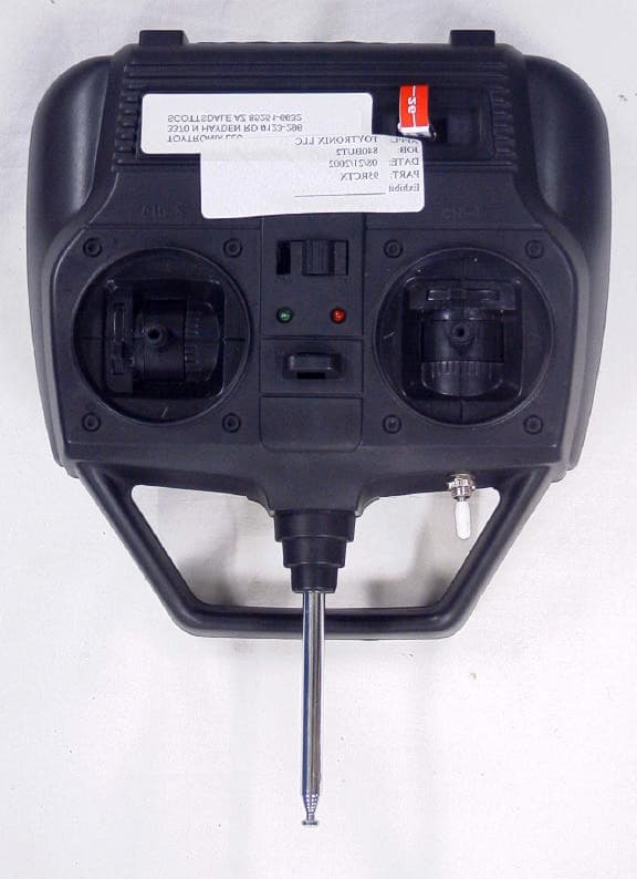
Click to zoom
Application Details
- Equipment Class
- TNB - Licensed Non-Broadcast Station Transmitter
- Date of Grant
- Jan 16, 2003
- Application Purpose
- Original Equipment
- Date of Application
- Jan 16, 2003
- Equipment Note
- 72MHz Transmitter
- Frequency Range
- 72.01000000 - 72.99000000
- Company
- Toytronix LLC
- Country
- United States
Documents & Files
Document Text
Text extracted from the exhibit documents filed with the FCC. Open a document above to read the original.
Users Manual
Introduction The 72FM-08T Dual Stick FM Radio is specifically made for simple 3 channel electric model airplanes. Transmitter Install 8 new AA Alkaline Batteries into the transmitter battery compartment. Do not use rechargeable batteries. Always be sure to insert the batteries in the proper polarity order. Switch the power on. A bright green and red light indicates good power. Replace the batteries when the green light gets dim compared to the red light. The crystals are not to be changed. Changing frequencies by the consumer will void the warranty and is a violation of FCC regulations. Always remember to never have the airplane “ON” without having the transmitter “ON”. The transmitter should always be turned “ON” first before supplying power to the airplane and turned “OFF’ last after removing power to the airplane. Hold the transmitter with two hands, gripping the sides in the palms of each hand. Do not touch the antenna while in use because it will affect the power output. Always make sure your antenna is attached and fully extended before use, otherwise your operating range will be greatly reduced and could result in damage to your transmitter, aircraft and/or injuries to yourself and others. Installation of the Receiver Check the polarity of all connections and ensure the connections are snug. WARNING: Do not trim the length of the receiver antenna wire. This will severly affect the operating range and could result in injury to yourself and others. Elevator and Rudder Servo Trim Settings Trim Setting before Flight The servo trim enables minor adjustment of the servo neutral position so that the plane will fly straight when the stick is in the center position. Before adjusting the servo trim, make sure that when both the stick and the servo trim is in the center position, (1) the servo arm is perpendicular to the push rods, and (2) the elevator and rudder of the plane is flush with the tail wing. Servo Reversing Switches The switches found in the battery compartment will reverse the servo direction. Range Testing With the plane resting on the ground and transmitter powered in hand with antenna fully extended, walk away about 100 pces while moving the control sticks back and forth. Listen carefully to make sure that the servo motor noise is heard only when you move the sticks. The control surfaces should operate smoothly with direct correspondence to your stick movements. Statement for U.S.A. This device complies with part 15 of the FCC rules. Operation is subject to the following two conditions: (1) this device may not cause harmful interference, and (2) this device must accept any interference that may cause indesired operation. Transmitter frequencies are not to be changed. Changing frequencies by the consumer will void the warranty and is a violation of FCC regulations.
Block Diagram
TRANSMITTER BLOCK DIAGRAM Oscillator and Mixer Q4 X-TAL 27MHz Band RF Driver Q2,3 RF OUT Q4 Fliter L3,L4 Moducator Q7,8 PULSE TRAIN ENCODER SWITCH, IC & VOLUME
Cover Letter(s)
Ref: FCC ID: PGQ72FM-08T Request for Confidentiality Dear Sirs: With regard to the referenced application, Toytronix LLC, is requesting confidentiality of certain sections of the accompanying documents. The documents for which Toytronix LLC is requesting confidentiality are: TX_Schematic.pdf (Transmitter Schematic 72FM-08T) This request is made under the provisions of Section 0.457(d) of the Commission’s Rules, and Section 552(b)(4) of the Freedom of Information Act. The material for which confidentiality is requested falls within the scope of Section 552(b)(4) as trade secrets and includes material covered by Section 0.459 of the Commission’s Rules. Sincerely, Rom Caroselli Toytronix LLC Equipment Authorization Division Office of Engineering and Technology Federal Communications Commission 7435 Oakland Mills Road Columbia, MD 21046 3370 N Hayden Rd. #123-296, Scottsdale, AZ 85251-6632 USA TEL: +1 (480) 947-5896 FAX: +1 (480) 994-4347 EMAIL: [email protected] October 15,2002
Operational Description
Circuit Description Transmitter 1.Oscillator & Mixer (Q1): A kind of radio frequency controlled Oscillator circuit via transmitting antenna is made of X-TAL, transistor (Q1, Q2, Q3, Q4), resistor, capacitor, coil (T1, T2). 2.Modulator (Q7, Q8): A circuit to shift pulse position to MIX occurred by IC1 and Q5, Q6 3.Pulse train encoder & switch (IC1, Q5, 6, 7, 8): A circuit to generate designated pulse to operate servosystem inside the moving vehicle. it is consists of IC (IC1), resistor, capacitor, transistor (Q5, 6, 7, 8), switch and volume. 4.Reverse switch (s2, 3, 4): A switch which can change moving vehicle's direction by servo's movement. 5. Volume(VR1,2): A circuit which can change the wide of pulse train. this is installed into transmitter's stick assembly and adjust moving direction of pulse to control servo's rotation direction or angles. 6.RF Driver Amp.(Q3): A circuit to amplify the mear frequency power mixed with pulse from generator to meet needed amplifying power increase. 7.RF Out(Q4): A circuit to amplify the radio frequency generated from RF Driver Amp. 8. Filter(T1,T2,L3,L4): A circuit to filtering unnecessary spurious frequency which is mixed with needed frequency from RF power amplifier.
Parts List/Tune Up Info
Alignment Procedure The item comes form the factory tuned. Only a qualified technician is allowed to tune this transmitter. Equipment needed: a service monitor that can measure field strength and frequency. Tuning tool. 1.Adjust the service monitor to the channel frequency. (72MHz) 2.Tune T1,T2 for maximum output.
Test Report
APPLICANT: TOYTRONIX LLC FCC ID: PGQ72FM-08T REPORT #: T:\T\Toytronix LLC\840ZUT2\840ZUT2TestReport.doc TABLE OF CONTENTS TABLE OF CONTENTS LIST APPLICANT: TOYTRONIX LLC FCC ID: PGQ72FM-08T TEST REPORT: PAGE 1......COVER SHEET - GENERAL INFORMATION & TECHNICAL DESCR. PAGE 2......TECHNICAL DESCRIP. CONTINUED. AND RF POWER OUTPUT PAGE 3......RF POWER OUTPUT, MODULATION CHAR., AND OCC. BANDWIDTH PAGE 4......OCCUPIED BANDWIDTH PLOT PAGE 5......FIELD STRENGTH OF SPURIOUS EMISSION PAGE 6......METHOD OF MEASURING RADIATED SPURIOUS EMISSIONS PAGE 7......FREQUENCY STABILITY PAGE 8-10...TEST EQUIPMENT LIST EXHIBIT CONTAINING: EXHIBIT 1..........FCC ID LABEL SAMPLE AND LOCATION EXHIBIT 2..........EXTERNAL PHOTOGRAPHS EXHIBIT 3..........INTERNAL PHOTOGRAPHS EXHIBIT 4..........BLOCK DIAGRAM EXHIBIT 5..........SCHEMATIC EXHIBIT 6..........USER'S MANUAL EXHIBIT 7..........CIRCUIT DESCRIPTION EXHIBIT 8..........ALIGNMENT PROCEDURE EXHIBIT 9..........TEST SET UP PHOTO EXHIBIT 10.........REQUEST FOR CONFIDENTIALITY LETTER APPLICANT: TOYTRONIX LLC FCC ID: PGQ72FM-08T REPORT #: T:\T\Toytronix LLC\840ZUT2\840ZUT2TestReport.doc Page 1 of 10 GENERAL INFORMATION 2.1033(c)(1)(2) TOYTRONIX LLC will sell the FCCID: PGQ72FM-08T Radio Control transmitter in quantity, for use under FCC RULES PART 95 SUBPART C. TOYTRONIX LLC 3370 N. HAYDEN ROAD # 123.296 SCOTTSDALE, AZ. 85251-6632 2.1033(c)(3) Instruction manual is included as exhibit #6. 2.1033 (4) Type of Emission: 6K4F1D 95.631(b)(1) Bn = 2M + 2DK M = 4,800 Bits per second D = 800 Hz (Peak Deviation) K = 1 Bn = 2(4800/2) + 2(800) = 4.8K + 1.6K = 6.4k ALLOWED AUTHORIZED BANDWIDTH = 8 kHz 95.633(b) Authorized Bandwidth 8KHz for RC Transmitter 2.1033(c)(5) Frequency Range: 72-73 MHz 95.623(a) 95.649 (6) Power Range and Controls: There are NO user Power controls. (6) Function of each electron tube or semiconductor device or other active circuit device: See Exhibit # 7. 95.639(b)(3) 7) Maximum Output Power: 32 milli Watts ERP. (8) DC Voltages and Current into Final Amplifier: FINAL AMPLIFIER ONLY Vce = 12.0 Volts DC Ice = 0.039A. Pin = 0.5 Watts 2.1033(c)(9) Tune-up procedure. The tune-up procedure is included as Exhibit # 8. APPLICANT: TOYTRONIX LLC FCC ID: PGQ72FM-08T REPORT #: T:\T\Toytronix LLC\840ZUT2\840ZUT2TestReport.doc Page 2 of 10 2.1033(c)(10) Complete Circuit Diagrams: The circuit diagram is included as part of Exhibit # 5. The block diagrams are included as Exhibit #4 of this report. (10) Description of all circuitry and devices provided for determining and stabilizing frequency is given in Exhibit 7 of this report. 2.1033(c)(11) The Equipment identification is shown as Exhibit # 1. 2.1033(c)(12) Photographs of the equipment are shown as Exhibits 2-3. 2.1033(c)(13) Equipment employing Digital modulation. N/A. 2.1033(c)(14) The data required by 2.1046-2.1057 follows; 2.1046 RF power is measured by the ERP SUBSTITUTION METHOD. There is no provisions to vary the power. With a nominal battery voltage of 12.0 VDC, and the transmitter properly adjusted the RF output measures: Po = 0.032 W 2.1046 RF power output. APPLICANT: TOYTRONIX LLC FCC ID: PGQ72FM-08T REPORT #: T:\T\Toytronix LLC\840ZUT2\840ZUT2TestReport.doc Page 3 of 10 2.1047 Modulation characteristics: AUDIO FREQUENCY RESPONSE The Voice is NOT allowed in this band. 2.1049 Occupied bandwidth: 95.635(b) (1) At least 25dB on any frequency removed from the center of the authorized bandwidth by more that 50% up to and including 100% of the authorized bandwidth. (10) At least 45dB on any frequency removed from the center of the authorized bandwidth by more that 100% up to and including 125% of the authorized bandwidth. (11) At least 55dB on any frequency removed from the center of the authori- zed bandwidth by more that 125% up to and including 250% of the authorized bandwidth. (12) At least 56+log10(T) on any frequency removed from the center of the authorized bandwidth by more that 250%. Test procedure diagram OCCUPIED BANDWIDTH MEASUREMENT Coupler Transmitter 50 ohm under test Resistive Wattmeter Spectrum Analyzer APPLICANT: TOYTRONIX LLC FCC ID: PGQ72FM-08T REPORT #: T:\T\Toytronix LLC\840ZUT2\840ZUT2TestReport.doc Page 4 of 10 OCCUPIED BANDWIDTH PLOT APPLICANT: TOYTRONIX LLC FCC ID: PGQ72FM-08T REPORT #: T:\T\Toytronix LLC\840ZUT2\840ZUT2TestReport.doc Page 5 of 10 2.1051 SPURIOUS EMISSIONS AT ANTENNA TERMINALS. NOT APPLICABLE, NO antenna port. This UUT has a permanently attached antenna. 2.1053 UNWANTED RADIATION: 95.635(1)(3)(7)(10)(11)(12) REQUIREMENTS: At least 56 + 10log(T) on any frequency removed from the center of the authorized bandwidth by more than 250%. 56 + 10log(0.032) = 41.05dB TEST DATA: Emission Frequency MHz ATTN dBc dBm Margin dB 72.34 0.0 15.1 0.00 144.68 62 -47 20.95 216.96 70 -55 28.95 289.36 62 -47 20.95 361.66 69 -54 27.95 433.96 65 -50 23.95 506.26 61 -46 19.95 578.58 64 -49 22.95 650.86 59 -44 17.95 723.20 65 -50 23.95 METHOD OF MEASUREMENT: The tabulated data shows the results of the radiated field strength emissions test. The spectrum was scanned from 30 MHz to at least the tenth harmonic of the fundamental. This test was conducted per TIA/EIA STANDARD 603 using the substitution method. Measurements were made at the open field test site of TIMCO ENGINEERING, INC. located at 849 NW State Road 45, Newberry, FL 32669 APPLICANT: TOYTRONIX LLC FCC ID: PGQ72FM-08T REPORT #: T:\T\Toytronix LLC\840ZUT2\840ZUT2TestReport.doc Page 6 of 10 Method of Measuring Radiated Spurious Emissions APPLICANT: TOYTRONIX LLC FCC ID: PGQ72FM-08T REPORT #: T:\T\Toytronix LLC\840ZUT2\840ZUT2TestReport.doc Page 7 of 10 2.1055(a)(1) Frequency stability: 95.623(b) Temperature and voltage tests were performed to verify that the frequency remains within the .002%, 20 ppm specification limit. The test was conducted as follows: The transmitter was placed in the temperature chamber at 25 degrees C and allowed to stabilize for one hour. The transmitter was keyed ON for one minute during which four frequency readin…
Text truncated - open the document above for the full version.
Contact Information
Applicant
Rom Caroselli(President)
Test Firm
Timco Engineering, Inc.S Sanders
Technical Specifications
| # | Rule Parts | Frequency Range | Power Output | Emission | Tolerance |
|---|---|---|---|---|---|
| 1 | 95C | 72.01 MHz - 72.99 MHz | 32.00 mW | 6K40F1D | 20.0000000000 ppm |