PGSEPIRBPRO-Find 406 EPIRB
PRO-Find Safety Incorporated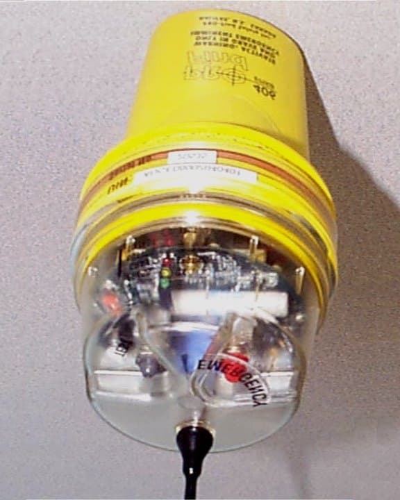
Click to zoom
Application Details
- Equipment Class
- GEP - 406 MHz EPIRB
- Date of Grant
- May 29, 2001
- Application Purpose
- Original Equipment
- Date of Application
- Jan 25, 2001
- Equipment Note
- PRO-Find 406 EPIRB
- Frequency Range
- 121.50000000 - 121.50000000
- Company
- PRO-Find Safety Incorporated
- Country
- Canada
Documents & Files
Document Text
Text extracted from the exhibit documents filed with the FCC. Open a document above to read the original.
Users Manual
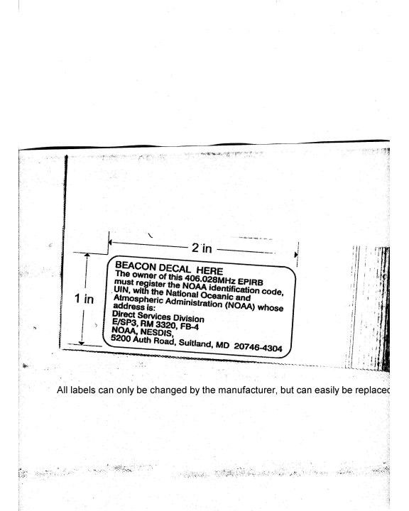
Mail or fax to: SARSAT Beacon Registration E/SP3, RM 3320, FB-4 NOAA 5200 Auth Road Suitland, MD 20746-4304 FAX: 301-568-8649 Check the appropriate box: Unique Identifier Number (15 Characters) EPIRB Category (check one) Owner Information Owners Name (Last, First Middle Initial): Mailing Address: Country: Telephone:Work: Vessel Data Type:Sail Power Color: Radio Equipment: Telephone NumbersINMARSAT:Cellular: Vessel Name:Call Sign: Documentation or Registration Number: Length Overall (ft):Capacity (crew & passengers): Homeport (Marina/Dock City/State) : Additional Information: Emergency Contacts Name of Primary 24-Hour Emergency Contact: Telphone: (Home) (Work) Alternate 24-Hour Emergency Contact: Telphone: (Home) (Work) Signature:Date: If you have any questions about this form or EPIRB registration in general please call ____________________ Manufacturer Model Number: WARNING - failure to register this EPIRB with NOAA before installation could result in a monetary forfeiture being issued to the owner. (47 CFR 80.1061 (E)) EPIRB Registration Form New EPIRB Registration Change of EPIRB Ownership Change of EPIRB Information Category I (automatic activation)Category II (manual activation only) Sloop Fishing Yawl Tug Schooner INMARSAT TankerCabin CruiserOther Other VHFHFMFOther Check here if this EPIRB is a replacement for a previously registered EPIRB Cargo
Users Manual
Owner’s Manual E mergency P osition I ndicating R adio B eacon PRO-Find 406 TM Emergency Position-Indicating Radio Beacon Owner’s Manual UM-419-99-019 Version 1.0, March 14, 2001 271 Brownlow Avenue Halifax, NS B3B 1W6 Canada Telephone: 1-877-7SAFETY (1-877-772-3389) Facsimile: 902-468-3009 PRO-Find 406 TM Emergency Position-Indicating Radio Beacon March 14, 2001 i Table of Contents Registration....................................................................................................1 PRO-Find 406TM EPIRB ........................................................................2 Category I PRO-Find 406TM – Automatic Release Bracket .........4 Installation ................................................................................................4 How to use in case of emergency ......................................................6 Hydrostatic Release Replacement ......................................................7 Category ll PRO-Find 406TM – Manual Release Bracket ........... 10 Installation ............................................................................................. 10 How to use in case of emergency ................................................... 11 False Distress Alerts & De-Alerting ................................................... 12 Self Test ....................................................................................................... 14 Battery Replacement ................................................................................ 15 Approvals .................................................................................................... 19 PRO-Find 406TM Warranty Limited ................................................. 20 Annex A Registration Form & Prepaid Envelope ........................ 22 PRO-Find 406 TM Emergency Position-Indicating Radio Beacon 1 IMPORTANT Registration The PRO-Find 406.028 MHz EPIRB (Emergency Position Indicating Radio Beacon), when activated, automatically advises Search And Rescue (SAR) authorities that you are in distress. After activation of your PRO-Find 406 TM , SAR can identify you and begin the search for your vessel. However this only works if you properly register your PRO-Find 406 TM EPIRB. You must include your Universal Identification Number (UIN), which is printed on the unit. If you are a resident of the United States: To ensure the Mission Control Center/SAR center has the information required in case of an emergency you MUST register your PRO-Find 406 TM EPIRB with the National Oceanic and Atmospheric Association (NOAA). (Registration form Annex A) You must fill it out and send it to: SARSAT E/SP3, RM3320, FB-4, NOAA 5200 Auth Road Suitland, MD 20746-4304 USA Tel: 1-888-212-SAVE (7283) Fax: 1-301-568-8649 If you are a resident of Canada: You must register your PRO-Find 406 TM EPIRB with the National Search and Rescue Secretariat (NSS) and send your registration form to: Canadian Beacon Registry c/o National Search & Rescue Secretariat 4 th Floor, 275 Slater Street Ottawa, ON K1A 0K2 Canada Tel: 1-800-727-9414 Fax: 1-613-996-3746 The only reason you will need to contact NOAA or NSS, after sending in your registration card is for the following reasons: • There is a change in ownership of your vessel • You purchase a different vessel • You change your mailing address or phone number PRO-Find 406 TM Emergency Position-Indicating Radio Beacon March 14, 2001 2 PRO-Find 406 TM EPIRB PRO-Find 406 TM is an Emergency Position Indicating Radio Beacon (EPIRB) that sends a distress signal via UHF radio transmission on the 406.028 MHz frequency via satellite to the COSPAS-SARSAT network. COSPAS-SARSAT System Overview COSPAS-SARSAT is an international system that uses low altitude, near- polar orbiting satellites and geostationary satellites that assist in detecting and locating activated satellite EPIRBs operating in the 406.0 to 406.1 MHz band. A 406 MHz satellite EPIRB designed and manufactured to the standards published by COSPAS-SARSAT constitutes the satellite EPIRB portion of the COSPAS-SARSAT System developed and implemented by the COSPAS-SARSAT Partners (Canada, France, the Russian Federation, and the United States). COSPAS-SARSAT satellite transponders receive distress alert signals from EPIRBs transmitting on the 406 MHz frequency band. The COSPAS-SARSAT 406 MHz satellite EPIRB signal consists of a digital message that provides identification data, nationality and type of user. The satellite system determines the EPIRB position using precision doppler techniques on the 406 MHz signal. The satellites store this information and forward it to a ground station. The distress position is relayed to a Mission Control Center (MCC) where the distress alert and location information is immediately forwarded to an appropriate Search and rescue Point Of Contact (SPOC). The SPOC dispatches Search And Rescue (SAR) forces and the survivors are brought to safety. The Search And Rescue Forces u se the EPIRBs 121.5 MHz signal to home in on the emergency once they get in the vicinity of the reported distress position. PRO-Find 406 TM Emergency Position-Indicating Radio Beacon March 14, 2001 3 Category I – Automatic Release Bracket Category II – Manual Release Bracket Note: The cat egory I and category II EPIRB is the same unit. (Figure 1) The difference between the two is the brackets in which they are stored. For automatic activation, throw the unit in the water and it will automatically activate once the immersion sensors come in contact with water. The PRO-Find 406 TM EPIRB has an operating life of 48 hours. Operating Temperature Range -40 ° C to +55 ° C -40F to +131F Storage Temperature Range -50 ° C to +70 ° C -58F to +158F Figure 1 – PRO-Find 406 TM EPIRB PRO-Find 406 TM Emergency Position-Indicating Radio Beacon March 14, 2001 4 Category I PRO-Find 406 TM – Automatic Release Bracket Installation The primary function of the Category I PRO-Find 406 TM automatic release bracket is to automaticall…
Text truncated - open the document above for the full version.
External Photos
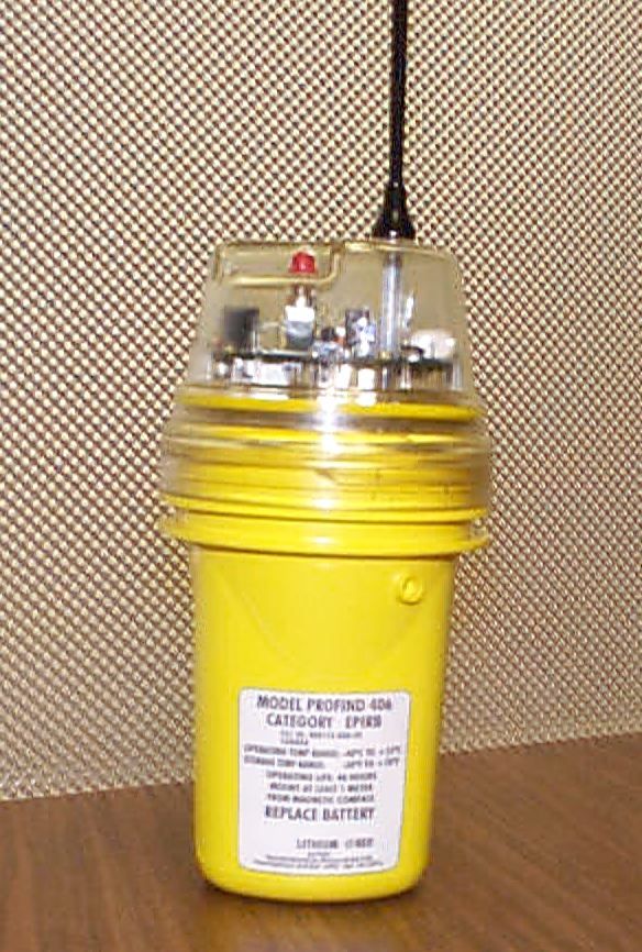
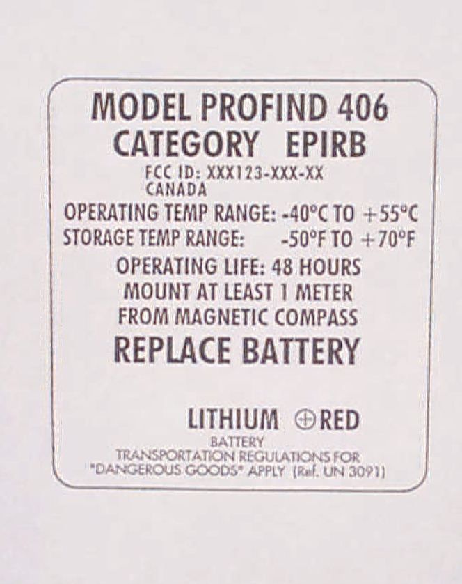
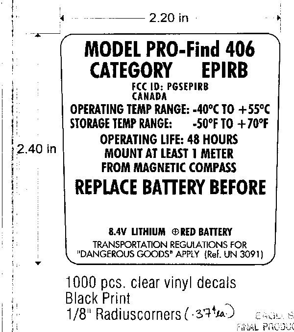
(12) Photographs of Equipment Photograph 1. Close up of EPIRB 2 Photograph 2. Full EPIRB 3 Photograph 3. Emergency and Test Buttons on EPIRB 4 Photograph 4. EPIRB and Battery
Internal Photos
(12) Photographs of Equipment Photograph 1. Top of Circuit Board 2 Photograph 2. Bottom of Circuit Board
Operational Description
FCC Technical report Technical Report – TR-419-15-006 V1.0 March 15, 2001 2 Table of Contents Executive Summary ............................................................................................................ 3 2.1033 .................................................................................................................................. 4 a)Application for Certification ................................................................................... 4 b)Application for Equipment Parts 11, 15, and 18 ..................................................... 4 c)Application for Equipment other than Parts 15 and Parts 18.................................. 4 (1) Name and Address of Manufacturer..................................................................... 4 (2) FCC Identifier ........................................................................................................ 4 (3) Installation Manual ................................................................................................ 4 (4) Types of Emission ................................................................................................. 4 (5) Frequency range .................................................................................................... 4 (6) Power Range.......................................................................................................... 5 (7) Maximum Power ................................................................................................... 5 (8) DC voltages and Currents...................................................................................... 5 (9) Tune up Procedure................................................................................................. 8 10) Schematics and descriptions ............................................................................... 10 (11) Photographs of Equipment Identification .......................................................... 14 (12) Photographs of Equipment ................................................................................ 17 (13) Digital Modulation............................................................................................. 23 (14) Data Required by 2.1046 through 2.1057.......................................................... 24 (15) Certification under Part 97 ................................................................................ 25 (16) Certification of AM broadcast ........................................................................... 25 (17) Application for Composite System.................................................................... 25 Annex A ............................................................................................................................ 26 Annex B............................................................................................................................. 31 Annex C............................................................................................................................. 33 3 Executive Summary This document contains all the information to comply with section 2.1033 “Application for Certification” of the FCC document. 4 2.1033 a) Application for Certification FCC form 731 was already filed. b) Application for Equipment Parts 11, 15, and 18 The Pro-Find 406 does not fall under parts 11, 15 or 18 so nothing is required here. c) Application for Equipment other than Parts 15 and Parts 18 (1) Name and Address of Manufacturer Se imac Limited 271 Brownlow Ave Dartmouth, Nova Scotia, Canada B3B 1W6 (2) FCC Identifier FCC ID: PGSEPIRB Applicant:PRO-Find Safety Incorporated Correspondence Reference Number:18401 731 Confirmation Number: EA99871 (3) Installation Manual The installation Manual is in Annex C (4) Types of Emission i)121.5 MHz -- 3K20A3N ii)406 MHz -- 16K0G1D (5) Frequency range 5 i) 406.028 MHz +/- .001 MHz ii) 121.5 MHz +/- .003 MHz (6) Power Range i)406.028 MHz5W +/- 2dB (3.15 W to 7.92 W) Power output has been designed for one power level of 5W. Some variation in the components will cause this power to vary but the power shall remain within the specification for this device. This is verified during testing. There are no means provided for power output level adjustment by the user. ii)121.5 MHz25 mW –0dB +6dB (25 mW to 100 mW) Power output has been designed for one power level of 50 mW. Some variation in the components will cause this power to vary but the power shall remain within the specification for this device. This is verified during testing. There are no means provided for power output level adjustment by the user. (7) Maximum Power i) 406.028 MHz7.92 W ii) 121.5 MHz100 mW (8) DC voltages and Currents Note all the currents given in this section are Continuous Wave currents and only represent the currents when the devices are ON. The EPRIB specification requires that the output be pulsed on and off so the average current is much less then the ON current. i) DC voltages and current into the Power Amplifier and Exciter for the 406.028 MHz transmitter are indicated in Figure 1 and Table 1. 6 PinDC VoltageCurrent Vd5 V1.8 A Vg2.6 V.3 nA Table 1. DC Voltage and Current of Final PA The dc voltages and current into the exciter for the Power Amplifier are as indicated in Table 2 and Figure 2. TX-ON2 C3 9 120 pF R5 6 18R R5 7 3.9 2K D S Q2 MR F15 172 1 3 C9 4 10n F C4 4 150 pF R5 5 1K L13 18. 5nH C3 5 150 pF L11 10 OHM BEA D HC B10- 100 1 2 C8 6 0.4 7uF L23 1.8 nH 5 V dc 5 V dc 2.6 V dc 3.3 V dc Figure 1. Schematic Showing DC Voltages into the Power Amplifier 7 PinDC VoltageCurrent Vcc15 V.03A Vcc25 V.26A PWRCNTL1.6 V.6 mA Table 2. DC Voltages and Current into the Exciter ii) DC voltages and currents into the 121.5 MHz Amplifier are indicated in Table 3 and Figure 3. 5VREG C25 150pF U2 RF 2104 1 2 3 4 5 6 7 8 16 15 14 13 12 11 10 9 VC C 1 GND1 GND2 VC C 2 RF IN GND3 GND4 PWR CN TL GND10 GND9 GND8 RFOUT 2 RFOUT 1 GND7 GND6 GND5 11 OH M BEA D …
Text truncated - open the document above for the full version.
Operational Description
FCC Technical report Technical Report – TR-419-15-006 V1.0 March 15, 2001 2 Table of Contents Executive Summary ............................................................................................................ 3 2.1033 .................................................................................................................................. 4 a)Application for Certification ................................................................................... 4 b)Application for Equipment Parts 11, 15, and 18 ..................................................... 4 c)Application for Equipment other than Parts 15 and Parts 18.................................. 4 (1) Name and Address of Manufacturer..................................................................... 4 (2) FCC Identifier ........................................................................................................ 4 (3) Installation Manual ................................................................................................ 4 (4) Types of Emission ................................................................................................. 4 (5) Frequency range .................................................................................................... 4 (6) Power Range.......................................................................................................... 5 (7) Maximum Power ................................................................................................... 5 (8) DC voltages and Currents...................................................................................... 5 (9) Tune up Procedure................................................................................................. 8 10) Schematics and descriptions ............................................................................... 10 (11) Photographs of Equipment Identification .......................................................... 14 (12) Photographs of Equipment ................................................................................ 17 (13) Digital Modulation............................................................................................. 23 (14) Data Required by 2.1046 through 2.1057.......................................................... 24 (15) Certification under Part 97 ................................................................................ 25 (16) Certification of AM broadcast ........................................................................... 25 (17) Application for Composite System.................................................................... 25 Annex A ............................................................................................................................ 26 Annex B............................................................................................................................. 31 Annex C............................................................................................................................. 33 3 Executive Summary This document contains all the information to comply with section 2.1033 “Application for Certification” of the FCC document. 4 2.1033 a) Application for Certification FCC form 731 was already filed. b) Application for Equipment Parts 11, 15, and 18 The Pro-Find 406 does not fall under parts 11, 15 or 18 so nothing is required here. c) Application for Equipment other than Parts 15 and Parts 18 (1) Name and Address of Manufacturer Se imac Limited 271 Brownlow Ave Dartmouth, Nova Scotia, Canada B3B 1W6 (2) FCC Identifier FCC ID: PGSEPIRB Applicant:PRO-Find Safety Incorporated Correspondence Reference Number:18401 731 Confirmation Number: EA99871 (3) Installation Manual The installation Manual is in Annex C (4) Types of Emission i)121.5 MHz -- 3K20A3N ii)406 MHz -- 16K0G1D (5) Frequency range 5 i) 406.028 MHz +/- .001 MHz ii) 121.5 MHz +/- .003 MHz (6) Power Range i)406.028 MHz5W +/- 2dB (3.15 W to 7.92 W) Power output has been designed for one power level of 5W. Some variation in the components will cause this power to vary but the power shall remain within the specification for this device. This is verified during testing. There are no means provided for power output level adjustment by the user. ii)121.5 MHz25 mW –0dB +6dB (25 mW to 100 mW) Power output has been designed for one power level of 50 mW. Some variation in the components will cause this power to vary but the power shall remain within the specification for this device. This is verified during testing. There are no means provided for power output level adjustment by the user. (7) Maximum Power i) 406.028 MHz7.92 W ii) 121.5 MHz100 mW (8) DC voltages and Currents Note all the currents given in this section are Continuous Wave currents and only represent the currents when the devices are ON. The EPRIB specification requires that the output be pulsed on and off so the average current is much less then the ON current. i) DC voltages and current into the Power Amplifier and Exciter for the 406.028 MHz transmitter are indicated in Figure 1 and Table 1. 6 PinDC VoltageCurrent Vd5 V1.8 A Vg2.6 V.3 nA Table 1. DC Voltage and Current of Final PA The dc voltages and current into the exciter for the Power Amplifier are as indicated in Table 2 and Figure 2. TX-ON2 C3 9 120 pF R5 6 18R R5 7 3.9 2K D S Q2 MR F15 172 1 3 C9 4 10n F C4 4 150 pF R5 5 1K L13 18. 5nH C3 5 150 pF L11 10 OHM BEA D HC B10- 100 1 2 C8 6 0.4 7uF L23 1.8 nH 5 V dc 5 V dc 2.6 V dc 3.3 V dc Figure 1. Schematic Showing DC Voltages into the Power Amplifier 7 PinDC VoltageCurrent Vcc15 V.03A Vcc25 V.26A PWRCNTL1.6 V.6 mA Table 2. DC Voltages and Current into the Exciter ii) DC voltages and currents into the 121.5 MHz Amplifier are indicated in Table 3 and Figure 3. 5VREG C25 150pF U2 RF 2104 1 2 3 4 5 6 7 8 16 15 14 13 12 11 10 9 VC C 1 GND1 GND2 VC C 2 RF IN GND3 GND4 PWR CN TL GND10 GND9 GND8 RFOUT 2 RFOUT 1 GND7 GND6 GND5 11 OH M BEA D …
Text truncated - open the document above for the full version.
Parts List/Tune Up Info
(9) Tune up Procedure The Pro-Find 406 will transmit at only one power level for each frequency. The unit is tuned at the manufacturer’s facility. Users are unable to adjust any power level. i) 406.028 MHz5 W ii) 121.5 MHz50 mW The Tune up Procedure is indicated in Flow Chart 1. Check 406 MHz Power Out Check Bias Voltages Check Matching Network Check 121 MHz Power Out Check Bias Voltages Check Matching Network FAILED Further Investigation Required FAILED Further Investigation Required Start OKOK FAIL FAIL FAIL FAIL FAIL FAIL Adjus ted/F ixed Problem Adjus ted/F ixed Problem Adjus ted/F ixed Problem Adjus ted/F ixed Problem Flow Chart 1. Tune up Procedures
Schematics
(8) DC voltages and Currents Note all the currents given in this section are Continuous Wave currents and only represent the currents when the devices are ON. The EPRIB specification requires that the output be pulsed on and off so the average current is much less then the ON current. i) DC voltages and current into the Power Amplifier and Exciter for the 406.028 MHz transmitter are indicated in Figure 1 and Table 1. 2 PinDC VoltageCurrent Vd5 V1.8 A Vg2.6 V.3 nA Table 1. DC Voltage and Current of Final PA The dc voltages and current into the exciter for the Power Amplifier are as indicated in Table 2 and Figure 2. TX-ON2 C3 9 120 pF R5 6 18R R5 7 3.9 2K D S Q2 MR F15 172 1 3 C9 4 10n F C4 4 150 pF R5 5 1K L13 18. 5nH C3 5 150 pF L11 10 OHM BEA D HC B10- 100 1 2 C8 6 0.4 7uF L23 1.8 nH 5 V dc 5 V dc 2.6 V dc 3.3 V dc Figure 1. Schematic Showing DC Voltages into the Power Amplifier 3 PinDC VoltageCurrent Vcc15 V.03A Vcc25 V.26A PWRCNTL1.6 V.6 mA Table 2. DC Voltages and Current into the Exciter ii) DC voltages and currents into the 121.5 MHz Amplifier are indicated in Table 3 and Figure 3. 5VREG C25 150pF U2 RF 2104 1 2 3 4 5 6 7 8 16 15 14 13 12 11 10 9 VC C 1 GND1 GND2 VC C 2 RF IN GND3 GND4 PWR CN TL GND10 GND9 GND8 RFOUT 2 RFOUT 1 GND7 GND6 GND5 11 OH M BEA D L5 12 R47 1K C11 10nF C10 150pF L9 33nH L7 6.8nH 5 V dc 5 V dc 1.6 V dc Figure 2. Schematic Showing DC Voltages into Exciter 4 PinDC VoltageCurrent Pin 7/Pin 15 V95 mA Pin 81.15 V1.75 mA Table 3. DC Voltages into the 121.5 MHz Amplifier C4 680pF L3 150nH 11 OHM BEA D L1 12 + - U1 TS H690 IDT 5 6 1 87 432 L2 120nH C1 1nF C98 1nF C8 Omi t C3 10nF C2 1nF 1.15 V dc 1.15 V dc 5V dc 5V dc 5V dc 5V dc Figure 3. Schematic Showing DC Voltages into the 121.5 MHz Amplifier 5 10) Schematics and descriptions i) The circuit in Figure 4 is used to determine, stabilize and modulate the 406.028 MHz frequency. The circuit consists of the following - MC13176D UHF FM/AM transmitter The MC13176D includes a UHF Oscillator, a divide by 32 prescaler and a phase detector which combine to form a PLL system. A signal from the OCXO is injected into Xtalb pin and multiplied by 32 to give the 406.028 MHz signal. Modulation can be put on the 406.028 MHz signal by injecting current into the feedback loop or Icont pin on the chip. The PLL can be monitored just before each transmission to detect whether it has locked or not. Before each transmission the PLL-LOCK voltage is checked to see if the PLL is in a locked state. If the PLL goes out of lock the transmissions will not be sent. - OCXO 3V - PLL 3V - PLL TP3 1 C9 5 150 pF C2 3 1pF C1 6 150 pF C3 1 0.1 uF C2 6 150 pF R7 3.9 2K R4 56R 2 TP2 1 R5 121 K R6 3.9 2K 11 OHM BEA D L6 12 C2 2 150 pF R1 0 68. 1K C2 9 1nF R6 8 1K R8 475 R R3 56R 2 C1 5 1nF R1 3 475 R C7 2 150 pF C2 8 150 pF C3 0 10n F U3 MC 1317 6D 1 2 3 4 5 6 7 8 16 15 14 13 12 11 10 9 Os c1 N/C 1 N/C 2 Os c4 Vee Icont PD out Xtal e Imod Ou t Gnd Ou t2 Ou t1 Vc c Enabl e Re g.Gn d Xtal b C2 0 Om i t R6 7 2.2 K Q1 MMBT5087 C2 1 4.7 pF C2 4 330 pF L8 25n H 1 2 3 4 R9 27. 4K R2 1K R5 1 121 K X1 12. 688375 M Hz 17 814 NCGND OUT V+ PLL- LOC K 1.0V Figure 4. PLL , OCXO and Modulator for 406.028 MHz 6 The OCXO is frequency is set to 12.688375 MHz which when multiplied by 32 gives you 406.028 MHz. The stability of the OCXO sets the stability of the whole system. The spec for the whole system is +/-.001 MHz. The spec for the OCXO is attached in the Annex A. A technical report on the long term frequency drift is in Annex B. - MMBT5087 MMBT5087 is used for modulating the feed back loop of the system. The circuit works by injecting a current into the feedback loop. This extra current causes the PLL to be offset by the appropriate phase change of +/- 1.1 radians. The modulation is described in section (13). Figure 5 shows the 406.028 MHz filter/matching network and the power circuitry. The filter/matching network consists of C101, C102, L27, and C38. The filter reduces the spurs and harmonics produced by the power amplifier. The response for the filter is in Figure 6. The power out is measured by monitoring the voltage at TX-PWR. There are no clamps or clipping circuits to restrict the power out. The power is limited by the regulated supply voltage. It is possible to measure both the 406 power and the 121 power this way. A self- test procedure has been implemented in the Pro-Find 406 to monitor the power out during a self-test. A failure is indicated if the power goes out of spec. 5VREG AN T_TR M AN T_TR M TX -PWR C101 680pF C102 12pF C94 10nF L27 5.6nH D11 Tx LED 1 2 L11 10 OH M BEAD HCB10- 100 1 2 TP 15 1 R17 1.5K J1 AN T_TR M 1 C40 Omi t L13 18. 5nH R16 5.6K R60 330R L22 Omi t Q22 DTC114YUA 1 2 3 L15 Omi t R15 5.6K C37 Omi t C34 1nF C38 4.7pF C35 150pF C33 0.1uF C41 Omi t D9 CMPD6 263 13 D S Q2 MR F1517 2 1 3 Figure 5. Filter and Power Measurement Circuitry 7 C98 1n F C99 1n F L2 6 20 nH C1 1n F L2 12 0nH Y1 12 1.5 MHz 12 C4 68 0pF C3 10 nF C5 18 pF C7 Omit + - U1 TSH 690 IDT 5 6 1 87 432 C9 27 pF 11 OHM BEAD L1 12 C6 68 0pF L2 4 27 0nH L2 8 Omit 1 2 3 4 C8 Omit L3 15 0nH R71 1.5 K L2 5 10 0nH R72 18 0R R70 33 R R69 3.3 K R1 1.8 K C2 1n F Q25 MMBR 941 2 3 1 L4 82 nH MOD-1 21 5VREG ANT_TRM DB[ S65 ] -19 -17.3 -15.6 -13.9 -12.2 -10.5 -8.8 -7.1 -5.4 -3.7 -2 -2 30011502000 DB[S65] Freq (MHz) 406812 -2.512 dB -11.739 dB Figure 6. 406.028 MHz Filter/Matching Network Response Figure 7. 121.5 MHz Oscillator and Amplifier Circuit 8 ii)The 121.5 MHz signal is created by the Oscillator and amplifier in Figure 7. The oscillator is a Butler Overtone Crystal Oscillator. The crystal itself determines the frequency and provides the stability of +/- .003 MHz. This signal is then fed into the TSH 690IDT amplifier. The TSH690IDT adds the modulation on to the 121.5 signal. This is accomplished by the MOD-121 line which biases the TSH 690IDT on and off. Once the signal is amplified it goes through a filter consisting of C4, L26, C6, and L4. The filter is a band pass filter and reduces…
Text truncated - open the document above for the full version.
Test Report
C o mma nd a nt United States Coast Guard U.S. Coast Guard (G- MSE- 4) 2100 Second St. S.W. Washington, DC 20593 Phone: (202) 267-1444 FAX: (202) 267-1069 E- ma il: RM a rk le @ c o md t. us c g. mil www.uscg.mil/hq /g- m/ms e 4 /ms e 4 ho me . htm 16714/161.011/SEIMAC 5 February 2001 Seimac Ltd. 271 Brownlow Ave. Dartmouth, Nova Scotia B3B 1W6 CANADA SEIMAC PROFIND 406 SATELLITE EPIRB We have completed a review of the materials provided for the Seimac (PRO-Find Safety, Inc.) PROFind 406 satellite Emergency Position Indicating Radio Beacon (EPIRB). Based on the information provided and the tests carried out, and in accordance with 47 CFR 80.1061(c)(2), we conclude that the PROFind 406; 406 MHz satellite EPIRB, meets the relevant requirements of the RTCM recommended standards for 406 MHz satellite EPIRBs (version 2.0, RTCM paper 4- 97/SC-110-STD). The PROFind 406 operates on the new COSPAS-SARSAT frequency of 406.028 ± 0.001 MHz. The PROFind 406 is a COSPAS-SARSAT Class 1 (-40°C) unit, available with two separate brackets, which categorize the EPIRB as follows: PROFind 406 with automatic release bracketRTCM Category 1 (automatic float-free) PROFind 406 with manual release bracketRTCM Category 2 (manual) Sincerely, R. L. MARKLE Chief, Lifesaving and Fire Safety Standards Division Office of Design and Engineering Standards By direction of the Commandant Copy: Beacon Test Facility FCC (EAB) Federal Communications Commission Authorization and Evaluation Division (EAB) 7435 Oakland Mills Road Columbia, MD 21406
Test Report
WHEREAS, PRO-Find Safety Inc. of Dartmouth, NS, Canada , the manufacturer of a 406 Megahertz Distress B eacon packaged as an EPIRB , and identified as Model: PROFind 406 has submitted test data and had said b eacon tested in November 2000 at a facility accepted by Cospas-Sarsat at EPG, Fort Huachuca, AZ, USA , to demonstrate that said beacon meets the applicable technical requirements for use with the Cospas-Sarsat Satellite System, as defined indocuments C/S T.001”, Issue 3 - Rev. 3, October 1999, and C/S T.007 “Cospas-Sarsat 406 MHz Distress B eacon Type Approval Standard”, Issue 3 - Rev. 6 October 1999,* for frequency channel 406.028 MHz; WHEREAS, the Cospas-Sarsat Council has determined, following a review of the test results, that the said beacon meets the Cospas-Sarsat Class 1 requirements and is rated for operating over the temperature range of -40 ° ° ° ° C to +55 ° ° ° ° C ,** with battery: Hawker Eternacell B9874Lithium Sulfur Dioxide (LiSO 2 , 3 D-cells) and WHEREAS, said manufacturer has certified that all other units of the same type will meet said technical requirements in a similar manner to the unit subjected to test,which incorporated the following features:- 121.5 MHz Auxiliary radio locating device (25 mW, continuous,modulation duty cycle 50%) - Automatic activation - Strobe light (>3 cd, >20 flashes/min) - Self-test mode (one burst: 440 ms, format flag bit = “0”, short message) * beacon is approved for use with user protocol, short format ** specified operating lifetime 48 hours NOW, THEREFORE , in reliance upon the following, the Cospas-Sarsat Council does hereby certify that the 406 MHz Distress B eacon Model identified herein is compatible with the Cospas-Sarsat System as of the date of this Certificate.Certificate No: 123 Date: 21 December 2000 Signed by: D. Levesque Head of Cospas-Sarsat Secretariat NOTE, HOWEVER:1. This certificate does not authorize the operation or sale of any 406 MHz distressbeacon. Such authorization may require type acceptance by national administrations incountries where the beacon w ill be distributed, and may also be subject to national licensing requirements.2. This …
Text truncated - open the document above for the full version.
Contact Information
Applicant
Dianne MacDonald(Safety Product Sales Manager)
[email protected](902)468-3007
Technical Contact
Seimac LimitedGareth Hoar
[email protected]902.468.3007
271 Brownlow Avenue · Dartmouth, Nova Scotia · Canada
Non-Technical Contact
PRO-Find Safety Inc.Dianne MacDonald
[email protected]902.468.3007
Technical Specifications
| # | Rule Parts | Frequency Range | Power Output | Emission | Tolerance |
|---|---|---|---|---|---|
| 2 | 80.1101(c) | 121.5 MHz - 121.5 MHz | 50.00 mW | 3K20A3X | 0.005 % |