FCCID.CO- FCC ID Database
HomeCompaniesEquipment ClassesSearch

© 2026 FCC ID Database. All rights reserved.

AboutContactData sourced from FCC public records
  1. Home/
  2. Fueling Technologies, Inc./
  3. PGXM100TU

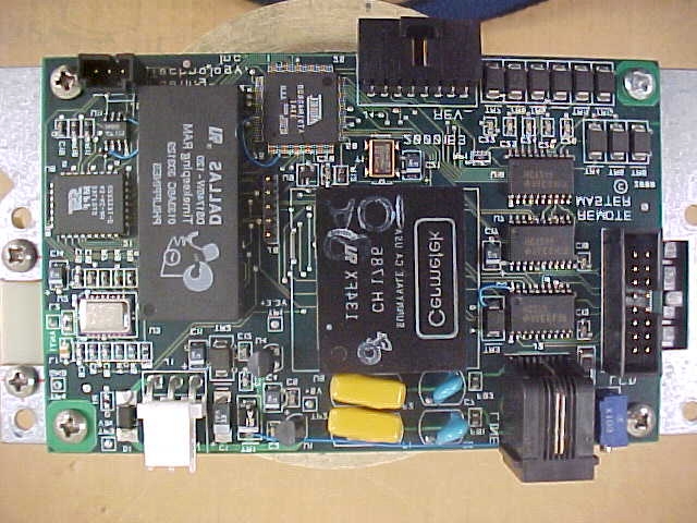
PGXM100TUTank Unit for an LPG Gauging System

Fueling Technologies, Inc.
Tank Unit for an LPG Gauging System - FCC ID PGXM100TU - Fueling Technologies, Inc.
Click to zoom

Application Details

Equipment Class
DXX - Part 15 Low Power Communication Device Transmitter
Date of Grant
Jul 10, 2002
Application Purpose
Original Equipment
Date of Application
Mar 30, 2002
Equipment Note
Tank Unit for an LPG Gauging System
Frequency Range
916.50000000 - 916.50000000
Company
Fueling Technologies, Inc.
Country
United States

Documents & Files

Select a file to view

Users Manual

↗
↗

Cover Letter(s)

↗
↗

ID Label/Location Info

↗
↗

Internal Photos

↗

Test Report

↗

Document Text

Text extracted from the exhibit documents filed with the FCC. Open a document above to read the original.

Users Manual

Copyright Fueling Technologies, Inc., 2001 All Rights Reserved INSTALLTION/USER’S MANUAL FOR FTI MODEL 100 LP GAS TANK GAUGE SYSTEM 9000100 Fueling Technologies, Inc. 13434 NE 177 th Place Woodinville, Washington 98072 425-487-3464 Installation/User’s Manual9000100 Revision Draft FTI Model 100 LP Gas Tank Gauge SystemPage 2 of 20 Copyright Fueling Technologies, Inc., 2001 All Rights Reserved TABLE OF CONTENTS REVISIONS ........................................................................................................................ 3 ATTENTION!! .................................................................................................................. 4 FCC NOTICE......................................................................................................................7 1. Introduction ................................................................................................................. 8 1.1. Scope ....................................................................................................................... 8 1.2. Damage Claims....................................................................................................... 8 1.3. Return Shipping....................................................................................................... 8 2. Product Description..................................................................................................... 8 2.1. The System .............................................................................................................. 8 2.2. The Master Computer.............................................................................................. 9 2.3. The Flange Feed Through Kit................................................................................. 9 2.4. The Hanger Assembly............................................................................................. 9 2.5. The Probe................................................................................................................ 9 2.6. The Tank Computer................................................................................................. 9 2.7. Active Repeaters................................................................................................... 10 2.8. Passive Repeaters.................................................................................................. 10 3. Abbreviations Used ................................................................................................... 10 4. Related FTI Documents............................................................................................. 10 5. Site Preparation and Planning ................................................................................... 11 5.1. Planning and Locating the Master Computer ........................................................ 11 5.2. Radio Path Planning.............................................................................................. 12 5.3. Hazardous Areas.................................................................................................... 13 5.4. The Tank................................................................................................................ 13 5.5. Battery Life........................................................................................................... 14 5.6. Tool and Material Requirements........................................................................... 14 6. Installation ................................................................................................................. 14 6.1. Tank Equipment.................................................................................................... 14 6.2. Installing Repeaters............................................................................................... 16 6.3. The Tank Computer............................................................................................... 16 6.4. The Master Computer............................................................................................ 16 6.5. Initializing the Master Computer.......................................................................... 16 7. Replacing the Battery Pack ....................................................................................... 17 8. Specifications ............................................................................................................ 18 8.1. Master Computer ................................................................................................... 18 8.2. Tank Computer...................................................................................................... 19 8.3. Hanger Assembly and Probe................................................................................. 19 9. Control Drawing........................................................................................................ 20 Installation/User’s Manual9000100 Revision Draft FTI Model 100 LP Gas Tank Gauge SystemPage 3 of 20 Copyright Fueling Technologies, Inc., 2001 All Rights Reserved REVISIONS 1. Initial Draft (Revision Draft) October 8, 2001, by RCS Installation/User’s Manual9000100 Revision Draft FTI Model 100 LP Gas Tank Gauge SystemPage 4 of 20 Copyright Fueling Technologies, Inc., 2001 All Rights Reserved ATTENTION!! READ THIS SECTION BEFORE BEGINNING INSTALLATION A portion of this product is designed for installation in a LP Gas fuel storage tank. THIS ENVIRONMENT CONTAINS HIGHLY FLAMMABLE AND HAZARDOUS MATERIALS. FOLLOW ALL INSTRUCTIONS AND WARNINGS CONTAINED IN THIS MANUAL. FAILURE TO DO SO COULD RESULT IN FIRE, EXPLOSION, AND/OR SERIOUS INJURY TO YOURSELF AND OTHERS AND DAMAGE TO PROPERTY. This product and installation guide were designed to minimize the dangers of installing this product, but you, the installer, must maintain the responsibility for proper installation to minimize the risk to li…

Text truncated - open the document above for the full version.

Users Manual

Copyright Fueling Technologies, Inc., 2001 All Rights Reserved INSTALLTION/USER’S MANUAL FOR FTI MODEL 100 LP GAS TANK GAUGE SYSTEM 9000100 Fueling Technologies, Inc. 13434 NE 177 th Place Woodinville, Washington 98072 425-487-3464 Installation/User’s Manual9000100 Revision Draft FTI Model 100 LP Gas Tank Gauge SystemPage 2 of 20 Copyright Fueling Technologies, Inc., 2001 All Rights Reserved TABLE OF CONTENTS REVISIONS ........................................................................................................................ 3 ATTENTION!! .................................................................................................................. 4 FCC NOTICE......................................................................................................................7 1. Introduction ................................................................................................................. 8 1.1. Scope ....................................................................................................................... 8 1.2. Damage Claims....................................................................................................... 8 1.3. Return Shipping....................................................................................................... 8 2. Product Description..................................................................................................... 8 2.1. The System .............................................................................................................. 8 2.2. The Master Computer.............................................................................................. 9 2.3. The Flange Feed Through Kit................................................................................. 9 2.4. The Hanger Assembly............................................................................................. 9 2.5. The Probe................................................................................................................ 9 2.6. The Tank Computer................................................................................................. 9 2.7. Active Repeaters................................................................................................... 10 2.8. Passive Repeaters.................................................................................................. 10 3. Abbreviations Used ................................................................................................... 10 4. Related FTI Documents............................................................................................. 10 5. Site Preparation and Planning ................................................................................... 11 5.1. Planning and Locating the Master Computer ........................................................ 11 5.2. Radio Path Planning.............................................................................................. 12 5.3. Hazardous Areas.................................................................................................... 13 5.4. The Tank................................................................................................................ 13 5.5. Battery Life........................................................................................................... 14 5.6. Tool and Material Requirements........................................................................... 14 6. Installation ................................................................................................................. 14 6.1. Tank Equipment.................................................................................................... 14 6.2. Installing Repeaters............................................................................................... 16 6.3. The Tank Computer............................................................................................... 16 6.4. The Master Computer............................................................................................ 16 6.5. Initializing the Master Computer.......................................................................... 16 7. Replacing the Battery Pack ....................................................................................... 17 8. Specifications ............................................................................................................ 18 8.1. Master Computer ................................................................................................... 18 8.2. Tank Computer...................................................................................................... 19 8.3. Hanger Assembly and Probe................................................................................. 19 9. Control Drawing........................................................................................................ 20 Installation/User’s Manual9000100 Revision Draft FTI Model 100 LP Gas Tank Gauge SystemPage 3 of 20 Copyright Fueling Technologies, Inc., 2001 All Rights Reserved REVISIONS 1. Initial Draft (Revision Draft) October 8, 2001, by RCS Installation/User’s Manual9000100 Revision Draft FTI Model 100 LP Gas Tank Gauge SystemPage 4 of 20 Copyright Fueling Technologies, Inc., 2001 All Rights Reserved ATTENTION!! READ THIS SECTION BEFORE BEGINNING INSTALLATION A portion of this product is designed for installation in a LP Gas fuel storage tank. THIS ENVIRONMENT CONTAINS HIGHLY FLAMMABLE AND HAZARDOUS MATERIALS. FOLLOW ALL INSTRUCTIONS AND WARNINGS CONTAINED IN THIS MANUAL. FAILURE TO DO SO COULD RESULT IN FIRE, EXPLOSION, AND/OR SERIOUS INJURY TO YOURSELF AND OTHERS AND DAMAGE TO PROPERTY. This product and installation guide were designed to minimize the dangers of installing this product, but you, the installer, must maintain the responsibility for proper installation to minimize the risk to li…

Text truncated - open the document above for the full version.

Cover Letter(s)

Fueling Technologies, Inc . Fueling Technologies, Inc. 1401 Capital Avenue Plano, Texas 75074 Telephone: 972-943-9322 Fax: 972-943-9326 May 22, 2002 Mr. Steve Dayhoff Federal Communicatio ns Co mmission 445 12th Street SW Washington, DC 20554 Re: EA235309; Ref No.: 22958 Dear Mr. Dayhoff: We are in receipt of your email of May 21, 2001, concerning our Model 100 Tank Unit (PGXM100TU). Your requests together with our responses are below. 1. Please submit Schematic Diagrams of the circuitry. Response: Schematics (three pages) have been added as attachments. 2. Please submit a Block Diagram of the circuitry. Response: A block diagram for both the Master and the Tank Unit are contained in the Theory of Operation which is submitted as an attachment. 3. Please upload internal and external photos into the proper folder of the EAS. Response: Those photos are contained in the Test Report already submitted. If these are inadequate, please let me know your requirements ASAP and I will forward additional photos. 4. You have paid for Confidential status of exhibits, however no request letter has been submitted. Please forward a letter to request certain exhibits to be held confidential in our data base. Response: That letter is attached as a cover letter. 5. Please submit a parts list. Response: A parts list for the main circuit board containing the microprocessor and radio is attached (2000152). I also attach a system User’s Manual for your information. Sincerely yours, Robert C. Scott, P.E. Vice President Fueling Technologies, Inc . - Page 2 -

Cover Letter(s)

Fueling Technologies, Inc . Fueling Technologies, Inc. 1401 Capital Avenue Plano, Texas 75074 Telephone: 972-943-9322 Fax: 972-943-9326 May 22, 2002 Federal Communicatio ns Co mmission 445 12th Street SW Washington, DC 20554 Gentlemen: Regarding our filing for FCC ID PGXM100TU, Fueling Technologies, Inc., requests all its documents permitted confidential be kept confidential. Should there be any questions, please call. Sincerely yours, Robert C. Scott, P.E. Vice President Fueling Technologies, Inc . - Page 2 -

ID Label/Location Info

Wood inville, Was hingto n Liquid Level Gauge For LP Gas Part No.: 2800027 Model 100 Tank Unit for Model 100 LPG Tank Gauge System Intrinsically Safe When Installed in Accordance With Control Drawing 4000427 Class I, Div 1, Group D Warning: Substitution of Components May Impair Intrinsic Safety Locate on Exterior Cover of Unit LISTED 9EX3 Only Use FTI Supplied Battery Assembly Part No’s 2500201-1 or -2 Temperature Code: T6 Do Not Connect Any External Wiring This device complies with part 15 of the FCC rules. Operatio n is s ubje ct to the fo llo wing two co nd itio ns : 1. This device may not cause harmful interference, and 2. This device must accept any interference that may cause undesired operation. FCC ID: PGXM100TU

ID Label/Location Info

.XXX .XX FRACTIONAL ANGULAR DECIMAL DECIMAL .010" 1° - + + - 1/32" .020" + - - + ALL DIMENSIONS ARE IN INCHES AND INCLUDE APPLIED FINISH. REMOVE ALL BURRS AND SHARP EDGES. CONCENTRICITY ON MACHINED DIAMETERS .010 FIM. - + DECIMAL HOLE DIAMETERS .013 THRU .250 .251 THRU 1.000 + - - + .003" .005" TOLERANCES UNLESS OTHERWISE SPECIFIED SCALE: DRAWN: DATE: APP'D: RELEASED: MATERIAL: JOB NO. REV. DRAWING NO. TITLE: SHEET CUSTOMER: K STEPHENS DRAWING NO. REV. C The Jamesport Group ------------------- 1/19/01 Remote Assembly LPG Tank Level Monitor 2800027 C A Initial Release KES 1/19/01 B Assy Conponent Changes 1-S 4 1-T 1 9 4 7 1 4 2 2 1 1-B 1 6 1 1" = 2" NOTES: 1) USE DRAWING AND BOM FOR ITEM # REFERENCE,ORIENTATION AND QUANTITIES. COPYRIGHT 2001 FUELING TECHNOLOGY, INC. EXAMPLE: 4 2 ITEM # 4 SCREWS QTY OF 2. 2) USE DOCUMENT # 2800027.DOC FOR ASSEMBLY NOTES. C New Battery Pack Layout and updates INSTALL CAP OVER MOUNTING SCREW 1-C 2 KES LSH 8/14/01 3/7/02 Front View with cover on 10 1 3 1 Bill of Materials Printed 4/25/02 ItemQtyPart NumberTypeTitleReference VendorVendor P/NMfr NameMfr P/N 2800027 FTI, REMOTE PROPANE PROBE CONTROLER Type Status Revision PL U B User 1 User 2 Date ByLSH UnitRevDetail 11 each 2500199 DWG B FTI, REMOTE PROPANE ENCLOSURE NEMA 4X, BASE, TOP, CAPS AND SCREWS ALLIED ELECTRONICSALTECH125-904 ENCLOSURE IS A COMPLETE SET. BASE PART MUST BE MACHINED. 21 each 2700086 PL B REMOTE PROBE ELECTRONICS ASSEMBLY FTI PLTS ASSURED INDUSTRIES 31 each 0080302 DWG B BRACKET, REMOTE MOUNTING Ammon & Rizos 42 each 0085354 PS SCREW, PHILLIPS PAN HEAD (PPH) #8 X 3/8, FAST THREAD FOR PLASTIC 61 each 2500187 DWG C CABLE GLAND ASSEMBLY, REMOTE PROPANE FTI 71 each 0080315 PS A BRACKET, CABLE COVER TANK LEVEL MONITOR, FTI Ammon & Rizos 94 each 0085209 PS SCREW, HEX HEAD, THREAD ROLLING TAP TIGHT OR EQUIV, 8-32 X 3/8 101 each 0071114 DWG LABEL, SPEC PLATE FTI REMOTE TANK The Jamesport Group 1401 Capital Ave., Plano Texas 75074 972-943-9322 Fax 972-943-9326 2800027 1Page 1 of

Internal Photos

Front View of Equipment Under Test Close Look at the front EUT Model 1000152 Rev. A Close Look at the rear EUT Model 1000152 Rev. A Close look at the Front Liquid Crystal Display Model NDM20216L-1-L30S Close look at the Rear Liquid Crystal Display Model NDM20216L-1-L30S

Test Report

NTS Test Report No. B2819 TANK-FCC Page 1 of 20 National 1701 E. Plano Pkwy Suite 150 Technical Plano, TX 75074 Systems Tel: 972-509-2566 Fax: 972-509-0073 Electromagnetic Compatibility (EMC) For FUELING TECHNOLOGIES, INC. TANK UNIT FCC PART 15, SUB-PART B, CLASS A and FCC PART 15.249, SUB-PART C Prepared For: FUELING TECHNOLOGIES, INC. 13434 177 th Place Woodinville, WA 98072 Prepared By: National Technical Systems 1701E. Plano Parkway Suit 150 Plano, TX 75074 Issued: March 2002 This report and the information contained herein represent the results of testing test articles identified and selected by the client performed to specifications and/or procedures selected by the client. National Technical Systems (NTS) makes no representations, expressed or implied, that such testing is adequate (or inadequate) to demonstrate efficiency, performance, reliability, or any other characteristic of the articles being tested, or similar products. This report should not be relied upon as an endorsement or certification by NTS of the equipment tested, nor does it represent any statement whatsoever as to its merchantability or fitness of the test article, or similar products, for a particular purpose. This report shall not be reproduced except in full.  NTS Test Report No. B2819 Tank-FCC National Technical Systems, Electromagnetic Compatibility Test Report Page 2 of 23 1701 E. Plano Parkway Suite 150, Plano, TX 75074; Tel (972) 509-2566; Fax (972) 509-0073 Service For: FUELING TECHNOLOGIES, INC. Purchase Order No.: 20020301 & 2001121701 This is to certify that the following report is true and correct to the best of my knowledge. ________________________________ _______________________________ Dieu Vo, Trudy Hester EMI Operations Supervisor Quality Assurance Manager FCC, CE, Telecommunication  NTS Test Report No. B2819 Tank-FCC National Technical Systems, Electromagnetic Compatibility Test Report Page 3 of 23 1701 E. Plano Parkway Suite 150, Plano, TX 75074; Tel (972) 509-2566; Fax (972) 509-0073 TABLE OF CONTENTS 1.0 GENERAL INFORMATION...................................................................................................................5 1.1 PRODUCT DESCRIPTION.....................................................................................................................5 1.2 SUPPORT DETAILS.................................................................ERROR! BOOKMARK NOT DEFINED. 1.3 INSTRUMENT CALIBRATION.............................................................................................................6 1.3.1 ACCURACY OF MEASUREMENT....................................................................................................7 1.4 AMBIENT TESTS....................................................................................................................................7 1.5 FAILURE REPORTING..........................................................................................................................7 1.6 THRESHOLD OF SUSCEPTIBILITY....................................................................................................7 1.7 TEST PROGRAM DEVIATION.............................................................................................................8 1.8 INSPECTION...........................................................................................................................................8 1.9 DISPOSITION OF TEST ITEMS............................................................................................................8 1.10 TEST FACILITY......................................................................................................................................8 2.0 GENERAL TEST METHODOLOGY.....................................................................................................9 2.1 EMISSIONS..............................................................................................................................................9 2.1.1 RADIATED EMISSIONS FIELD STRENGTH CALCULATIONS.................................................10 2.2 ORDER OF TESTING...........................................................................................................................10 2.3 SPECIAL TEST JUSTIFICATION.......................................................................................................10 3.0 TEST CONFIGURATION.....................................................................................................................11 3.1 SELECTION OF FUELING TECHNOLOGIES, INC.’ TANK UNIT CONFIGURATION AND MODES OF OPERATION................................................................................................................................11 3.2 EQUIPMENT MODIFICATIONS.........................................................................................................11 4.0 TEST INSTRUMENTATION................................................................................................................12 5.0 EMISSIONS............................................................................................................................................13 5.1 RADIATED EMISSIONS.......................................................................................................................13 5.1.1 RADIATED EMISSIONS TEST SETUP...........................................................................................13  NTS Test Report No. B2819 Tank-FCC National Technical Systems, Electromagnetic Compatibility Test Report Page 4 of 23 1701 E. Plano Parkway Suite 150, Plano, TX 75074; Tel (972) 509-2566; Fax (972) 509-0073 5.1.2 RADIATED MEASUREMENT DATA..............................................................................................17 5.13 RADIATED MEASUREMENT CFR 47 FCC PART 15.249 SUBPART C..........................................20 5.2 CONDUCTED EMISSIONS......................................................ERROR! BOOKMARK NOT DEFINED. 5…

Text truncated - open the document above for the full version.

Contact Information

Applicant

Robert C Scott(Vice President)
[email protected]9729439322Fax: 9729439322

Test Firm

National Technical Systems (NTS)John Ngo
[email protected]972-509-2566Fax: 972-509-0073

Technical Specifications

#Rule PartsFrequency RangePower Output
115C916.5 MHz - 916.5 MHz-
Confidentiality
Long Term

Other Applications from Fueling Technologies, Inc.
Master Computer for LPG Tank Gauge System - FCC ID PGXM100MC - Fueling Technologies, Inc.
PGXM100MC

Master Computer for LPG Tank Gauge System

Jul 10, 2002

Equipment Class

DXX - Part 15 Low Power Communication Device Transmitter