PH29402Glucose Monitoring System
Dexcom, Inc.
Click to zoom
Application Details
- Equipment Class
- TNT - Licensed Non-Broadcast Transmitter Worn on Body
- Date of Grant
- Sep 18, 2006
- Application Purpose
- Original Equipment
- Date of Application
- Aug 14, 2006
- Equipment Note
- Glucose Monitoring System
- Frequency Range
- 402.14200000 - 402.14200000
- Company
- Dexcom, Inc.
- Country
- United States
Documents & Files
Document Text
Text extracted from the exhibit documents filed with the FCC. Open a document above to read the original.
Users Manual
DexCom™ STS™-7 CoNTINUoUS GLUCoSe moNIT oRING SYSTem STS TM -7 Sensor & STS TM Applicator STS TM -7 Sensor & STS TM T2 Transmitter STS TM R2 Receiver www.DexCom.com wa RNING Treatment decisions should not be based solely on results from the DexCom STS-7 System. You must confirm with a blood glucose meter before making therapeutic adjust- ments. *MAKE SURE YOUR STS R2 RECEIVER IS CHARGED BEFORE YOU BEGIN. STaRTING CoNTINUoUS GLUCoSe moNIToRING ST eP 1 INS eRTING a N ew STS™ -7 SeNS oR Choose a site on your abdomen (belly) to put the STS-7 Sensor that is a flat area and where you don’t have any scarring or rough patches of skin and clean the site with an alcohol swab. 1. Remove the adhesive backing from the STS Sensor Pod and place the STS-7 Sensor on the selected site. Pull the safety lock out from the STS Applicator (pull near the ar- row). 2. Place 2 fingers under the collar, with your thumb on the plunger, and push the plunger down completely. 3. Pull the collar back completely until you hear a click. 4. Press the tabs on the sides of the STS-7 Sensor and pull off the STS Applicator. 5. The STS Sensor Pod remains adhered to the skin after the STS Applicator is removed. Install STS-7 Transmitter in STS Sensor Pod STS-7 Transmitter Installed STS Transmitter Latch Remove STS Transmitter Latch 213 Place the STS T2 Transmitter into the STS Sensor Pod with the flat side facing down. Pull the STS Transmitter Latch up onto the STS T2 Transmitter to snap it into place. Remove the STS Transmitter Latch by holding the end of the latch and quickly twisting off the latch away from your body. 1. 2. 3. Press any buttons on the STS R2 Receiver to check for the Antenna Icon (Y) at the bottom right hand corner of the screen. If 4. STeP 2 INST aLLING Yo UR STS™ T2 TRaNS mITT eR 1. Dual Blood Drop Prompt: After 2 hours the STS R2 Receiver will vibrate and dis- play the Dual Blood Drop Prompt to alert you to calibrate the STS-7 Sensor. Press the C Button to clear the prompt. the Antenna Icon appears in the upper right hand corner of the screen, refer to your User’s Guide Press the Down q Arrow 3 times until you come to the 9-hour Glucose Trend Screen. Then hold the Down q Arrow for at least 7 seconds until you see the STS License Code Screen (If you have already inserted a STS-7 Sensor, press the Down q Arrow 1 more time to get to the STS License Code Screen): 1. Press the OK button. The antenna (Y) should appear here Use the Up p and Down q Arrows to enter the STS License Code found in your shipment and press the OK button to confirm the STS License Code. 2. STeP 4 how To ST aRT Y oUR CoNTINUoUS GLUCoSe moNIToRING SeSSI oN STeP 3 eNT eRING a STS LIC eNS e CoDe STeP 5 Ca LI bRaTING YoUR STS ™-7 SYSTem 2. Meter Connection Screen: After you take 2 fingersticks using your blood glucose me- ter, upload the values to your STS R2 Re- ceiver. Upload the meter values to the STS R2 Receiver by plugging the connection cable into the meter first (the meter must be off) and then into the STS R2 Receiver. The Meter Connection Screen (“PC”) will appear on your blood glucose meter. 1. Dual Blood Drop Prompt 2. Meter Connection Screen MC 1. Press the Down q Arrow 3 times until you come to the 9-hour Glucose Trend Screen. Then hold the Down q Arrow for at least 7 seconds until you see the STS Sensor In- sertion Screen (If you have already entered a STS License Code). 2. Press the OK button to confirm Sensor Insertion and you will see the following Confirmation Screen:. 3. Your Start-Up Period begins once you press the OK button. Technical Support at 1-877-(Dex Com 4) 339-2664. Confidential Transmitter model number 9400-02 Draft Under FDA Review Safety LockPush PlungerPull Collar Collar Completely Back Remove STS Applicator 21345 Press Tabs STS Sensor Pod Remains Adhered The error code indicates the STS R2 Re- ceiver is not functioning properly. Note the Error code, use your meter to check your blood glucose readings, and contact Dex- com Technical Support at 1-877-DEXCOM4 (339-2664) immediately. Your Continuous Glucose Monitoring Session is finished and you should remove the STS-7 Sensor. © DexCom 2006 All rights reserved STS™-7 SeNS oR exPIR aTI oN No TI fIC aTI oN eRR oR CoDe The STS R2 Receiver will display screens that notify you how long you have until the end of your Continuous Glucose Monitor- ing Session. You will be notified at 6 hours, 2 hours, 30 minutes before your session ends, and when your session is finished. 30 minute STS Sensor Expiration Notification 0 hour STS Sensor Expiration Notification 2 hour STS Sensor Expiration Notification 6 hour STS Sensor Expiration Notification eNDING YoUR CoNTINUoUS GLUCoSe moNIToRING SeSSI oN 3. Receiver Connection Screen 3. Receiver Connection Screen: The Receiver Connection Screen will appear on the STS R2 Receiver while the BG values are being transferred from the meter to the STS R2 Receiver. 4. 1-Hour Trend Screen 4. 1-Hour Trend Screen: Once the upload is complete the 1-Hour Trend Screen will appear. Disconnect the cable from the meter and STS R2 Receiver. A glucose value should appear in about 15 minutes and glucose values will be updated every 5 minutes. STeP 5 Ca LI bRaTING YoUR STS ™-7 SYSTem ( CoNTINUeD) 3. Shaded-Out Blood Drop Prompt New Meter Screen: Indicates that you have connected a new meter to the STS R2 Receiver. Press OK. You must re-take the fingersticks and connect the meter to the STS R2 Receiver. Connection Failure Screen: Indicates the meter and STS R2 Receiver are not con- nected properly. If you see this screen the meter values will not be transferred successfully. Clear the alert by pressing 1. 2. 1. New Meter Screen 2. Connection Failure Screen any button and disconnect the cable from the STS Receiver. Make sure the meter is off and reconnect the cable to the STS R2 Receiver (the cable must be plugged into the meter first). Shaded-Out Blood Drop Prompt: Notifies you that 1 more fingerstick is needed for calibration. Take another fingerstick an…
Text truncated - open the document above for the full version.
Attestation Statements
Federal Communications Commission FCC 06-1 Before the Federal Communications Commission Washington, D.C. 20554 In the Matter of DexCom, Inc . Request for Waiver of the Frequency Monitoring Requirements for the Medical Implant Communications Service Rules ) ) ) ) ) ) ) ) ET Docket No. 05-213 ORDER Adopted: January 12, 2006 Released: January 18, 2006 By the Commission: I. INTRODUCTION 1. By this Order, we grant a request for waiver filed by DexCom, Inc., 1 authorizing it to build and market its blood glucose monitoring system to operate in the Medical Implant Communications Service (MICS) band. 2 This waiver is granted for a period of three years, or until such time as the Commission amends its rules related to such devices to obviate the need for a waiver or to specify rules with which devices of this kind will be required to comply. 2. The DexCom STS (short-term) and LTS (long-term) blood glucose monitoring sensors are devices implanted into the body that combine a monitor with a low-power transmitter to provide frequent, periodic information regarding blood glucose levels. These monitor readings are transmitted to a receiver worn by a diabetic patient, so that the patient can continuously monitor his/her blood glucose level and take nutrition or medication (insulin) as necessary to maintain an appropriate glucose level in the blood. They can also send an alarm to the wearer when the blood glucose level falls outside acceptable levels. The devices operate on a single channel, and do not have a “listen before talk” (LBT) capability nor are they frequency agile, as required by the MICS rules. 3 Consequently, DexCom requests a waiver of these rules to permit it to manufacture and market, and for medical professionals to prescribe and diabetic patients to use, the STS and LTS as currently configured. 3. Opposition was filed by Medtronic, Inc. (Medtronic), the developer of a variety of medical implant devices, including implanted monitoring and communications devices for cardiac patients that comply fully with the MICS rules. 4 Comments supporting DexCom’s request were filed by the Juvenile Diabetes Research Foundation (JDRF); Biotronik, a maker of other implantable medical 1 Public Notice, June 15, 2005, DA 05-1670. 2 MICS operates at 402-405 MHz, and is governed by Part 95, Subpart I of the Commission’s rules (47 C.F.R §§ 95.1201ff; also 47 C.F.R. § 95.628). 3 47 C.F.R. § 95.1211. 4 Meditronic also makes insulin pumps and a monitor for diabetics that communicate on non-MICS frequencies. Federal Communications Commission FCC 06-1 2 devices with transmitters; and AMI Semiconductors, Inc. (AMI), a provider of integrated circuits to the medical industry. II. BACKGROUND 4. In 1999, the Commission established the MICS rules to allow the operation of radio transmitters that support the diagnostic and/or therapeutic functions associated with implanted medical devices to enable individuals and medical practitioners to utilize potential life-saving medical technology without causing interference to other users of the spectrum. 5 The Commission determined that the 402- 405 MHz band is particularly well suited for this service, due to the signal propagation characteristics in the human body, the relative dearth of other users of the band, the compatibility of the MICS service with the incumbent users of the band, and its use internationally for this purpose. 6 To avoid harming other users of the frequency band, MICS was provided a secondary allocation. The 402-405 MHz band was, and remains, allocated on a primary basis to Federal Government uses, including Meteorological Aids Service (Metaids), the Meteorological Satellite Service, and the Earth Exploration Satellite Service. 7 The Commission adopted technical rules for the MICS specifically designed to protect these incumbent Federal services, as well as to ensure compatibility among multiple MICS devices and users. 8 These rules establish a channel bandwidth of 300 kHz for this service within the allotted bandwidth, 9 provide for frequency sharing and cooperation in the selection and use of channels, 10 and establish specific guidelines for frequency monitoring prior to transmission by implant programmer/control transmitters. 11 12 Given these protections, the National Telecommunications and Information Administration (NTIA), representing the incumbent Federal user entitled to exclusive use of this band, interposed no objection to this allocation. 13 5. In 2003, the Commission found that another implanted medical device (a cardiac pacemaker with a transmitter for monitoring data concerning the heart) that operates similarly to the subject devices – at very low power with periodic, brief transmissions in the MICS band, lacking a listen- before-talk function and frequency agility – did not comply with the Commission’s rules when sending 5 Report and Order in WT Docket No. 99-66 (Amendment of Parts 2 and 95 of the Commission’s Rules to Establish a Medical Implant Communications Service in the 402-405 MHz Band) (“MICS Order”), 14 FCC Rcd, 21040 (1999). 6 Id. at 21042-43. 7 In this band, Metaids currently operates radiosondes, which are automatic transmitters, usually carried on an aircraft, free balloon, kite, or parachute, which transmit meteorological data during their journey through the atmosphere. (See 47 C.F.R. § 2.1.) 8 Id. at 21046. 9 47 C.F.R. § 95.628(c), (d). 10 47 C.F.R. § 95.1211. 11 47 C.F.R. § 95.625(a). 12 The Commission also provided that a MICS device could transmit without prior frequency monitoring, pursuant to a non-radio frequency actuation signal generated by a device external to the body (manual activation) (47 C.F.R. § 95.1209(b)), or in response to a medical implant event (47 C.F.R. §§ 95.628(b), 95.1209(b)). These functions are not the subject of the instant waiver request. 13 NTIA is responsible for managing the Government portion of the Table of Frequency Allocations. In bands shared between Federal and non-Federal Government…
Text truncated - open the document above for the full version.
ID Label/Location Info
STS Transmitter Equipment Identification Label (Bottom Side Of Transmitter) Label is physically engraved into the bottom of each STS Transmitter
Test Report
Report No. SC602042-08 Page 1 of 7 Rev.No 1.0 TÜV AMERICA INC 10040 Mesa Rim Road San Diego, CA 92121-2912 Phone 858 678 1400 FAX 858 546 0364 EMC - TEST REPORT UNITED STATES STANDARD FCC PART 95 Test Report File No. : SC602042-08 Date of Issue: 18 April 2006 Model / Serial No. : 9400-02 / -- Product Type : STS Transmitter Applicant : DEXCOM INCORPORATED Manufacturer : DEXCOM INCORPORATED License holder : DEXCOM INCORPORATED Address : 5555 Oberlin Drive : San Diego, CA 92121 Test Result : Positive Negative Test Project Number Reference(s) : SC602042-08 Total pages - Test Report : 30 NOTE: All test equipment used during testing is calibrated and traceable to NIST. TÜV America reports apply only to the specific sample tested under stated test conditions. It is the manufacturer’s responsibility to assure the continued compliance of production units of this model. TÜV America, Inc. shall have no liability for any deductions, inferences or generalizations drawn by the client or others from TÜV America, Inc. issued reports. This report is the confidential property of the client. As a mutual protection to our clients, the public and ourselves, extracts from the test report shall not be reproduced except in full without our written approval. This report shall not be used by the client to claim product endorsement by NVLAP or any agency of the US government. TÜV America, Inc. and its professional staff hold government and professional organization certifications and are members of AAMI, ACIL, AEA, ANSI, IEEE, NVLAP, and VCCI Report No. SC602042-08 Page 2 of 7 Rev.No 1.0 TÜV AMERICA INC 10040 Mesa Rim Road San Diego, CA 92121-2912 Phone 858 678 1400 FAX 858 546 0364 DIRECTORY Test Report Pages Test Report 1 - 7 Directory 2 Test Regulations 3 General Remarks and Summary 7 Equipment Frequency Stability Emission Bandwidth Radiated Spurious Emissions Unintentional within Band (402-405 MHz) Low Band Edge High Band Edge Maximum Transmitter Power 5 Technical Documentation Test Data Sheets and Test Setup Drawing(s) TD1 Appendices Appendix A - Test Setups (Photographs) A1 Appendix B - Product Information Form(s) B1 Appendix C - Change History C1 Appendix D - Supplemental Information D1 Report No. SC602042-08 Page 3 of 7 Rev.No 1.0 TÜV AMERICA INC 10040 Mesa Rim Road San Diego, CA 92121-2912 Phone 858 678 1400 FAX 858 546 0364 TEST REGULATIONS: The tests were performed according to the following regulations: - EN 50081-1: 1991 - EN 55011: 1998, Amendment A2: 2002 - Group 1 - Group 2 - Class A - Class B - EN 55013: 1990 - EN 55014: 1993 - Household appliances and similar - Portable tools - Semiconductor devices - EN 55022: 1987 - Class A - Class B - EN 55022: 1998, Amendment A2: 2003 - Class A - Class B - VCCI - Class A ITE - Class B ITE - CNS 13438: 1994 - Class A - Class B - FCC Part 95 - AS/NZS 3548: 1995 - Class A - Class B - CISPR 11: 1997 - Group 1 - Group 2 - Class A - Class B - CISPR 22: 1997 - Class A - Class B Report No. SC602042-08 Page 4 of 7 Rev.No 1.0 TÜV AMERICA INC 10040 Mesa Rim Road San Diego, CA 92121-2912 Phone 858 678 1400 FAX 858 546 0364 Environmental Conditions In The Laboratory: Actual Temperature : 23 °C Relative Humidity : 50 % Atmospheric Pressure : 100.0 kPa Power Supply Utilized: Power supply system : Battery Operated Symbol Definitions: - Applicable - Not Applicable Report No. SC602042-08 Page 5 of 7 Rev.No 1.0 TÜV AMERICA INC 10040 Mesa Rim Road San Diego, CA 92121-2912 Phone 858 678 1400 FAX 858 546 0364 Test Conditions: FCC Part 95, Paragraph 95.628(e) - Frequency Stability FCC Part 95, Paragraph 95.633(e)(1) - Emission Bandwidth FCC Part 95, Paragraph 95.635(d)(1) - Radiated Spurious Emissions FCC Part 95, Paragraph 95.636(d)(4) - Unintentional within Band (402-405 MHz) FCC Part 95, Paragraph 95.636(d)(5) - Low Band Edge FCC Part 95, Paragraph 95.636(d)(5) - High Band Edge FCC Part 95, Paragraph 95.639(f)(1) - Maximum Transmitter Power The measurements were performed in the following locations at the San Diego Testing Facility: - Test not applicable - TR-2, Test Room, 16’ x 10’ x 9’ - SR-3, Shielded Room, 12’ x 20’ x 8’, Metal Chamber - Roof (Small Open Area Test Site) Test Equipment Used: Model No. Prop. No. Description Manufacturer Serial No. Date Cal’ed E4446A 6823 Spectrum Analyzer Agilent US44300486 04/05 E4440A 6814 Spectrum Analyzer Hewlett Packard MY42510441 02/06 T30RC 6225 Environmental Chamber Tenney Environmental 27244-02 05/05 E3612A 6456 DC Power Supply Hewlett Packard KR83006892 N/A 34401A 6709 Digital Volt Meter Hewlett Packard 3146A03945 07/05 8648C 6586 Signal Generator Hewlett Packard 3642U01074 12/05 7405 6437 Near-Field Probe EMCO 9812-4261 N/A 8566B 6522 Spectrum Analyzer Hewlett Packard 2304A04531 04/05 3146 6641 Log Periodic Antenna EMCO 106X 06/05 3115 6669 Double Ridge Antenna EMCO 9412-4364 08/05 CBL 6111 6527 Bilog Antenna Chase Electronics -- 08/05 Remarks: One year calibration cycle for all test equipment and sites. Report No. SC602042-08 Page 6 of 7 Rev.No 1.0 TÜV AMERICA INC 10040 Mesa Rim Road San Diego, CA 92121-2912 Phone 858 678 1400 FAX 858 546 0364 Equipment Under Test (EUT) Test Operation Mode: The equipment under test was operated under the following conditions during testing: - Standby - Test Program (H - Pattern) - Test Program (Color Bar) - Test Program (Customer Specified) - Practice Operation - Normal Operating Mode - Configuration of the equipment under test: - See Constructional Data Form in Appendix B - See Product Information Form(s) in Appendix B The following peripheral devices and interface cables were connected during the testing: - Type: - Type: - Type: - Type: - Type: - Type: - Unshielded power cable - Unshielded cables - Shielded cables MPS. No.: - Customer specific cables - - Report No. SC602042-08 GENERAL REMARKS: NOTE: All photographs are representative of setup for maximum emissions. SUMMA…
Text truncated - open the document above for the full version.
Contact Information
Applicant
Vivian Wu(Staff Quality Compliance Engineer)
Test Firm
TUV America Inc.Jim Owen
Technical Specifications
| # | Rule Parts | Frequency Range | Power Output | Emission | Tolerance |
|---|---|---|---|---|---|
| 1 | 95I | 402.142 MHz - 402.142 MHz | 7.80 µW | 100KA1D | 100.0000000000 ppm |
Other Applications from Dexcom, Inc.
PH29799
May 22, 2026G7 Transmitter
Equipment Class
DTS - Digital Transmission System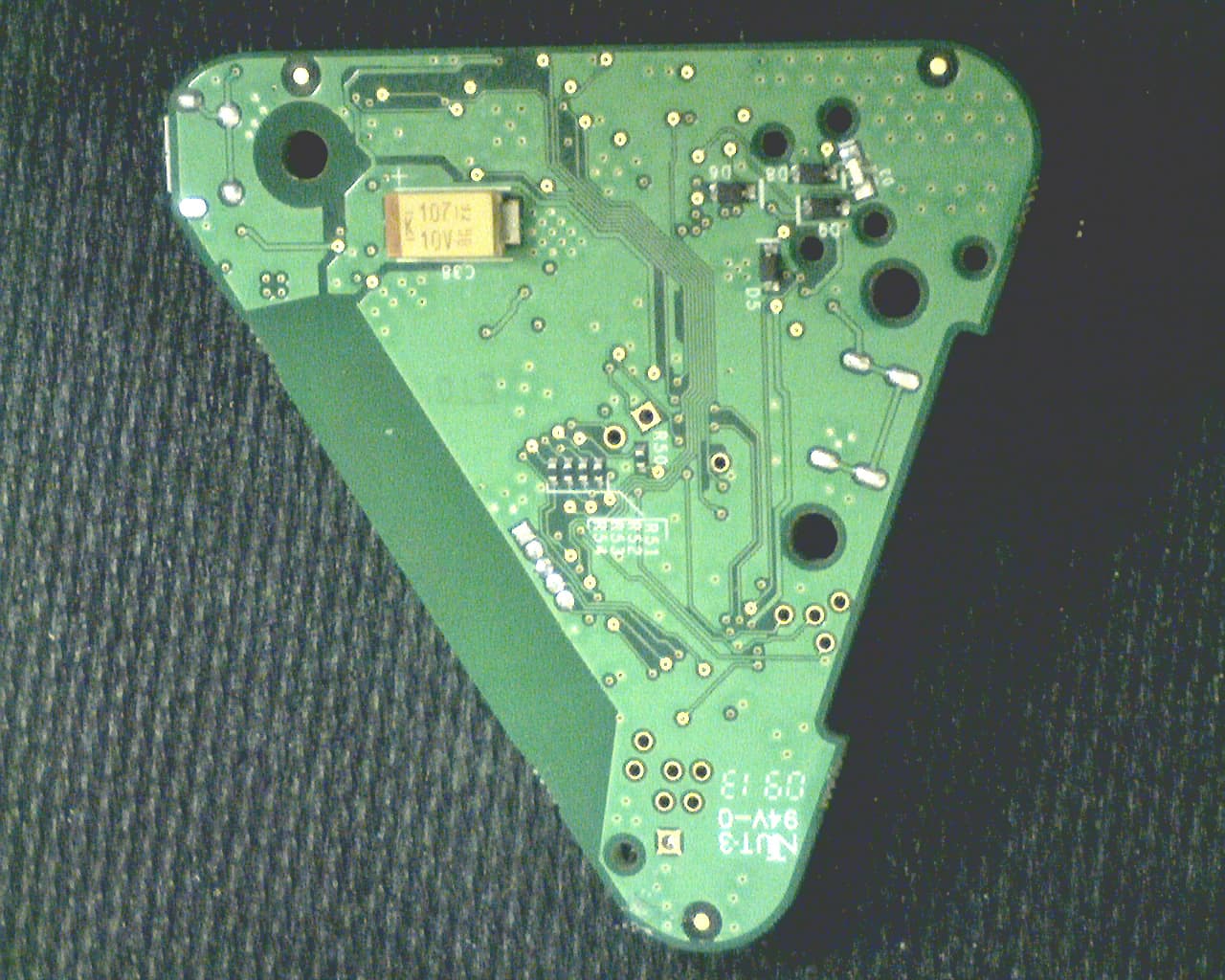
PH29006
Jul 11, 2013Dexcom Share Cradle
Equipment Class
DXX - Part 15 Low Power Communication Device Transmitter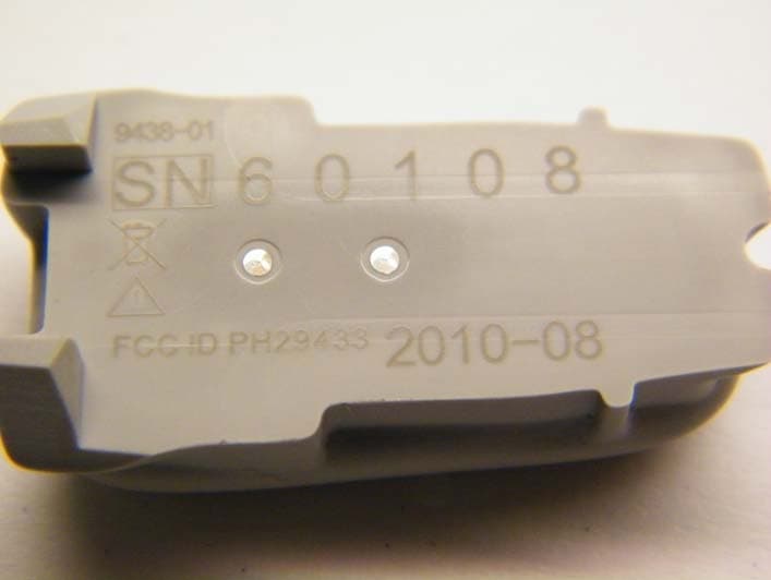
PH29433
Nov 08, 2010Glucose Monitor
Equipment Class
DXX - Part 15 Low Power Communication Device Transmitter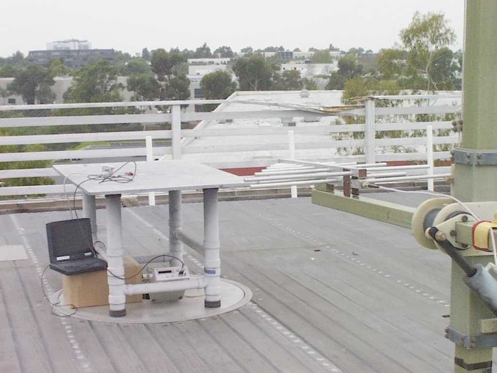
PH29400
Mar 26, 2006Glucose Monitoring System
Equipment Class
TNT - Licensed Non-Broadcast Transmitter Worn on Body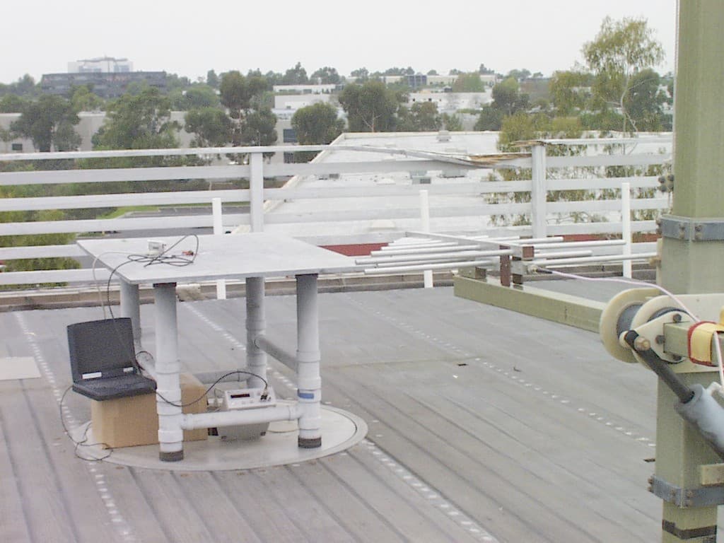
PH29300
Mar 26, 2006Glucose Monitoring System
Equipment Class
TNT - Licensed Non-Broadcast Transmitter Worn on Body