PHM-SM-500Wireless Water Level Control Device
Cazen Enterprises LLC
Click to zoom
Application Details
- Equipment Class
- DXX - Part 15 Low Power Communication Device Transmitter
- Date of Grant
- Apr 05, 2001
- Application Purpose
- Original Equipment
- Date of Application
- Apr 05, 2001
- Equipment Note
- Wireless Water Level Control Device
- Frequency Range
- 433.90000000 - 433.90000000
- Company
- Cazen Enterprises LLC
- Country
- United States
Documents & Files
Document Text
Text extracted from the exhibit documents filed with the FCC. Open a document above to read the original.
Users Manual
INSTRUCTIONS & INFORMATION U.S. AND FOREIGN PATENTS PENDING Congratulations on your Smartmiser purchase. To ensure proper installation, please read these instructions completely before installing your Smartmiser. 1.0 Mounting and Connecting the Receiver: While the Receiver unit is weather resistant, it is not waterproof. Therefore, you should choose a flat surface in a weather-protected area to install the Receiver. Depending on obstructions between the units, the Receiver is designed to receive a radio transmission up to 40 feet from the Transmitter. As the most common installation location for the Transmitter is in the pool skimmer, (See Section 3) you will get optimum performance from the Smartmiser if the Receiver is located within 35 feet of your skimmer and is at least 4.5 feet above the ground. Higher placement will improve reception. Remove the cover of the Receiver. Using the at- tachment screws provided, mount the Receiver on to the protected flat surface using the two openings on the top and bottom of the Receiver. Bend the dipole antennae down towards the ground. (See Figure 1) ™ COPYRIGHT 2000 POOLMISERPAGE 1 Figure 1 Mounting Holes PGM Wire Slots Valve 24 VAC LED Light Antennae Dipole Antennae PAGE 8COPYRIGHT 2000 POOLMISER 110 Volt GFI 24 VoltTransformer RECEIVER SKIMMER TRANSMITTER Pool Water Line to Pool SprinklerValve Radio Signal Figure 5 We recommend that you use a weather protected 110-volt GFI outlet for the Transformer. Using a portion of the 30 feet of 2 conductor wire provided, attach 2 wires to the connections on the Transformer and attach those 2 wires to the terminals on the Receiver marked 24 VAC as shown in Figure 1. Plug in the Transformer. Press the wires into the wire slots in the Receiver as shown in Figure 1. The LED light on the Receiver will flash in a series of 4 short bursts which means the Receiver will automatically shut off the water to the pool after 2 hours. See Section 5.3 for more details. 2.0 Hooking up the Gate Valve: It is now time to hook up the Receiver to a valve to fill the pool. For this function, you will need to purchase a standard 24-volt sprinkler valve that can be purchased at most plumbing and hardware stores, directly from Poolmiser, or your local Poolmiser distributor. If your pool is already plumbed with water, install the valve per manufacturer’s instructions into the existing water line. Using the wire provided, connect two of the wires to the terminals in the Receiver marked “valve” as shown in Figure 1. Press the 2 wires into the wire slots as shown. Use the wire nuts to attach the wires to the valve. If you need additional wire, make sure to use 18-gauge wire rated for exterior and underground use, which can be purchased from Poolmiser. If water is not plumbed to your pool, you will need to have a water line installed. (See Figure 5) 3.0 Positioning the Transmitter: The Transmitter has two easily identifiable ledges which will help you position the Transmitter in your pool. The top ledge is the approximate high water PAGE 2COPYRIGHT 2000 POOLMISERCOPYRIGHT 2000 POOLMISERPAGE 7 Figure 2 Top Ledge High Water Mark Low Water Mark Bottom Ledge mark and the bottom ledge is the approximate low water mark. (See Figure 2) Depending on the water level of your pool, you will attach the Transmitter either higher or lower in the water between these 2 ledges. If the water level is at or near its low point at time of installation, then the Transmitter should be installed with the bottom ledge slightly out of the water. If the water level is at or near its high point at the time of installation, the Transmitter should be installed with the top ledge slightly below the water. 4. The signal is sent and received butPossibly a problem with the valve. Re- the water does not turn on.check wiring and connections from the Receiver unit to the valve. Check the solenoid on the top of the valve and replace if necessary. 5. Water shuts off before the poolPossible that automatic shut off function is level reaches the high waterset for a smaller pool. Reset the automatic indicator on the Transmitter.shut off function in the Receiver to a longer time interval per Section 5.0. For all other problems, either contact your pool installer or contact Poolmiser directly and speak to one of our technicians. 307 Sixth Street Petaluma, CA 94952 Tel. (707) 763-7613 Fax (707) 763-0353 8.0 FCC Information: This device complies with Part 15 of the FCC Rules. Operation is subject to the following two conditions: (1) this device may not cause harmful interference, and (2) this device must accept any interference received, including interference that may cause undesired operation. This equipment has been tested and found to comply with the limits for a Class B digital device, pursuant to Part 15 of the FCC Rules. These limits are designed to provide reasonable protection against harmful interference in a residential installation. This equipment generates, uses and can radiate radio frequency energy and, if not in- stalled and used in accordance with the instructions, may cause harmful interference to radio communications. However, there is no guarantee that interference will not occur in a particular installation. If this equipment does cause harmful interference to radio or television reception, which can be determined by turning the equipment off and on, the user is encouraged to try to correct the interference by one or more of the following measures: ∑Reorient or relocate the receiving antenna. ∑Increase the separation between the equipment and receiver. ∑Connect the equipment into an outlet on a circuit different from that to which the receiver is connected. Consult the dealer or an experienced radio technician for help. PAGE 6COPYRIGHT 2000 POOLMISERCOPYRIGHT 2000 POOLMISERPAGE 3 Figure 3 Velcro Skimmer To p Water Level Attach Velcro Here 1234567890 1234567890 1 234567890 1234567890 1234567890 t 1234567890 1234567890 1234567890 1234567890 Transmitter antennae is…
Text truncated - open the document above for the full version.
Cover Letter(s)
Federal Communications Commission 7435 Oakland Mills Road Columbia, MD 21046 Gentlemen: This letter is to comply with Section 0.457(d)(2) pertaining to confidential material. Cazden Enterprises, LLC would like the following documents regarding this submission for FCC ID: PHM-SM-500 to be kept confidential. 1. Page 1 of 1 of block diagram (Cazden Enterprises) Smart Miser SM-500 Transmitter titled: “Pool Miser Transmitter Block Diagram” 2. Page 1 of 1 of Masterwork Electronics Schematics titled: Smart Miser (Transmitter Part) 3. Pages 2 of 2 of “Description of Smartmiser Transmitter RF Circuit”. The above material contains trade secrets or technical data, which would customarily be guarded from competitors. We do not want these documents to be accessible to the general public. Sincerely, Joyce Walker Report Department Manager CKC Laboratories, Inc. Agent for Cazden Enterprises, LLC
Cover Letter(s)
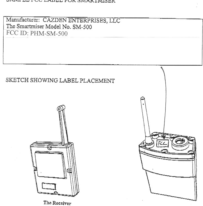
April 9, 2001 Federal Communications Commission 7435 Oakland Mills Road Columbia, MD 21046 Re:Cazden Enterprises, LLC FCC ID: PHM-SM-500 Dear Sir or Madam: We are manufacturers of a water-leveling device which utilizes a radio transmission regulated under Part 15 of FCC Regulations. As part of the submittal of our application, we request an exemption from Part 15.19(a)(3) with regard to the labeling requirements on the transmitter device. We request authority to include the mandatory language in the instructions instead of placing the same information on a label and affixing that label to the transmitter. We make this request pursuant to Section 15.19(a)(5) on the following grounds: 1. The transmitter device is partially submerged in chlorinated water. Therefore, the only place to affix a label which would include the mandatory language would be on top of the device. The top of the device is too small to include all of the mandatory language in a readable form. 2. While there are larger flat surfaces on the portion of the transmitter which are submerged, we are concerned that we will not be able to find a label which will stay affixed under continuously saturated conditions with chlorinated water. 3. Because the plastic component is made on an injected plastic mold, it is not possible to engrave the mandatory language into the sides of the mold itself as that would preclude the plastic parts from being ejected properly. Re: Cazden Enterprises, LLC April 9, 2001 Page 2 We would propose to have engraved and/or labeled on the top of the transmitter the following information: Manufacturer: Cazden Enterprises, LLC The Smartmiser Model No. SM-500 FCC ID: PHM-SM-500 We will then include the required FCC language in our instructions under a separate section clearly marked FCC Information. A copy of our instructions is enclosed herewith for your review. We believe that good cause exists to allow us an exemption under Section 15.19(a)(3) based on the physical constraints of labeling the transmitter in any other way. Sincerely, ROBERT P. OLIKER RPO/cas
External Photos
Front Back Side Top Bottom
Internal Photos
Back of PCB Back of PCB without Shield Close-up of Transmitter Circuitry Front of PCB Float
Operational Description
5 5 4 4 3 3 2 2 1 1 DD CC BB AA Smartmiser Transmitter Antenna P/N: 1516703 Note(s): Poolmiser Transmitter Antenna P/N: 1516703 6.800 in / 172.720 mm 7.000 in / 177.800 mm 0.037 in /0.095 mm 0.058 in / 1.490 mm 1) Antenna length is designed to conform to 1/4 wavelength of transmit frequency [ c (m/s) / 4*f (Hz)] = 0.173 meters 2) Antenna material is black semi-rigid, stranded 20 AWG with teflon over-jacket MPN: 20-TE-1932 UL1213 BLK 3) Antenna wire material is manufactured by: Thermax CDT, Inc 8946 Winnekta Ave, Northridge, California 91324 4) Approved supplier for antenna material is: Control Master Products, 132 Shary Circle, Concord, California 94520 Antenna (shown here attached to transmitter) is to be solderd to rear side of a through-hole pad located on top left corner of transmitter board. Antenna must be oriented vertically in normal application. 433.92 MHz Smartmiser Transmitter PCB P/N: 9601004 J:\projects\poolmiser\smartmiase\transmitter\antenna\smant_a0.dsnA0 Smartmiser Transmitter Antenna by JMC A 11Thursday, March 01, 2001 Title SizeDocument NumberRev Date:Sheet of
Test Report
Page 1 of 43 Report No: FC01-013A MASTERWORKS ELECTRONICS ADDENDUM TEST REPORT TO FC01-013 FOR THE WIRELESS WATER LEVEL CONTROL DEVICE, SMARTMISER FCC PART 15 SUBPART B SECTIONS 15.107 & 15.109 FCC PART 15 SUBPART C SECTIONS 15.209 & 15.231 COMPLIANCE DATE OF ISSUE: APRIL 5, 2001 PREPARED FOR: MasterWorks Electronics 630 Martin Ave. Rohnert Park, CA 94928 P.O. No: 4648 W.O. No: 75911 PREPARED BY: Joyce Walker CKC Laboratories, Inc. 5473A Clouds Rest Mariposa, CA 95338 Date of test: April 4, 2001 Report No: FC01-013A This report contains a total of 43 pages and may be reproduced in full only. Partial reproduction may only be done with the written consent of CKC Laboratories, Inc. Page 2 of 43 Report No: FC01-013A TABLE OF CONTENTS Administrative Information ............................................................................................. 4 Summary of Results......................................................................................................... 5 Frequency Range Tested ..................................................................................... 5 EUT Operating Frequency................................................................................... 5 Required EUT Changes To Comply.................................................................... 5 Approvals............................................................................................................. 5 Equipment Under Test (EUT) Description...................................................................... 6 Peripheral Devices ........................................................................................................... 6 Report Of Measurements................................................................................................. 7 Table 1: Transmitter Fundamental Emission Levels ........................................... 7 Table 2: Transmitter Highest Radiated Emission Levels: 9 kHz-30 MHz.......... 8 Table 3: Transmitter Highest Radiated Emission Levels: 30-1000 MHz ........... 9 Table 4: Transmitter Six Highest Radiated Emission Levels: 1-10 GHz............ 10 Table 5: Receiver Six Highest Radiated Emission Levels: 30-1000 MHz.......... 11 Table 6: Receiver Six Highest Conducted Emission Levels: 450 kHz - 30 MHz 12 Table A : List Of Test Equipment ................................................................................... 13 Measurement Uncertainty................................................................................................ 14 Temperature And Humidity During Testing ................................................................... 14 EUT Setup .......................................................................................................................14 Test Instrumentation And Analyzer Settings................................................................... 15 Table B : Analyzer Bandwidth Settings Per Frequency Range........................... 15 Spectrum Analyzer Detector Functions............................................................... 16 Peak ......................................................................................................... 16 Quasi-Peak............................................................................................... 16 Average.................................................................................................... 16 Test Methods ...................................................................................................................17 Radiated Emissions Testing................................................................................. 17 Conducted Emissions Testing ............................................................................. 18 Occupied Bandwidth ........................................................................................... 18 Pulse Duration ..................................................................................................... 18 Sample Calculations ........................................................................................................ 18 Appendix A : Information About The Equipment Under Test........................................ 20 I/O Ports............................................................................................................... 21 Crystal Oscillators ............................................................................................... 21 Printed Circuit Boards ......................................................................................... 21 Cable Information................................................................................................ 21 Photograph Showing Radiated Emissions - Fcc Part 15.209 .............................. 22 Photograph Showing Radiated Emissions - Fcc Part 15.109 .............................. 23 Photograph Showing Conducted Emissions - Fcc Part 15.107 ........................... 24 Appendix B : Measurement Data Sheets ......................................................................... 25 Occupied Bandwidth Plot.................................................................................... 26 Occupied Bandwidth Plot.................................................................................... 27 Page 3 of 43 Report No: FC01-013A Occupied Bandwidth Plot.................................................................................... 28 Occupied Bandwidth Plot.................................................................................... 29 Occupied Bandwidth Plot.................................................................................... 30 Occupied Bandwidth Plot.................................................................................... 31 Pulse Duration Plot – 100ms ............................................................................... 32 Pulse Duration Plot – 30ms ..............................................................................…
Text truncated - open the document above for the full version.
Test Setup Photos
PHOTOGRAPH SHOWING RADIATED EMISSIONS - FCC Part 15.209 Radiated Emissions - Front View of Transmitter PHOTOGRAPH SHOWING RADIATED EMISSIONS - FCC Part 15.109 Radiated Emissions - Front View of Receiver PHOTOGRAPH SHOWING CONDUCTED EMISSIONS - FCC Part 15.107 Conducted Emissions - Front View of Receiver
Contact Information
Applicant
Robert P Oliker(Manager)
Technical Contact
CKC Laboratories, Inc.Tracy Phillips
1-800-500-4362
5473A Clouds Rest · Mariposa, California · United States
Non-Technical Contact
CKC Laboratories, Inc.Joyce Walker
[email protected]1-800-500-4362
Test Firm
CKC Laboratories, Inc.Steve Behm
Technical Specifications
| # | Rule Parts | Frequency Range | Power Output |
|---|---|---|---|
| 1 | 15C | 433.9 MHz - 433.9 MHz | - |