PHTT4004AEmergency panic transmitter
Tetra Electronic Ind. Ltd.
Click to zoom
Application Details
- Equipment Class
- DSC - Part 15 Security/Remote Control Transmitter
- Date of Grant
- Jun 21, 2001
- Application Purpose
- Original Equipment
- Date of Application
- Feb 14, 2001
- Equipment Note
- Emergency panic transmitter
- Frequency Range
- 433.92000000 - 433.92000000
- Company
- Tetra Electronic Ind. Ltd.
- Country
- Israel
Documents & Files
Document Text
Text extracted from the exhibit documents filed with the FCC. Open a document above to read the original.
Users Manual
TeleCare Personal Emergency Response System 1 About TeleCare TeleCare Model TE-4000 is a Personal Emergency Response System (PERS) that enables the subscriber to send an emergency signal and to establish RF and two-way voice communication with a Remote Monitoring Center for immediate care and assistance. It consists of two main units: Emergency Transmitter Unit (ETX) and Base Telephone Unit (BTL). Emergency Transmitter Unit (ETX) This comes in the form of a Wristwatch or Neck pendant unit. Pressing the button causes the telephone to send an emergency signal. The ETX checks its own operation by transmitting signals every 5 - 8 hours. If the unit is away from the telephone, or the telephone does not receive the transmission, the unit initiates a signal that notifies a loss of supervision. Base Telephone Unit (BTL) This comes in the shape of a regular telephone and is connected to the standard existing telephone line and to the main power supply. TeleCare Personal Emergency Response System 2 What's in the box • Base Telephone Unit • E merge nc y Tra ns mitter Unit • AC wall adapter • AAA NiMH Batteries (4 X 1.2V) • User’s guide Installation You can position the telephone in two ways: • On the desktop OR • Mounted on the wall To adjust the telephone for positioning on the desktop 1. Position the telephone face down. Ensure that the back panel is positioned at the top half of the telephone so when you reverse the telephone it sits flat on the desktop. TeleCare Personal Emergency Response System 3 To adjust the telephone for wall mounting 1. Position the telephone face down. 2. Push down on the tab and slide the back panel forward to remove it 3. Rotate the back panel 180 0 so that it covers the battery compartment. Position the panel with the angled side facing towards the outside. Slide it, on the grooves provided, from the center towards the end of the unit 4. Reverse the telephone and lift the handset. 5. Lift the hook switch and turn it clockwise. The repositioning of this switch ensures that the handset does not fall off when the telephone is mounted on the wall. TeleCare Personal Emergency Response System 4 To install batteries 1. Remove the phone cord from the wall; disconnect the wall adapter. 2. Open the battery cover located on the bottom of the base. 3. Insert 4 AAA rechargeable NIMH batteries inside the battery compartment and follow the polarity markings. Note: Be sure that the batteries are installed correctly. • •• • Do not mix old and new batteries. • •• • If the unit is not to be used for an extended period of time, remove the batteries 1. Replace the battery cover. 2. Charge for at least 24 hours for full battery power. Note: When the AC power is down, the temperature is not displayed. TeleCare Personal Emergency Response System 5 Using TeleCare Usi ng TeleCare is as easy as using yo ur standard telepho ne instrument. In addition to the regular features of a telephone, TeleCare offers you the benefit of quickly calling the remote monitoring center for Help by simply pressing a pre-programmed button. Programming the basic features Volume To set the volume 1. Adjust the volume control on the right hand side of the telephone from Min. to Max. Volume. Ringer To set the buzzer • Adjust the switch on the topside panel of the telephone. The settings are Off, Low or High. Clock To set the time and date 1. Pus h Store # to set the ti me in HH: MM. Enter the ti me. 2. Pus h Me mor y to se t the date usi ng MM:DD:YY. Normal Dialing To dial normally 1. Lift the handset or press Speaker to have a hands free conversation. TeleCare Personal Emergency Response System 6 2. Dial the number using the 0-9 keys or the numbers stored in the memory. The number is displayed in the display window as you dial. Note: You can have Pulse or Tone dialing by switching the Tone/Pulse switch on the topside panel of the telephone. To momentary switch from pulse to tone, push “*”. A buzzer tone indicates the switch to tone dialing. TeleCare Personal Emergency Response System 7 Emergency Dialing To dial the emergency number HELP 1. Push the HELP button or send an emergency signal via the transmittor (ETX). The 'hands free' is turned on. The emergency call is transferred to the Remote Monitoring Center. Emergency dialing overrides all other functions and statuses. 2. In case of a busy line the telephone repeats the dialing again and again. While waiting for dialing on all calls, the telephone cannot receive incoming calls. Answering incoming calls To answer an incoming call 1. Lift the handset or press the hands free Speaker button. 2. Replace the handset to end the call. Redial To redial a numbe r • Press the redial number to redial the last number (Help, Police, Fire numbers not included). Hold To hold a call 1. Press the Hold key to hold the line. The Led turns on. 2. To resume the conversation, lift the handset or press the Speaker button for a hands free conversation and press Hold again. TeleCare Personal Emergency Response System 8 Mute To activate mute 1. Press the Mute b utto n to mute either the ha ndse t microphone or the hands-free microphone. The word Mute is displayed in the display window. 2. Press Mute to release. Flash To activate flash • Press the Flash ke y to re trieve a new dial tone after ending a call. Storing a number into the memory Note: If your telephone is part of a switchboard and you need to dial a number for an outside line, you may need to introduce a slight delay before the actual number is dialed. To introduce a delay into the dialing sequence, press #. Each # sign introduces a 3 second delay. Storing a number into the one-touch memory You can store a number into the one touch memory of Police, Fire Department, M1, M2 and M3. To store a number into the one-touch me mory 1. Push Store and enter the telephone number (without lifting the handset). The telephone number appears in the display window. TeleCare Personal Emergency Response System 9 2. Push the selected memory button of…
Text truncated - open the document above for the full version.
Block Diagram
__________________________________________________________________________________________________ (1994) " " 5 58117 : 03-5562775 :03-5561944 5 HASADAN ST. HOLON 58117 ISRAEL, PHONE: 972-3--5562775, FAX: 972-3-5561944 ELECTRONIC IND. LTD. TETRA T4004A Block Diagram Resonator 433.92 MHz Matching Circuit Controller Antenna Switch
External Photos
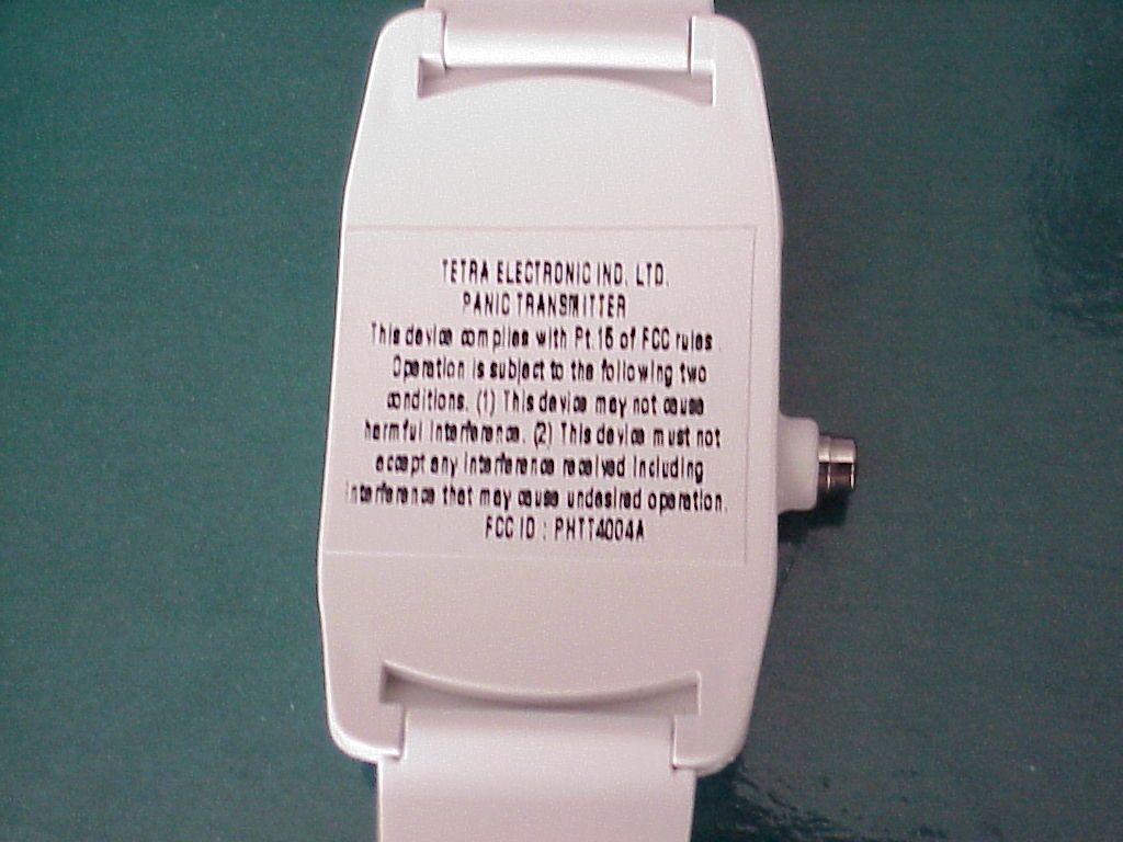
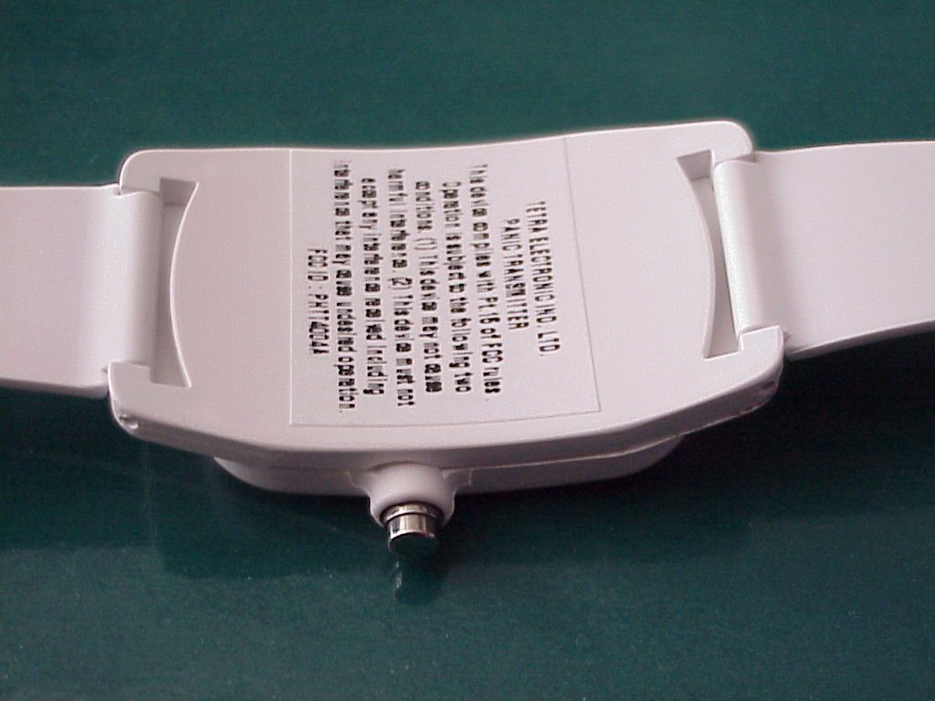
__________________________________________________________________________________________________ (1994) " " 5 58117 : 03-5562775 :03-5561944 5 HASADAN ST. HOLON 58117 ISRAEL, PHONE: 972-3--5562775, FAX: 972-3-5561944 ELECTRONIC IND. LTD. T4004A transmitter. External photograph
ID Label/Location Info
LABEL FOR TETRA’S T4004A TRANSMITTER This device complies with part 15 of FCC rules. Operatio n is s ubje ct to the fo llo wing two co nd itio ns. (1) This device may not cause harmful interference. (2) This device must accept any interference received including interference that may cause undesired operation. 35 mm 22 mm FCC ID : XXXT4004A ELECTRONIC IND. LTD PANI C TRANSM ITTER
ID Label/Location Info
LABEL FOR TETRA’S T4004A TRANSMITTER This device complies with part 15 of FCC rules. Operatio n is s ubje ct to the fo llo wing two co nd itio ns. (1) This device may not cause harmful interference. (2) This device must accept any interference received including interference that may cause undesired operation. 35 mm 22 mm FCC ID : XXXT4004A ELECTRONIC IND. LTD PANI C TRANSM ITTER
ID Label/Location Info
LABEL FOR TETRA’S T4004A TRANSMITTER This device complies with part 15 of FCC rules. Operatio n is s ubje ct to the fo llo wing two co nd itio ns. (1) This device may not cause harmful interference. (2) This device must accept any interference received including interference that may cause undesired operation. 35 mm 22 mm FCC ID : XXXT4004A ELECTRONIC IND. LTD PANI C TRANSM ITTER
ID Label/Location Info
LABEL FOR TETRA’S T4004A TRANSMITTER This device complies with part 15 of FCC rules. Operatio n is s ubje ct to the fo llo wing two co nd itio ns. (1) This device may not cause harmful interference. (2) This device must accept any interference received including interference that may cause undesired operation. 31 mm 23 mm FCC ID : PHTT4004A TETRA ELECTRONIC IND. LTD PANI C TRANSM ITTER
Internal Photos
__________________________________________________________________________________________________ (1994) " " 5 58117 : 03-5562775 :03-5561944 5 HASADAN ST. HOLON 58117 ISRAEL, PHONE: 972-3--5562775, FAX: 972-3-5561944 ELECTRONIC IND. LTD. T4004A transmitter. Internal photographs Photo #1. Main board printed side __________________________________________________________________________________________________ (1994) " " 5 58117 : 03-5562775 :03-5561944 5 HASADAN ST. HOLON 58117 ISRAEL, PHONE: 972-3--5562775, FAX: 972-3-5561944 ELECTRONIC IND. LTD. Photo #2. Main board component side
Operational Description
__________________________________________________________________________________________________ (1994) " " 5 58117 : 03-5562775 :03-5561944 5 HASADAN ST. HOLON 58117 ISRAEL, PHONE: 972-3--5562775, FAX: 972-3-5561944 ELECTRONIC IND. LTD. Date: 28 th January 2001 Attestation Statement ItemT4004A transmitter Frequency433.92 MHz ModulationASK FunctionEmergency transmissions. Activates the TE4000 Emergency system to call the central station and get medical and other emergency services. Signal durationEmergency signal: 4.5 seconds max. Supervision signal: 4.5 seconds max. Manual operationUpon activation of the push button, the transmitter transmits the emergency signal. Supervisor transmissionsThe transmitter transmits automatically a supervision signal to the receiver every 6 to 7.5 hours. We declare that the above information is correct and describes accurately the operation of the T4004A transmitter. Gyora Reppen Tetra Elec. Ind.
Operational Description
__________________________________________________________________________________________________ (1994) " " 5 58117 : 03-5562775 :03-5561944 5 HASADAN ST. HOLON 58117 ISRAEL, PHONE: 972-3--5562775, FAX: 972-3-5561944 ELECTRONIC IND. LTD. Date: 28 th January 2001 Attestation Statement ItemT4004A transmitter Frequency433.92 MHz ModulationASK FunctionEmergency transmissions. Activates the TE4000 Emergency system to call the central station and get medical and other emergency services. Signal durationEmergency signal: 4.5 seconds max. Supervision signal: 950 msec max. Manual operationUpon activation of the push button, the transmitter transmits the emergency signal. Supervisor transmissionsThe transmitter transmits automatically a supervision signal to the receiver every 75 min (one hour and 15 min). We declare that the above information is correct and describes accurately the operation of the T4004A transmitter. Gyora Reppen Tetra Elec. Ind.
Schematics
C368p J2 1 J1 1 01.00.00.01 3 TR-1-v 2 A 11 Thursday , December 21, 2000 TitleSize Document Number Rev Date: Sheet of C101.5p 433,92MHz C41n J3 1 S17914S R74.7k C118.2p R44.7k R210 C173.3p C5100n L2 22nH C6100n C11n R31.5M BAT C15 10p ANT PCB C122.2p L1 47nH Q1 BC 847C U1PI C12C 508_SO 1 23 4 567 8 VD D GP5/OSC1/CLKIN GP4/OSC2 GP3/ MC LR /Vpp GP2/TOCKI GP1GP0 Vs s Q2 BFR 92 3,2V RZ1 RO2101A 13 42 INOUT G1G R110k C8150p R9100 C71n
Test Report
Test Report No.8012307599 On TETRA Electronics Ind. Ltd. Emergency Tag Model: T-4004A From The Standards Institution Of Israel Industry Division Telematics Laboratory EMC Section Test Report No.:8012307599Page 1 of 2 Pages Title: Test on Emergency TagModel: T-4004A Order placed by: TETRA Electronics Ind. Ltd. Address: 5 Hasadan str., Industrial zo ne. Holo n 58117. Israel Sample for test selected by: The orderer T he date of test: 04/01/2001. Description of Equipment Under T est (EUT ): Emergency Tag Model: T-4004A Manufactured by: TETRA Electronics Ind. Ltd. Reference documents: ! CFR 47 FCC Rules and Regulations: Part 15. Radio frequency devices. Subpart B: Unintentional radiators Sec.15.109 Subpart C: Intentio nal radiators. Sec. 15.231 This Test Report contains 23 pages and may be used only in full. This Test Report applies only to the specimen tested and may not be applied to other specimens of the same product. Test Report No.:8012307599Page 2 of 2 Pages Title: Test on Emergency TagModel: T-4004A Table of Contents 1.EUT DESCRIPTION AND OPERATION3 1.1.G EN ERA L D ESCRIP TIO N :3 1.2.EUT’ S G EN ERA L V IEW :5 1.3.EUT’ S I NTERNAL V IEW :6 1.4.EUT' S SUB - ASSEMBLI ES LIS T :8 1.5.EUT S ETUP AND OP ERATION :8 2.TEST SPECIFICATION, METHODS AND PROCEDURES9 3.ADDITIONAL DEVIATIONS OR EXCLUSIONS FROM THE TEST SPECIFICATIONS9 4.MEASUREMENTS, EXAMINATIONS AND DERIVED RESULTS10 4.1.L OCATION OF THE T EST S ITE :10 4.2.T ES T CO N DITIO N :10 4.3.E MISSION TESTS :10 4.4.I NITIAL VISUAL CHECK AND FUNCTIONAL TEST :10 4.5.R ADIATED EMISSION TEST : 11 5.COMPLIANCE WITH SPECIFICATION16 6.APPENDIX 1: TEST EQUIPMENT USED17 7.APPENDIX 2: ANTENNA FACTOR AND CABLE LOSS18 8.APPENDIX 3: TEST CONFIGURATION ILLUSTRATION20 Test Report No.:8012307599Page 3 of 2 Pages Title: Test on Emergency TagModel: T-4004A 1. EUT Description and operation 1.1. General description: Description of Equipment Under T est (EUT ): Emergency Tag Model: T-4004A Manufactured by: TETRA Electronics Ind. Ltd. The EUT is an Emergency Tag, attached to the human body and interacting with a base telephone unit. The EUT contains a low power transmitter. The EUT’s basic parameters are : Fundamental frequency - 433.92 MHz. Type of modulation used:ASK Rated RF po wer 0.001 WT The EUT's dimensio ns are: 5 x 2.4 x 0.8 cm appro x. The EUT's power co nsumption from two 3.0 VDC battery : 0.015A The EUT's block diagram is sho wn in Figure 1. Test Report No.:8012307599Page 4 of 2 Pages Title: Test on Emergency TagModel: T-4004A Figure 1 :EUT's block diagram Resonator 433.92 MHz Matching Circuit Controller Antenna Switch Test Report No.:8012307599Page 5 of 2 Pages Title: Test on Emergency TagModel: T-4004A 1.2. EUT’s General View: Test Report No.:8012307599Page 6 of 2 Pages Title: Test on Emergency TagModel: T-4004A 1.3. EUT’s Internal View: Main board. Printed side Test Report No.:8012307599Page 7 of 2 Pages Title: Test on Emergency TagModel: T-4004A Main board. Component side Test Report No.:8012307599Page 8 of 2 Pages Title: Test on Emergency TagModel: T-4004A 1.4. EUT's sub-assemblies list: EUT’s sub-assemblies list is detailed in table 1. Table 1- Sub-assemblies list FunctionMarking/Serial No./ Model Main boardTetra P/N 84T8521S01 Batteries2X Model 386 1.5. EUT setup and operation: The EUT was operated in operation modes as detailed in table 2. Table 2 - Modes of operations No.Mode of operationEmissions Measurements 1Normal operatio n –Standbyper FCC Part 15 Subpart B 2Normal operatio n Transmissio nper FCC Part 15 Subpart C Test Report No.:8012307599Page 9 of 2 Pages Title: Test on Emergency TagModel: T-4004A 2. Test specification, Methods and Procedures Test Specification : ! CFR 47 FCC Rules and Regulations: Part 15. Radio frequency devices. Subpart B: Unintentional radiators. Sec.15.109 Subpart C: Intentio nal radiators. Sec. 15.231 Methods and Procedures : ! ANSI C63/4/1992: "American National Standard for Methods of Measurement of Radio- Noise Emissions from Low-Voltage Electrical and Electronic Equipment in the range of 9 kHz to 40 GHz. 3. Additional deviations or exclusions from the test specifications Not applicable. Test Report No.:8012307599Page 10 of 2 Pages Title: Test on Emergency TagModel: T-4004A 4. Measurements, examinations and derived results 4.1. Location of the Test Site: Radiated emission tests were co nducted in an Open Area Test Site located at Kibbutz Native Halamed Hai in Emek HaEla, Israel. 4.2. Test condition: Temperature: 22 °C Humidity:60 % 4.3. Emission tests: "The initial scans were made using a peak detector but still using the appropriate CISPR (Quasi-Peak) detector IF bandwidth. "The tolerance limit was set 6 dB below the specification limit. Levels above the tolerance limit were retested using the Quasi-Peak detector or an average detector. "The tolerance limit was set 10 dB below the specification limit. Levels above the tolerance limit were retested using the Quasi-Peak detector. "If the result with a Quasi-Peak detector exceeds the specification limit, it is marked with “Fails” in the margin, if it is within the limits of uncertainty for the measurement, it is marked with a “*”. 4.4. Initial visual check and functional test : Initial visual check and brief built- in- test (BIT) of the EUT was performed before testing.- No external damages were found. - The BIT test o n the EUT passed successf ully. Test Report No.:8012307599Page 11 of 2 Pages Title: Test on Emergency TagModel: T-4004A 4.5. Radiated emission test: 4.5.1. Preliminary radiated emission tests: Preliminary radiated measurements were performed in a shielded chamber at a distance of 3 meters. Operatio n modes: transmission, standby. For each mode of operation the frequency spectrum was monitored. 4.5.2. Final measurements: The EUT was arranged on a turntable at the Open Area Test Site. The test layout is presented in Appendix 2. All measurements at the Open Area Test Site were performed at a 10 m measurement distance. The antennas used for this…
Text truncated - open the document above for the full version.
Test Setup Photos
__________________________________________________________________________________________________ (1994) " " 5 58117 : 03-5562775 :03-5561944 5 HASADAN ST. HOLON 58117 ISRAEL, PHONE: 972-3--5562775, FAX: 972-3-5561944 ELECTRONIC IND. LTD. T4004A transmitter. Test setup photographs Photo#1. Radiated emissions measurements on the open site __________________________________________________________________________________________________ (1994) " " 5 58117 : 03-5562775 :03-5561944 5 HASADAN ST. HOLON 58117 ISRAEL, PHONE: 972-3--5562775, FAX: 972-3-5561944 ELECTRONIC IND. LTD. Photo#2. Radiated emissions measurements on the open site __________________________________________________________________________________________________ (1994) " " 5 58117 : 03-5562775 :03-5561944 5 HASADAN ST. HOLON 58117 ISRAEL, PHONE: 972-3--5562775, FAX: 972-3-5561944 ELECTRONIC IND. LTD. Photo#3 Radiated emissions measurements on the open site __________________________________________________________________________________________________ (1994) " " 5 58117 : 03-5562775 :03-5561944 5 HASADAN ST. HOLON 58117 ISRAEL, PHONE: 972-3--5562775, FAX: 972-3-5561944 ELECTRONIC IND. LTD. Photo#4. Radiated emissions measurements on the open site
Contact Information
Applicant
Gyora Reppen(R&D Manager)
Technical Contact
Tetra Electronic Ind. Ltd.Gyora Reppen
[email protected]+972-3-5562775
5, Hasadan Str., Industrial Zone · Holon · Israel
Non-Technical Contact
Tetra Electronic Ind. Ltd.Araham Duvnikov
[email protected]+972-3-5562775
Test Firm
The Standards Institution of IsraelYuri Rozenberg
Technical Specifications
| # | Rule Parts | Frequency Range | Power Output |
|---|---|---|---|
| 1 | 15C | 433.92 MHz - 433.92 MHz | - |