PI2MEICTR24A1RF Color Camera
Marshall Electronics Inc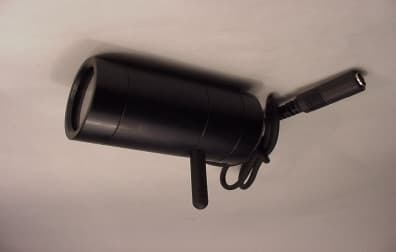
Click to zoom
Application Details
- Equipment Class
- DXX - Part 15 Low Power Communication Device Transmitter
- Date of Grant
- Apr 05, 2001
- Application Purpose
- Original Equipment
- Date of Application
- Mar 08, 2001
- Equipment Note
- RF Color Camera
- Frequency Range
- 2411.60000000 - 2471.60000000
- Company
- Marshall Electronics Inc
- Country
- United States
Documents & Files
Document Text
Text extracted from the exhibit documents filed with the FCC. Open a document above to read the original.
Users Manual
USER’S OPERATION MANUAL 2.4GHz RF (Tx) Color Camera Item No. : V-2297RF 1. PRODUCT DESCRIPTION The RF color camera unit consists of a color CMOS camera and a transmitter in a durable metal casing, and transmit a video signal by radio ; replacing complicated cabling. Features : ! !! ! 1/3” format color camera with a transmitter ! !! ! 2.4GHz carrier frequency, 50mW ! !! ! Auto white balance, auto gain control & auto exposure ! !! ! Durable metal casing ! !! ! Compact size ! !! ! Low power consumption, 55mA 2. SAFETY ! !! ! When installing the unit, take care that the power cord does not become trapped or damaged by sharp edges. ! !! ! Before connecting a power source to the unit, make sure that a supplied voltage is correct. ! !! ! Disconnect the power cord when the unit is to be out of use for lengthy periods. ! !! ! Never replace a damaged power cable personally. ! !! ! Never bend or give a pressure to an antenna of the unit from any directions. 3. INSTALLATION AND OPERATION (1) Make sure setting 2.4GHz video RF receiver and color monitor units properly. (2) Turn RF receiver and monitoring units on, and select a frequency channel on a RF receiver. (3) Connect power plug of the unit to a proper power supply source. (input voltage : 7.5 – 12vdc) (4) Open a rear cap of the RF camera unit. (5) Make a fine adjustment of a Tx radio frequency, to a Rx channel selected, by carefully rotating a VR located at right top side of the transmitter board with a non-metallic adjustment driver while observing a picture quality on a monitor for a stable and best reproduction. Caution - Be careful not to exceed adjustment range of the VR. If not, it can result a damage on the VR. - Be careful not to touch any other parts of the board except the VR with a adjustment tool. (6) Close a rear cap back. (7) Place and mount the camera unit properly at a location with a desired view. 4. CARE AND MAINTENANCE The unit is maintenance-free, therefore never open it except for frequency and focus setting adjustments. The unit should be cleaned externally only with a soft, dry cloth or brush. 5. TECHNICAL DATA Operating voltage : 7.5 – 12vdc Current consumption : approx. 55mA Imager : 1/3” color CMOS sensor Number of pixels : 510 X 492 Gamma correction : 0.45 Transmitter frequency : 2.411GHz – 2.473GHz Modulation : FM Output power : 10dBm Cha nnel ba ndw idth : 8MH z Phase noise @10k : - 86dBc/Hz Frequency stability : -0.1% or better Line of sight : 300 feet (strongly dependent on surrounding conditions) Di mensio n : ∅31 X 66 mm (witho ut a ntenna) [The specifications are subject to change without a notice.] 6. FAULT RECTIFICATION No picture : RF camera, receiver or monitor not correctly connected or not supplied with power The distance between RF camera and receiver is too great. A frequency of the camera has been adjusted differently from the receiver channel selected. Noisy picture : The distance between camera and receiver is too great. A frequency of the camera has been adjusted differently from the receiver channel selected. Metallic barriers exist at between camera and receiver. The RF camera and/or receiver antennas are placed or oriented disadvantageously. A strong source of interference exists at nearby. Supply voltage of a power source is too small. View from the back after opening a rear cap VR for frequency setting Front cap Antenna Appearance of a camera (side view) Rear cap MARSHALL ELECTRONICS, INC. 1910, East Maple Ave., El Segundo, CA 90245, U.S.A. Tel : 1-310-333-0606, 1-800-800-6608 Fax : 1-310-333-0688 URL : http://www.mars-cam.com FCC ID : PI2 MEICTR24A1 This device complies with part 15 of the FCC Rules. Operation is subject to the followings two conditions; (1) This device ma y no t cause har mful interference, a nd (2) this device must accept any interference received, including interference that may cause undesired operation. Cauti of thi party autho
Block Diagram
MARSHALL ELECTRONICS, INC. 1910, EAST MAPLE AVENEUE, EL SEGUNDO, CA 90245, U.S.A. TEL : 1-310-333-0606, 1-800-800-6608 FAX : 1-310-333-0688 URL : http://www.mars- cam.com SUBJECT : BLOCK DIAGRAM OF V-2297RF Date : 22 Feb, 2001 CAMERA SECTION RF TRANSMITTER SECTION + 5V + 5V RF OUTPUT VIDEO SIGNAL LENS CMOS IMAGE SENSOR VIDEO INPUT CIRCUIT RF MODULATO R RF AMP
External Photos
(External Photos)
ID Label/Location Info
MARSHALL ELECTRONICS, INC. 1910, EAST MAPLE AVENEUE, EL SEGUNDO, CA 90245, U.S.A. TEL : 1-310-333-0606, 1-800-800-6608 FAX : 1-310-333-0688 URL : http://www.mars- cam.com SUBJECT : LABELLING LOCATION AND CONTENTS OF V-2297RF Date : 22 Feb, 2001 1. FCC LABELLING LOCATION LABELLING LOCATION 2. CONTENTS FCC ID : PI2MEICTR24A1 FCC ID :
ID Label/Location Info
MARSHALL ELECTRONICS, INC . 1910 EAST MAPLE AVENUE, EL SEG UNDO, CA 90245, USA TEL: 1-310-333-0606, 1-800-800-6608 FAX: 1-310-333-0688 URL: http//www.mars-cam.com DATE:23 MARCH 2001 SUBJECT: REVISED IDENTIFICATION LABEL FCC ID: PI2MEICTR24A1 731 CONFIRMATION NUMBER EA100282 Correspondence Reference number: 18528 We hereby request that below be shown as identification label with regards the above listed application. LINE 28A to show: FCC ID: PI2MEICTR24A1 LINE 28B to show: FCC ID: PI2MEICTR24A1 Nathan Modukhay MARSHALL ELECTRONICS, INC.
Internal Photos
(Internal Photos)
Operational Description
MARSHALL ELECTRONICS, INC. 1910, EAST MAPLE AVENEUE, EL SEGUNDO, CA 90245, U.S.A. TEL : 1-310-333-0606, 1-800-800-6608 FAX : 1-310-333-0688 URL : http://www.mars- cam.com SUBJECT : RF DESCRIPTION OF V-2297RF Date : 22 Feb, 2001 1.BLOCK DIAGRAM ANTENNA VIDEO IN POWER IN RF OUT 2. DESCRIPTION OF RF SIGNAL PROCESSING A video signal is mixed with a DC base level signal in a video input circuitry. This signal is delivered to a VCO (Voltage Control Oscillator), and it is modulating a RF output signal from the VCO. After VCO modulated, the RF signal goes to a Power Amplifier, which bursting a modulated signal, and then goes to an antenna to be transmitted. By changing a DC base signal using a built-in potentiometer, a carrying frequency can be adjusted. VIDEO INPUT CIRCUIT RF MODULATOR RF AMP
Schematics
TITLE PART# DATE DWG# MARSHALL ELECTRONICS, INC. cylindric RF(Tx)camera -1 : <Schematic> 5 Feb, 2001 V-2297RF YSD-010203 IC1 OV7910E 1 2 3 4 5 6 7 8 9 10 11 12 13 14 15 16 17 18 19 20 21 22 23 24 25 26 27 28 29 30 31 32 33 34 35 36 37 38 39 40 41 42 43 44 45 46 47 48 FSO FSIN 10K R15 R14 10K R13 10K R3 10K C17 220n DVDD C9 0.1mkF AVDD C1 0.1mkF C2 0.1mkF C3 0.1mkF C4 0.1mkF C11 0.1mkF R2 2.37K R1 8.06K C10 0.1mkF AVDD R4 100 R7 10K R8 10K AVDD DVDD R23 10K R24 10K C5 0.1mkF R18 10K R17 10K R16 10K 1 2 3 4 OUT POWER GND VIDEO C8 0.1mkF R6 10K CLKIN DVDD R5 1M R20 10K R18 10K R21 10K R22 10K Q1 14.31818MHz C6 33pF C7 33pF VIDEO CMOS COLOR CAMERA SECTION VIDEO TRANSMITTER SECTION POWER U1 78L05ACZ VI VD GND 1 2 3 DVDD AVDD R9 10 R10 10 R11 10 SVDD SVDD C16 4.7mkF C14 4.7mkF C13 4.7mkF C12 0.1mkF C15 22mkF R30 390 ANT IC1 1 2 3 4 RF in RF out ERA5SM C13 33pF VCO1 PVS-2401 C12 33pF R12 27 R13 68 R14 68 R11 27 L1 8.2nH L2 8.2nH L3 8.2nH L4 8.2nH R15 270 R16 270 C10 22pF C5 100nF C6 1000pF C7 100nF C8 22pF VCC RF OUT VT R10 8.7K R4 7.5K R2 5.0K R1 68 C9 47.0mkF R7 75 R5 75 C11 220pF R6 1.0K 2 1 4 3 U1 NJU78L05UA U2 NJU7201U35 5 6 GND GND GND POWER VIDEO IN POWER JP1 C1 4.7mkF C2 1000pF D1 DL4001 1 2 3 1 2 3
Test Report
KTL Korea Testing Laboratory Page 1 of 11 TEST REPORT This test report only responds to the tested sample and shall not be reproduced except in full without written approval of the Korea Testing Laboratory. Tested and reported by Reviewed by Jeong-Min Kim , Senior Engineer Won-Seo Cho , EMC Team Leader KOREA TESTING LABORATORY FG101-01-02-00 222-13, Guro-Dong Guro-Gu Seoul Korea 152-053 http://www.ktl.re.kr Ref. Report No. 01-341-003 Name and address of the applicant Marshall Electronics Inc. 1910, East Maple Ave. Elsegundo, CA 90245, U.S.A Standard / Test regulation FCC Part 15, Subpart C Test result Pass Incoming date : February 6, 2001 Test item(s) ; Low Power Communication Device Transmitter (RF Color Camera) Model/type ref. ; V-2297RF Manufacturer ; Marshall Electronics Inc. Additional information ; -Required Authorization : Certification -FCC ID. : PI2MEICTR24A1 Test date : March 5, 2001 Issue date : March 9, 2001 Ref. Report No. 01-341 - 003 2 Page of 11 TABLE OF CONTENTS I. GENERAL INFORMATION ................................................................................................... 3 1. Grantee’s Name and Mailing Address 2. Manufacturer's Name and Mailing Address 3. Equipment Descriptions 4. Rules and Regulations 5. Measuring Procedure 6. Date of Measurement •±. GENERAL REQUIREMENTS OF THE EUT ..............................................................4 1. Labelling Requirement (Section 15.19) 2. Information to User (Sections 15.21) 3. Special Accessories (Section 15.27) •≤. RADIATED EMISSION MEASUREMENT (Section 15.249) ................................................ 5-9 1. Test Procedure 2. Photograph for the worst case configuration 3. Sample Calculation 4. Measurement Data •≥. FREQUENCY STABILITY............................................................................................10 •¥. TEST EQUIPMENTS USED FOR MEASUREMENT..........................................................11 Ref. Report No. 01 - 341 - 003 3 Page of 11 •∞. GENERAL INFORMATION 1. Grantee’s Name and : Marshall Electronics Inc. Mailing Address 1910, East Maple Ave. Elsegundo, CA 90245, U.S.A 2. Manufacturer's Name and : Marshall Electronics Inc. Mailing Address 1910, East Maple Ave. Elsegundo, CA 90245, U.S.A 3. Equipment Descriptions 3.1 Operating Frequency : 2411.6 MHz ~ 2471.6 MHz 3.2 Type of Emission : Frequency Modulation 3.3 Power Supply : DC 12 V 4. Rules and Regulations : FCC Part 15, Subpart C 5. Measuring Procedure : ANSI C63.4-1992 6. Date of Measurement 6.1 Line Conducted : Not Applicable 6.2 Radiated Emission : March 5, 2001 Ref. Report No. 01 - 341 - 003 4 Page of 11 •±. GENERAL REQUIREMENTS OF THE EUT 1. Labelling Requirement (Section 15.19) This device complies with Part 15 of the FCC Rules. Operation is subject to the following two conditions: (1) this device may not cause harmful interface, and (2) this device must accept any interference received, including interference that may cause undesired operation. 1.1 Location of Label : User’s Guide Manual 1.2 How Applied : Printing 2. Information to User (Section 15.21) The following or similar statements were provided in the manual for user instruction. Please refer page 2 of the attached manual for details. CAUTION : Any changes or modifications in construction of this device which are not expressly approved by the party responsible for compliance could void the user's authority to operate the equipment. 3. Special Accessories (Section 15.27) 3.1 Were the special Accessories provided? [ ] yes, [ x ] no 3.2 If yes, details for the special accessories are as follows : 3.3 If yes, were the appropriate instructions provided on the first page of the text concerned with the device? [ ] yes, [ ] no 3.4 Are these accessories provided of the type which can be readily obtained from multiple retail outlets ? [ ] yes, [ ] no And therefore does the manual specify what additional components or accessories are required to used in order to comply with the Rules? [ ] yes, [ ] no Ref. Report No. 01 - 341 - 003 5 Page of 11 •≤. RADIATED EMISSION MEASUREMENT (Section 15.249) 1. Test Procedure 1.1 Preliminary Testing for Reference This RF Color Camera (EUT) is designed to operate in the band 2411.6 MHz to 2471.6 MHz by changing the DC base signal. According to section 15.31(m), the measurements were performed with three operating frequencies which were selected as bottom, middle, and top frequency in the operating band. Preliminary testing was performed in a KTL absorber-lined room to determine the emission characteristics of the EUT. The EUT was placed on the wooden table which has dimensions of 0.8 meters in height, 1 meter in length and 1.5 meters in width. Receiving antenna (Biconical antenna : 30 to 300 MHz, Log-periodic antenna : 200 to 1000 MHz or Horn Antenna : 1 to 18 GHz) was placed at the distance of 1 meter from the EUT. An attempt was made to maximize the emission level with the various configurations of the EUT while rotating the table and varying antenna height. Emission levels from the EUT with various configurations were examined on a Spectrum Analyzer connected with a RF amplifier and graphed by a plotter. 1.2 Final Radiated Emission Test at an Absorber-Lined Room The final measurement of radiated field strength was carried out in a KTL Absorber-Lined Room that was listed up at FCC according to the "Radiated Emissions Testing" procedure specified by ANSI C63.4. Based on the test results in preliminary test, measurement was made in same test set up and configuration which produced maximum emission level. Receiving antenna was installed at 3-meter distance from the EUT, and was connected to an EMI receiver or spectrum analyzer (for above 1GHz) with a RF amplifier. Turntable was rotated through 360 degrees and receiving antenna height was varied from 1 to 4 meters above the ground plane to read maximum emission level. If necessary, the radiated emission measurements could be performed at a closer distance than specified distance…
Text truncated - open the document above for the full version.
Contact Information
Applicant
David Quinlan(General Manager)
Test Firm
Korea Testing LaboratoryJeong-Min Kim
Technical Specifications
| # | Rule Parts | Frequency Range | Power Output |
|---|---|---|---|
| 1 | 15C | 2.41 GHz - 2.47 GHz | - |