PIKFRS101Family Radio Service
Shenzhen Daxian Digital Telecommunication Limited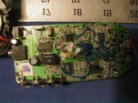
Click to zoom
Application Details
- Equipment Class
- FRF - Part 95 Family Radio Face Held Transmitter
- Date of Grant
- Feb 11, 2002
- Application Purpose
- Original Equipment
- Date of Application
- Feb 11, 2002
- Equipment Note
- Family Radio Service
- Frequency Range
- 462.55000000 - 462.71000000
- Country
- Hong Kong
Documents & Files
Document Text
Text extracted from the exhibit documents filed with the FCC. Open a document above to read the original.
Users Manual
Made in China USER’S MANUAL BEFORE OPERATING THIS PRODUCT KEEP FOR YOUR REFERENCE PLEASE READ THESE INSTRUCTIONS CAREFULLY 14 Channel 2 Way Radios with CTCSS security MODEL: FRS101 MIC M2 M3 S M1 CTCSS B/K VOL CALL BUSY SCAN FRS-101 1 CONTENTS 2 Changing CHANNELS ........................................................................ 9 CTCSS Tone Adjustment.............................................. ...................... 9 Channel Monitoring............................................................................. 9 Channel Monitor Locking .................................................................... 9 Sending Call Tones............................................................................. 9 CHANNEL SCAN ............................................................................... 10 KEY TONE Selection ......................................................................... 10 Backlight Feature .............................................................................. 10 Keylock Feature ................................................................................ 10 Memory Feature ................................................................................ 10 Battery Charge Level/Low Battery Indication ........................................ 11 To Charge the FRS Radio .................................................................... 11 SPECIFICATIONS .................................................................................. 12 FCC NOTICE .......................................................................................... 15 Battery Installation .................................................................... 5 Installing the Belt Clip ................................................................. 6 Removing the Belt Clip ................................................................ 6 Connecting the Adapter .............................................................. 6 Accessory Connection ................................................................ 6 LCD Screen ............................................................................... 7 Turning the Unit ON ................................................................... 8 Turning the Unit OFF .................................................................. 8 Adjusting Speaker Volume .......................................................... 8 Receiving a Signal ..................................................................... 8 Transmitting a Signal .................................................................. 8 OPERATION PRODUCT DESCRIPTION.......................................................... 1 CONTENTS ............................................................................... 2 SPECIAL FEATURES................................................................. 3 SETTING UP YOUR FRS RADIO 43 SPECIAL FEATURES SPECIAL FEATURES BELT CLIP CALL button - Press to transmit CALL Tones. PTT (PUSH TO TALK) button - Press to transmit. SPEAKER S Button - Used to activate/deactivate CHANNEL SCAN. LCD (Liquid Crystal Display) Screen - Displays current channel selection and other radio status symbols. ANTENNA MIC - MICROPHONE MONITOR MON button - Press to tune in and hold onto weak signals. Button - Press to increase or decrease the volume level. Button - Used to activate the CTCSS tone adjustment mode Button -Used to turn on or off the backlight. Button - Press to store and re-call memory setting EAR/MIC/CHARGER JACK - When the earphone is connected into this jack the voice of the speaker will shift to the earphone. POWER button - Press and hold the POWER button to turn your unit ON/OFF. UP /DOWN buttons - Press to change channels VOL CTCSS B/K M1 M2 M3 BATTERY COMPARTMENT- Houses three(3) “AAA” alkaline or Ni-MH rechargeable batteries The FRS101 is a lightweight, compact two-way communication device that can be used to communicate with family or friends at parks, shopping malls, sporting events, concerts-any indoor or outdoor activity! NOTE: The maximum transmission range will vary depending on terrain and environment. Range will be greater in open fields, while range is shorter WAY RADIO. Please read this User’s Manual carefully to get the most out of your TWO- Included in Your Package When you unpack your FRS radio, you should find the following items enclosed in the package: • 1 14-channel FRS unit • 1 Belt Clip • This manual SAVE CIRCUITRY. This unit may not ensure privacy of communication. Other features include ELECTRONIC VOLUME CONTROL and BATTERY The FRS101 has 14-CHANNELS, featuring a multi-functional LCD Screen (which displays the current channel and various status icons). 467.7125MHz). The FRS101 is compatible with other brands utilizing the same frequency band (operating in the frequency range from 462.5625MHz to The FRS101 Radio is the newest generation in personal two-way communications. The FRS101 Radio operates in a license-free radio band (no FCC license is needed for its operation), on any of the 14 license- free channels. PRODUCT DESCRIPTION within and around buildings or large structures. MON PTT CALL MIC M2 M3 S M1 CTCSS B/K VOL CALL BUSY SCAN FRS-101 ANTENNA POWER ON/OFF BUTTON CALL BUTTON PTT BUTTON MONITOR BUTTON BELT CLIP UP BUTTON DOWN BUTTON LCD SCREEN SCAN BUTTON MEMORY BUTTONS SPEAKER CTCSS BUTTON BACKLIGHT/KEYLOCK BUTTON MICROPHONE BATTERY COMPARTMENT (located inside) VOLUME CONTROL 8 6 7 5 Setting Up Your FRS Radio Setting Up Your FRS Radio OPERATION Setting Up Your FRS Radio Installing the BELT CLIP Removing the BELT CLIP Connecting the ADAPTER Accessory Connection 1. Slide the belt clip into the belt clip slot as shown in figure 3. 2. Ensure you hear a click to indicate that it is securely in place. 1. Pull the belt clip tab away from the unit, as shown in figure 4. 2. While pulling the belt clip latch, push down the belt clip to To charge the unit using “AAA” Ni-MH rechargeable batteries, insert the round connector of th…
Text truncated - open the document above for the full version.
External Photos
EUT External Photographs EUT - Top View EUT - Bottom View
ID Label/Location Info
FCC ID Labeling and Location Proposed FCC ID Labeling Proposed FCC ID Location Bottom Side of EUT 5.3 FCC Warning Statement Per FCC Section 15.19 (3) and 15.19 (5), all devices shall bear the following statement in a conspicuous location on the device: “ This device complies with Part 15 of the FCC Rules. Operation is subject to the following town conditions: (1) this device may not cause harmful interference, and (2) this device must accept any interference received, including interference that may cause undesired operation.” When the device is so small or for such use that it is not practicable to place the statement specified on it, the information required shall be placed in a prominent location in the instruction manual or pamphlet supplied to the user or, alternatively, shall be placed on the container in which the device is marketed. However, the FCC identifier or the unique identifier, as appropriate, must be displayed on the device. Generally, the FCC Warning Statement is provided with the product manual. A sample of the statement normally is presented in Appendix B of this report as reference. FCC ID: PIKFRS101 Proposed FCC ID Li
Internal Photos
EUT Internal Photographs EUT - Component View EUT - Solder View
Operational Description
Dec 27, 2001 SHENZHEN DAXIAN DIGITAL TELECOMMUNICATIONS LTD. Page ofModel: FRS101 (DX-6221US) Reasearch and Development Department TECHNICAL DOCUMENTS FOR FCC Model : FRS101 462- 467 MHz Band 14 Channels FRS (Family Radio Service) with CTCSS 1 16 Dec 27, 2001 SHENZHEN DAXIAN DIGITAL TELECOMMUNICATIONS LTD. Page ofModel: FRS101 (DX-6221US) Reasearch and Development Department CONTENTS 1. CIRCUIT DESCRIPTION A. Receiver. . . . . . . . . . . . . . . . . . . . . . . . . . . . . . . . . . . . . . .3 B. Transmitter. . . . . . . . . . . . . . . . . . . . . . . . . . . . . . . . . . . . . . . 4-5 2. ALIGNMENT PROCEDURE & SPECIFICATION A. Transmitter. . . . . . . . . . . . . . . . . . . . . . . . . . . . . . . . . . . . . . .6 B. Receiver. . . . . . . . . . . . . . . . . . . . . . . . . . . . . . . . . . . . . . .7 3. FREQUENCY CHART. . . . . . . . . . . . . . . . . . . . . . . . . . . . . . . . . . . . . . .8 2 16 Dec 27, 2001 SHENZHEN DAXIAN DIGITAL TELECOMMUNICATIONS LTD. Page ofModel: FRS101 (DX-6221US) Reasearch and Development Department 3 16 CIRCUIT DESCRIPTION Circuit Composition and Operation Theory The basic explanation for the circuit composition of FRS101 consist mainly of the one board controlling the analog circuit parts and the digital circuit parts for the other control. RECEIVER FRS101 transmission parts is composed in the double conversion system, which has the 1st IF frequency of double 21.7 MHz and the 2nd IF frequency of 450 MHz. With the RF front-end which has an excellent band characteristics and skirt characteristics, the 2 pole MCF used in the 1st IF, and the 3 pole ceramic filter in the 2nd IF, the reception interrupting factors such as the image and the sensitivity repression are reduced for the more stable reception. RF Front-end The signal received by the antenna will be transmitted to the band pass filter through the antenna switching circuit consisted of CT20, LT4, LT7. The front RF amplifier transistor QR1 consists of the LR5, LR6, CR71, CR72, CR81 input band pass filter and LR2, LR3, CR2, CR7, CR16 output band pass filter, primarily diminishes the other signal rather than the 1st IF image and other signal within the reception band and amplifies only the necessary signal within the RF. 1st Mixer The receiver which has been amplifier in the RF frontend is provided to thebase of the 1st mixer QR2. The 1st L/O signal provide from the VCO is supplied to the emitter of Q2 and converted to the 1st IF21.7 MHz. 1st IF Filter and 1st IF Amplifier The signal recovered by QR2 to 21.7 MHz, the 1st frequency, change its impedance through C43, L6 and then is infused to the fundamental MCF which has the center frequency of 21.7 MHz and the width of +/-3.75 KHz. Here, the signal reduces the image and other unwanted signal for the 2nd IF, and changes its impedance again through the RR11. Then signal is infused to QR3, the 1st IF Amplifier. The signal infused to the QR3 is amplified approximately by 20dB in order to acquire the required reception sensitivity, and infused to the IC1 which functions as the 2nd mixer, the 2nd IF amplifier, and the FM detector. 2nd Mixer, and IF, FM Detector (IC101) The received IF signal of 21.7 MHz, which has been infused to IC1 is mixed with the 2nd L/O converted to 450KHz, the 2nd IF frequency. The receiver signal converted to the 2nd IF signal frequency passed through the CF2, the ceramic filter of 450 KHz again. After the limiting inside the IC1 and the FM demodulating by the quadrature detector inside the IC1, the signal offers the output through the 9th oin of IC1. The squelch circuit is composed to detect the noises from the received signal demodulated in the 9th pin of the IC1. For this purpose, the noise filter is using the OP amplifier inside the IC1. Dec 27, 2001 SHENZHEN DAXIAN DIGITAL TELECOMMUNICATIONS LTD. Page ofModel: FRS101 (DX-6221US) Reasearch and Development Department 4 16 Audio Power Amplifier (IC102) The received audio signal, which has been filtered by U4, U5 and adjusted to the appropriate volume by MCU, QR5, QR6, QR7 supplied to the 4th pin of the U6 and amplified approximately by 20dB. Then, it turns up the speaker with the maximum output of 1000mV. The 1st pin of U6 is the speaker power control. If a voltage supply to the 1st pin of U6 is supplied to this terminal, the U6 stops functioning as the audio power amplifier regardless of the signal supplied to the 4th pin of U6, and there is no sound can hear from the spaker. TRANSMITTER Pre-emphasis(U5) The voice signal input from the microphone is pre-emphasized at the U5C. The signal which comes out of the U5A is limited to a certain amplitude for the voice signal not to exceed the allowable bandwidth assigned for transmission. TXPower(QT3) The transmitted signal of approximately 7mW, combined at the driver TR is supplied to the base of QT3 amplifier. The transmitted signal amplifier to 0.4 W here passes the TX LPF of the 2nd characteristics of the LT4and LT5, and RX/TX switching takes place by DT2. After this, the signal is provided to the antenna through thr TX LPF of the 1st characteristics consisted of the LT10. "FRS' FREQUENCY SYNTHEIZER Voltage Control Oscillator (VCO) The VCO oscillates 462.5625 MHz to 467.7125 MHz under the transmission condition and 440.8625 MHz to 446.3125 MHz under the reception condition. The RX/TX VCO consist of the oscillator of the QT13, LT13, DT10, DT11 and QS12. VCO should oscillate relatively low frequency during reception compared to transmission, the DT10 is biased by the QS12. Therefore as a result, the C232 is added in parallel to the resonance circuit of the VCO to oscillate a low frequency. During transmission, a relatively high frequency should oscillate compared to reception. Therefore, the DT is adversely biased by the QT10, and as aresult, the C232 which is added unparalled to the circuit of the VCO is removed to oscillate the desired transmission frequency. The VCO is controlled by the IC4 PLL IC in order to oscillate accurate fre…
Text truncated - open the document above for the full version.
Test Report
Note: This test report is specially limited to the above client company and product model. It may not be duplicated without prior written consent of Bay Area Compliance Laboratory Corporation. This report must not be used by the client to claim product endorsement by NVLAP or any agency of the U.S. Government. FCC PART 95 EMI MEASUREMENT AND TEST REPORT For Shenzhen Daxian Digital Telecommunication Limited No. 2 Industrial Area, Tanxiayong, Songgang, Shenzhen, Guangdong, China FCC ID: PIKFRS101 February 5, 2002 This Report Concerns: Original Report Equipment Type: Family Radio Service (FRS) Test Engineer: Jeff Lee Test Date: January 22, 2002 Reviewed By: John Y. Chan – Engineering Manager Prepared By: Bay Area Compliance Laboratory Corporation 230 Commercial Street Sunnyvale, CA 94085 Tel: (408) 732-9162 Fax: (408) 732 9164 Shenzhen Daxian Digital Telecommunication Ltd. FCC ID: PIKFRS101 Report # R0201144 FCC Part 95 Test Report Page 2 of 24 TABLE OF CONTENTS 1 - GENERAL INFORMATION..................................................................................................................................4 1.1 PRODUCT DESCRIPTION FOR EQUIPMENT UNDER TEST (EUT) ..............................................................................4 1.2 OBJECTIVE.............................................................................................................................................................4 1.3 TEST METHODOLOGY............................................................................................................................................4 1.4 TEST FACILITY.......................................................................................................................................................4 1.5 TEST EQUIPMENT LIST...........................................................................................................................................5 2 - SYSTEM TEST CONFIGURATION.....................................................................................................................6 2.1 JUSTIFICATION.......................................................................................................................................................6 2.2 EUT EXERCISE SOFTWARE....................................................................................................................................6 2.3 SPECIAL ACCESSORIES...........................................................................................................................................6 2.4 SCHEMATICS / BLOCK DIAGRAM...........................................................................................................................6 2.5 EQUIPMENT MODIFICATIONS.................................................................................................................................6 2.6 CONFIGURATION OF TEST SYSTEM.........................................................................................................................7 2.7 TEST SETUP BLOCK DIAGRAM...............................................................................................................................7 3 - REQUIREMENTS OF PROVISIONS ...................................................................................................................8 3.1 GENERAL PROVISIONS...........................................................................................................................................8 3.2 REQUIREMENTS AND TEST SUMMARY...................................................................................................................8 3.3 LABELING REQUIREMENT......................................................................................................................................8 4 - EFFECTIVE RADIATED POWER.......................................................................................................................9 4.1 PROVISION APPLICABLE.........................................................................................................................................9 4.2 TEST PROCEDURE..................................................................................................................................................9 4.3 TEST EQUIPMENT.................................................................................................................................................10 4.4 TEST RESULTS.....................................................................................................................................................10 5 - MODULATION CHARACTERISTICS ..............................................................................................................11 5.1 PROVISION APPLICABLE.......................................................................................................................................11 5.2 TEST PROCEDURE................................................................................................................................................11 5.3 TEST EQUIPMENT.................................................................................................................................................11 5.4 TEST RESULTS.....................................................................................................................................................11 6 - OCCUPIED BANDWIDTH OF EMISSION.......................................................................................................14 6.1 PROVISION APPLICABLE.......................................................................................................................................14 6.2 TEST PROCEDURE................................................................................................................................................14 6.3 TEST EQUIPMENT...............................................................................…
Text truncated - open the document above for the full version.
Test Setup Photos
Test Setup Photographs Radiated Emission Setup - Front View Radiated Emission Setup - Rear View
Contact Information
Applicant
Raymond Ng(Senior Marketing Manager)
Test Firm
Bay Area Compliance LaboratoryJohn Chan
Technical Specifications
| # | Rule Parts | Frequency Range | Power Output | Emission | Tolerance |
|---|---|---|---|---|---|
| 1 | 95B | 462.55 MHz - 462.71 MHz | 316.00 mW | 11K0F3E | 2.3000000000 ppm |
Other Applications from Shenzhen Daxian Digital Telecommunication Limited
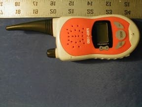
PIKFRS100
Feb 20, 2002Family Radio Service
Equipment Class
FRF - Part 95 Family Radio Face Held Transmitter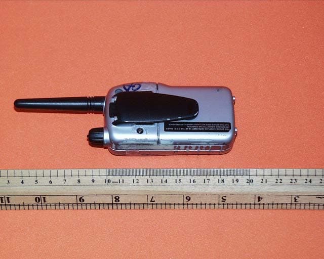
PIKMAX400
Mar 22, 2001Family Radio Service
Equipment Class
FRF - Part 95 Family Radio Face Held Transmitter