PIM797BColor Monitor
NESO Technology Inc.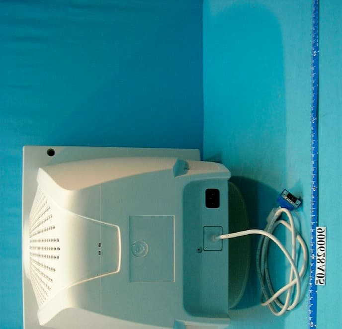
Click to zoom
Application Details
- Equipment Class
- JBP - Part 15 Class B Computing Device Peripheral
- Date of Grant
- Jul 23, 2001
- Application Purpose
- Original Equipment
- Date of Application
- Jul 23, 2001
- Equipment Note
- Color Monitor
- Company
- NESO Technology Inc.
- Country
- Taiwan
Documents & Files
Document Text
Text extracted from the exhibit documents filed with the FCC. Open a document above to read the original.
Users Manual
1 Pomona FD 797P 17” “Trinitron ® ” Color Monitor User Manual 4/2001 IBM PC, IBM PS/2, and VGA are registered trademarks of International Business Machines Corp. Windows, DOS are registered trademarks of Microsoft Corp. Macintosh is a registered trademark of Apple Computer Inc. ENERGY STAR is a U.S. registered mark. NESO reserve the right to make changes or improvement in this product described in this manual without notice. FD 797P User’s Manual 2 Federal Communications Commission (F.C.C.) Statement This equipment has been tested and found to comply with the limits for a class B digital device, pursuant to Part 15 of the FCC rules. These limits are designed to provide reasonable protection against harmful interference in a residential installation. This equipment generates, uses and can radiate radio frequency energy and, if not installed and used in accordance with the instructions, may cause harmful interference to radio communications. However, there is no guarantee that interference will not occur in a particular installation. If this equipment does cause harmful interference to radio or television reception, which can be determined by turning the equipment off and on, the user is encouraged to try to correct the interference by one or more of the following measures: n Relocate the receiving antenna n Increase the separation between the equipment and receiver n Connect the equipment into an outlet on a circuit different from that to which the receiver is connected. n Consult the dealer or an experienced radio/TV devices technician for help. Use only shielded cables or connect I/O devices to this equipment. You are cautioned that changes or modifications not expressly approved by the party responsible for compliance could void your authority to operate the equipment. 3 Table of Contents Federal Communications Commission (F.C.C.) Statement...................................................2 Safety Precautions..................................................................................................................4 Quick Installation Guide........................................................................................................6 Operation................................................................................................................................7 Front Panel Buttons................................................................................................................7 On-Screen Display (OSD) Main Menu..................................................................................8 RECALL........................................................................................................................8 PICT (Picture)................................................................................................................9 LANG (Language).........................................................................................................9 SCREEN.......................................................................................................................10 EXIT.............................................................................................................................10 GEOM (Geometry)......................................................................................................10 COLOR.........................................................................................................................11 iVIDEO.........................................................................................................................11 OPTION.......................................................................................................................12 Specifications.......................................................................................................................13 Preset Display Modes...........................................................................................................13 Troubleshooting....................................................................................................................14 Cleaning the Monitor...........................................................................................................15 . FD 797P User’s Manual 4 Safety Precautions Please read following instructions before use: 1. Please install the swivel base for this monitor before using it. 2. Avoid exposing the monitor to direct sunlight and ensure the area around the monitor is free from moisture. Never allow any liquid to get inside the monitor. 3. Do not place any objects on the case. 4. Never place the monitor near a heat source such as a radiator. 5. To prevent overheating, the openings for ventilation on the top, rear, bottom and side of the monitor should be kept free of any obstructions. 6. Do not open the case of the monitor, as doing so may expose you to dangerously high voltage levels. Never attempt to perform repairs on the monitor yourself, but refer all servicing to qualified personnel. 7. Disconnect the monitor from the power outlet when the monitor is not in use for extended periods of time. 8. Continuous use of the monitor over long periods of time may result in permanent damage to the CRT's screen elements. To increase the life of the CRT, make sure to turn off the power or reduce its brightness when the monitor is not in use. 9. The monitor is equipped with a three-wire grounding-type plug. For safety, this device should only be used with a grounding-type power outlet. If your outlet is not of this type, contact your electrician for replacement. Never use a 3-to-2 prong adapter. Due to the safety requirements of different areas, please select a suitable power cord according to the following rules, in addition to the electric rating: A. Northern America Area: Please select a UL listed and CSA certified power cord. B. Germany: Please select VDE certified power cord. C. Nordic countries: Please select a power cord certified by S…
Text truncated - open the document above for the full version.
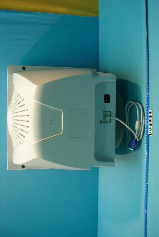
External Photos
(Photo 1) FCC ID: PIM797B (Photo 2) FCC ID: PIM797B 1
ID Label/Location Info
• This device complies with part 15 of the FCC Rules.Operation is subject to the following two conditions:(1) This device may not cause harmful interference,and (2) This device must accept any interferencereceived, including interference that may causeundesired operation. • Laite on liitettävä suojakosketinpistrasiaan, jos seon liitetty laajaan johdinverkkoon. Apparatet mä kun tilkoples jordet stikkontakt. Apparaten skall anslutas till jordat uttag när denansluts till ett nätverk. • Die erzeugten Röntgenstrahlen Werden durch dieeigensichere Kathodenstrahlröhre ausreichendabgeschirmt. Nach RöV vom 08.01.1987 Anlage III.Anodenspannung: max 27.5KV • Complies with Canadian ICES-003 class B.Conforme a la NMB-003 class B. • Complies with DHHS radiation performancestandards, 21 CFR subchapter J. NESO Technology Inc . 12F, No. 866, Chung Cheng Rd., Chung Ho City, Taipei County, Taiwan Color Monitor FCC ID: PIM797B Model : FD797P Power : 100-240V 50/60Hz 1.8A MADE IN CHINA I.T.E. E217904 714XXXX601 FS
ID Label/Location Info
(Fig. 1) FCC ID: PIM797B FCC LABEL LOCATION The label will be permanently affixed at a conspicuous location on the device. Label
Internal Photos
(Photo 3) FCC ID: PIM797B (Photo 4) FCC ID: PIM797B (Photo 5) FCC ID: PIM797B 2 (Photo 6) FCC ID: PIM797B 2 (Photo 7) FCC ID: PIM797B 1 3 4 5 6 7 (Photo 8) FCC ID: PIM797B 8 (Photo 9) FCC ID: PIM797B
Internal Photos
(Photo 10) FCC ID: PIM797B (Photo 11) FCC ID: PIM797B 9 9 9 (Photo 12) FCC ID: PIM797B (Photo 13) FCC ID: PIM797B (Photo 14) FCC ID: PIM797B (Photo 15) FCC ID: PIM797B (Photo 16) FCC ID: PIM797B (Photo 17) FCC ID: PIM797B
Test Report
FCC ID: PIM797B Report No.: F900628A051Issued: July 7, 2001 FCC TEST REPORT REPORT NO.: F900628A05 MODEL NO.: FD797P RECEIVED: June 28, 2001 TESTED: June 29 ~ 30, 2001 APPLICANT:NESO Technology Inc. ADDRESS:12F, No. 866, Chung Cheng Rd., Chung Ho City, Taipei County, Taiwan, R.O.C. ISSUED BY:Advance Data Technology Corporation LAB LOCATION:47 14th Lin, Chiapau Tsun, Linko, Taipei, Taiwan, R.O.C. This test report consists of 18 pages in total. It may be duplicated completely for legal use with the approval of the applicant. It should not be reproduced except in full, without the written approval of our laboratory. The client should not use it to claim product endorsement by CNLA, NVLAP or any government agencies. The test results in the report only apply to the tested sample. 0528 Lab Code: 200102-0 FCC ID: PIM797B Report No.: F900628A052Issued: July 7, 2001 Table of Contents 1CERTIFICATION............................................................................................. 3 2SUMMARY OF TEST RESULTS..................................................................... 4 3GENERAL INFORMATION ............................................................................. 5 3.1GENERAL DESCRIPTION OF EUT ............................................................... 5 3.2DESCRIPTION OF TEST MODES ................................................................. 5 3.3DESCRIPTION OF SUPPORT UNITS............................................................ 6 4EMISSION TEST ............................................................................................ 7 4.1CONDUCTED EMISSION MEASUREMENT .................................................. 7 4.1.1 LIMITS OF CONDUCTED EMISSION MEASUREMENT ............................... 7 4.1.2 TEST INSTRUMENTS .................................................................................... 7 4.1.3 TEST PROCEDURE ....................................................................................... 8 4.1.4 DEVIATION FROM TEST STANDARD ........................................................... 8 4.1.5 TEST SETUP .................................................................................................. 8 4.1.6 EUT OPERATING CONDITIONS.................................................................... 9 4.1.7 TEST RESULTS............................................................................................ 10 4.2RADIATED EMISSION MEASUREMENT ..................................................... 12 4.2.1 LIMITS OF RADIATED EMISSION MEASUREMENT .................................. 12 4.2.2 TEST INSTRUMENTS .................................................................................. 13 4.2.3 TEST PROCEDURE ..................................................................................... 13 4.2.4 DEVIATION FROM TEST STANDARD ......................................................... 14 4.2.5 TEST SETUP ................................................................................................ 14 4.2.6 EUT OPERATING CONDITIONS.................................................................. 14 4.2.7 TEST RESULTS............................................................................................ 15 5PHOTOGRAPHS OF THE TEST CONFIGURATION ................................... 16 6APPENDIX - INFORMATION ON THE TESTING LABORATORIES............. 18 FCC ID: PIM797B Report No.: F900628A053Issued: July 7, 2001 1 CERTIFICATION PRODUCT:COLOR MONITOR BRAND NAME:NESO MODEL NO:FD797P TEST ITEM:ENGINEERING SAMPLE APPLICANT:NESO Technology Inc. STANDARDS:FCC Part 15, Subpart B, Class B CISPR 22: 1997, Class B ANSI C63.4-1992 We, Advance Data Technology Corporation, hereby certify that one sample of the designation has been tested in our facility on June 29 ~ 30, 2001. The test record, data evaluation and Equipment Under Test (EUT) configurations represented herein are true and accurate accounts of the measurements of the sample's EMC characteristics under the conditions herein specified. FCC ID: PIM797B Report No.: F900628A054Issued: July 7, 2001 2 SUMMARY OF TEST RESULTS The EUT has been tested according to the following specifications: StandardTest TypeResultRemarks Conducted TestPASS Meets Class B Limit Minimum passing margin is –10.15 dB at 0.280 MHz FCC Part 15, Subpart B, CISPR 22: 1997, Class B Radiated TestPASS Meets Class B Limit Minimum passing margin is –2.30 dB at 202.75 MHz NOTE: For conducted emission test, the test limit used is according to FCC Part 15.107. In this part, conducted emission test for telecom port is not mentioned and therefore this item is not tested. FCC ID: PIM797B Report No.: F900628A055Issued: July 7, 2001 3 GENERAL INFORMATION 3.1 GENERAL DESCRIPTION OF EUT PRODUCTCOLOR MONITOR MODEL NO.FD797P POWER SUPPLY Switching Input rating: 100-240V, 50/60Hz Power Cord: Non-shielded, 3 pin, AC (1.8m) DATA CABLEShielded (1.5m) with a ferrite core NOTE: The EUT is a 17” COLOR MONITOR with resolution up to 1600x1200. For a more detailed features description, please refer to the manufacturer's specifications or the User's Manual. 3.2 DESCRIPTION OF TEST MODES The EUT was pre-tested under the following resolution & horizontal synchronization speed mode: ♦ 1600x1200 mode (75Hz/93kHz), ♦ 1280x1024 mode (85Hz/91kHz), ♦ 640x480 mode (60Hz/31kHz) The worst emission levels were found when the EUT was tested under 1600x1200 (75Hz/93kHz) resolution. FCC ID: PIM797B Report No.: F900628A056Issued: July 7, 2001 3.3 DESCRIPTION OF SUPPORT UNITS The EUT has been tested as an independent unit together with other necessary accessories or support units. The following support units or accessories were used to form a representative test configuration during the tests. NO.PRODUCTBRANDMODEL NO.SERIAL NO.FCC ID 1PERSONAL COMPUTER NTIPI I-333TP201102FCC DoC APPROVED 2PRINTERHP2225C+3208S05355DSI6XU2225 3MODEMACEEX1414980020502IFAXDM1414 4PS/2 KEYBOARD FORWARDFDA-104GAFDKB8110123F4ZDA-104G 5PS/2 MOUSELOGITECHM-S43LZE93502451DZL211106…
Text truncated - open the document above for the full version.
Test Setup Photos
FCC ID: PIM797B Report No.: F900628A0516Issued: July 7, 2001 5 PHOTOGRAPHS OF THE TEST CONFIGURATION CONDUCTED EMISSION TEST FCC ID: PIM797P Report No.: F900628A0517Issued: July 7, 2001 RADIATED EMISSION TEST
Contact Information
Applicant
David Wang(Manager)
Test Firm
Bureau Veritas CPS (H.K.) Ltd. Taoyuan BranchRichard Chen
Technical Specifications
| # | Rule Parts | Frequency Range | Power Output |
|---|---|---|---|
| 1 | 15B | - | - |
Other Applications from NESO Technology Inc.
PIM910B
Oct 30, 2001Color Monitor
Equipment Class
JBP - Part 15 Class B Computing Device Peripheral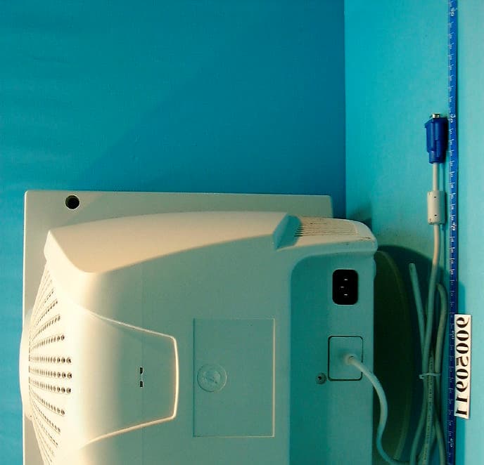
PIM786B
Jul 30, 2001Color Monitor
Equipment Class
JBP - Part 15 Class B Computing Device Peripheral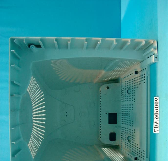
PIM570A
Jul 09, 2001Color Monitor
Equipment Class
JBP - Part 15 Class B Computing Device Peripheral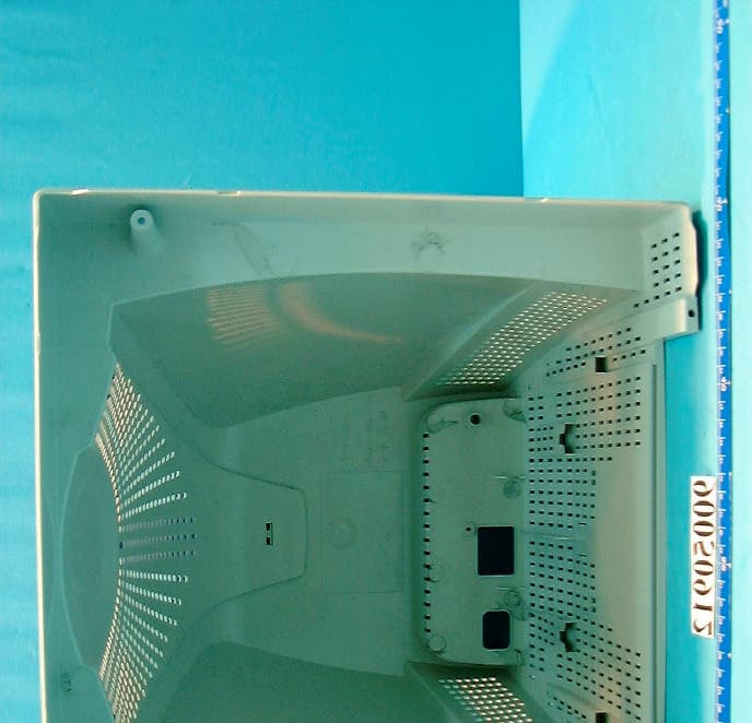
PIM772A
Jun 28, 2001Color Monitor
Equipment Class
JBP - Part 15 Class B Computing Device Peripheral